fog light AUDI Q3 2019 Owners Manual
[x] Cancel search | Manufacturer: AUDI, Model Year: 2019, Model line: Q3, Model: AUDI Q3 2019Pages: 280, PDF Size: 72.73 MB
Page 45 of 280
83A012721BA
Lights and Vision
Lights and Vision
Exterior lighting
Stare MUL Las eal
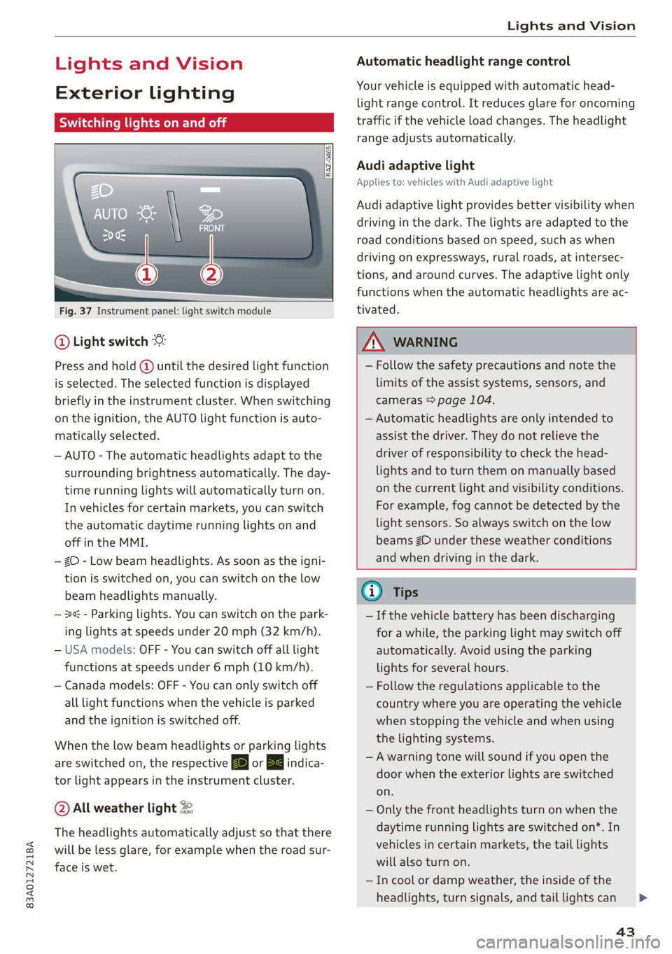
Fig. 37 Instrument panel: light switch module
@ Light switch
Press and hold @ until the desired light function
is selected. The selected function is displayed
briefly in the instrument cluster. When switching
on the ignition, the AUTO light function is auto-
matically selected.
— AUTO - The automatic headlights adapt to the
surrounding brightness automatically. The day-
time running lights will automatically turn on.
In vehicles for certain markets, you can switch
the automatic daytime running lights on and
off in the MMI.
— 20 - Low beam headlights. As soon as the igni-
tion is switched on, you can switch on the low
beam headlights manually.
— 30a - Parking lights. You can switch on the park-
ing lights at speeds under 20 mph (32 km/h).
— USA models: OFF - You can switch off all light
functions at speeds under 6 mph (10 km/h).
— Canada models: OFF - You can only switch off
all light functions when the vehicle is parked
and the ignition is switched off.
When the low beam headlights or parking lights
are switched on, the respective Ba or Ea indica-
tor light appears in the instrument cluster.
@ All weather light 2
The headlights automatically adjust so that there
will be less glare, for example when the road sur-
face is wet.
Automatic headlight range control
Your vehicle is equipped with automatic head-
light range control. It reduces glare for oncoming
traffic if the vehicle load changes. The headlight
range adjusts automatically.
Audi adaptive light
Applies to: vehicles with Audi adaptive light
Audi adaptive light provides better visibility when
driving in the dark. The lights are adapted to the
road conditions based on speed, such as when
driving on expressways, rural roads, at intersec-
tions, and around curves. The adaptive light only
functions when the automatic headlights are ac-
tivated.
Z\ WARNING
— Follow the safety precautions and note the
limits of the assist systems, sensors, and
cameras > page 104.
— Automatic headlights are only intended to
assist the driver. They do not relieve the
driver of responsibility to check the head-
lights and to turn them on manually based
on the current light and visibility conditions.
For example, fog cannot be detected by the
light sensors. So always switch on the low
beams ZO under these weather conditions
and when driving in the dark.
@) Tips
— If the vehicle battery has been discharging
for a while, the parking light may switch off
automatically. Avoid using the parking
lights for several hours.
— Follow the regulations applicable to the
country where you are operating the vehicle
when stopping the vehicle and when using
the lighting systems.
—Awarning tone will sound if you open the
door when the exterior lights are switched
on.
— Only the front headlights turn on when the
daytime running lights are switched on*. In
vehicles in certain markets, the tail lights
will also turn on.
—In cool or damp weather, the inside of the
headlights, turn signals, and tail lights can
43
Page 46 of 280
Lights and Vision
fog over due to the temperature difference
between the inside and outside. They will
clear shortly after switching them on. This
does not affect the service life of the light-
ing.
— When the parking lights are switched on
and the ignition is switched off, the 200: sym-
bol appears in the light switch module.
Turn signal and high beam lever
©
-
!
®
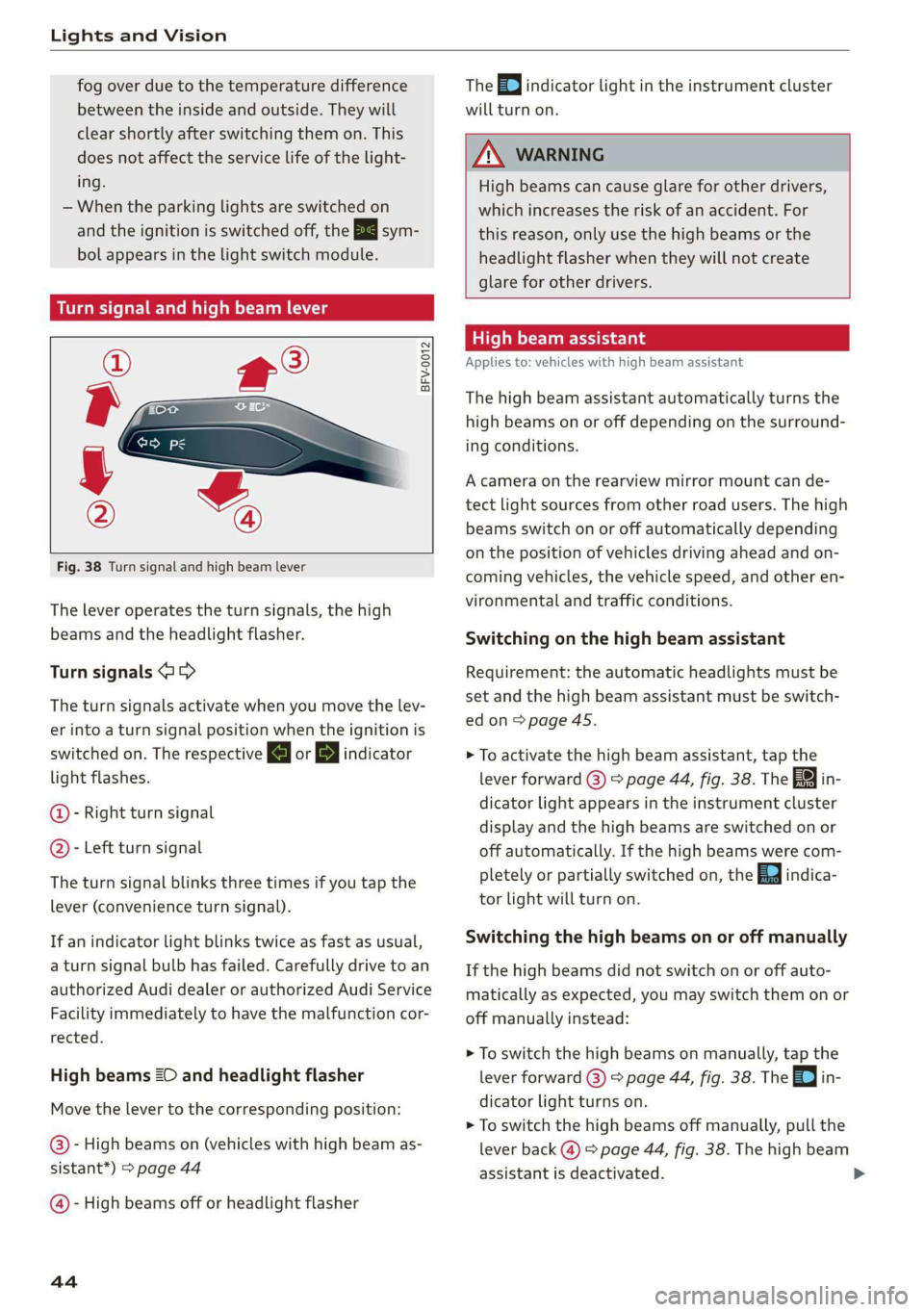
Fig. 38 Turn signal and high beam lever
The lever operates the turn signals, the high
beams and the headlight flasher.
Turn signals @ >
The turn signals activate when you move the lev-
er into a turn signal position when the ignition is
switched on. The respective a or B indicator
light flashes.
@- Right turn signal
@- Left turn signal
The turn signal blinks three times if you tap the
lever
(convenience turn signal).
If an indicator light blinks twice as fast as usual,
a turn signal bulb has failed. Carefully drive to an
authorized Audi dealer or authorized Audi Service
Facility immediately to have the malfunction cor-
rected.
High beams 2D and headlight flasher
Move the lever to the corresponding position:
@)- High beams on (vehicles with high beam as-
sistant*) > page 44
@ - High beams off or headlight flasher
44
The =0) indicator light in the instrument cluster
will turn on.
ZX WARNING
High beams can cause glare for other drivers,
which increases the risk of an accident. For
this reason, only use the high beams or the
headlight flasher when they will not create
glare for other drivers.
teh Meola
Applies to: vehicles with high beam assistant
The high beam assistant automatically turns the
high beams on or off depending on the surround-
ing conditions.
A camera on the rearview mirror mount can de-
tect light sources from other road users. The high
beams switch on or off automatically depending
on the position of vehicles driving ahead and on-
coming vehicles, the vehicle speed, and other en-
vironmental and traffic conditions.
Switching on the high beam assistant
Requirement: the automatic headlights must be
set and the high beam assistant must be switch-
edon>
page 45.
> To activate the high beam assistant, tap the
lever forward (@) > page 44, fig. 38. The 5%
dicator light appears in the instrument cluster
display and the high beams are switched on or
off automatically. If the high beams were com-
pletely or partially switched on, the Ea indica-
tor light will turn on.
in-
Switching the high beams on or off manually
If the high beams did not switch on or off auto-
matically as expected, you may switch them on or
off manually instead:
> To switch the high beams on manually, tap the
lever
forward (3) > page 44, fig. 38. The =| in-
dicator light turns on.
> To switch the high beams off manually, pull the
lever
back @) > page 44, fig. 38. The high beam
assistant is deactivated.
Page 76 of 280
Stowing and using
injury during braking maneuvers or acci-
dents.
— When transporting heavy objects, the vehi-
cle characteristics will change due to the
shift in the center of gravity, which increases
the risk of an accident. You may need to
adapt your driving style and speed to the
current conditions.
— The cargo net is only strong enough to se-
cure light objects. Heavy objects are not ade-
quately secured. Attempting to secure heavy
objects increases the risk of injury.
— Never exceed the permitted axle and load
and vehicle weight > page 264.
— Never secure a child safety seat to the tie-
downs.
— Never leave your vehicle unattended, espe-
cially if the luggage compartment lid is
open. Children could enter the luggage com-
partment and close the luggage compart-
ment lid from the inside. This creates the
risk of fatal injury, since the children would
be locked in and may not be able to escape
by themselves.
— Do not allow children to play in or on the ve-
hicle. Close and lock the luggage compart-
ment lid as well as all other doors when you
leave
the vehicle.
— Never transport passengers in the luggage
compartment. Every passenger must be cor-
rectly secured with the safety belts in the
vehicle > page 58.
—To reduce the risk of accidents, the luggage
compartment cover should never be unse-
cured
under any circumstances.
— Be careful when releasing the backrest and
folding
it forward. To reduce the risk of be-
ing pinched, pay attention and check when
folding backrests forward.
— The backrest must be securely latched so
objects cannot slide forward out of the lug-
gage compartment during sudden braking.
— The backrest must be latched securely to en-
sure that the safety belt is protecting the
center seating position.
— Always pull forward on the backrest to make
sure it is check if it is correctly locked in
place.
74
@) Note
—To reduce the risk of damage, move the rear
head restraints down > page 57 before fold-
ing the rear backrests forward.
— Objects should be removed from the rear
bench seat to protect the backrest from
damage.
— If you move the front seat back when the
rear seat backrest is folded forward, you
could damage the head restraints on the
rear seat.
— Make sure that the heating grid strips for
the rear window defogger are not damaged
by abrasive objects.
G) Tips
— The tire pressure must be adapted to the
load > page 226.
— You can purchase straps at specialty stores.
eye TE Tel-eetedaal SLA ie
\|_« ma.
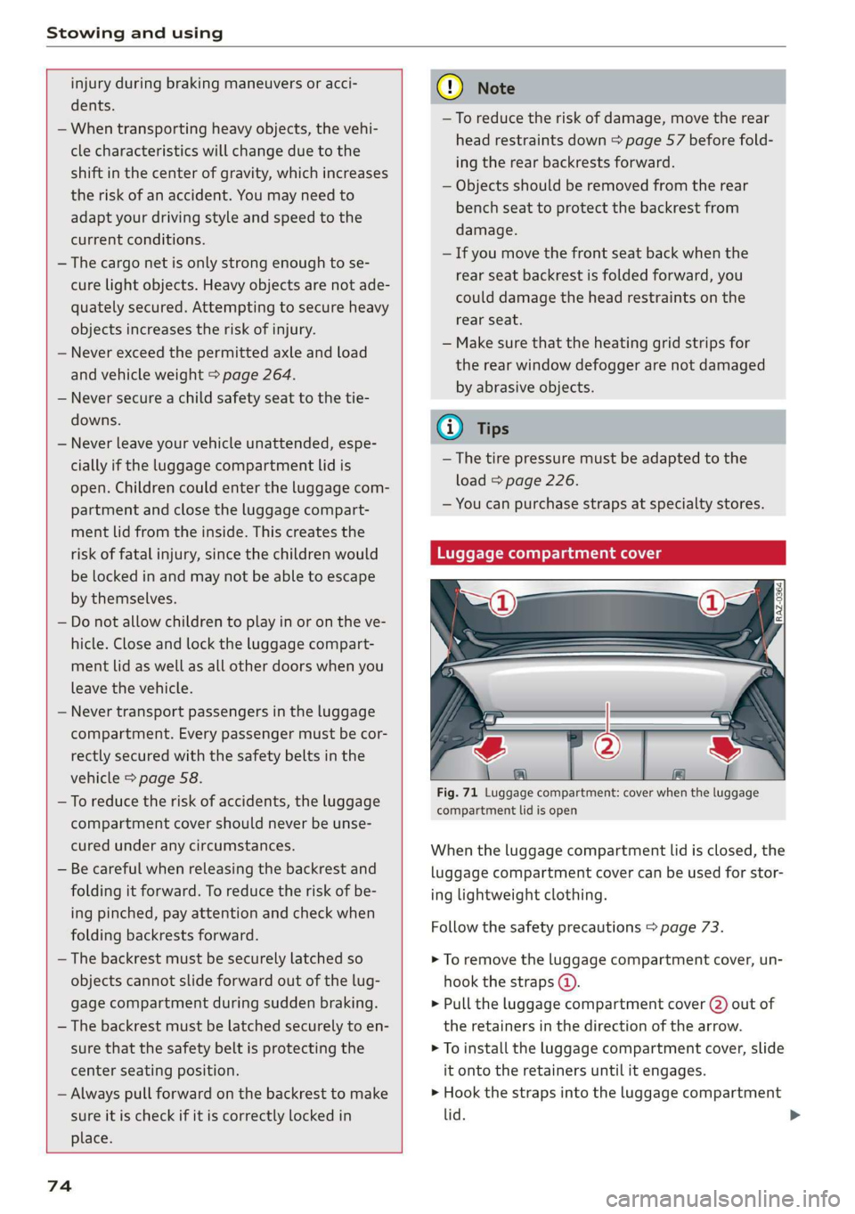
Fig. 71 Luggage compartment: cover when the luggage
compartment lid is open
When the luggage compartment lid is closed, the
luggage compartment cover can be used for stor-
ing lightweight clothing.
Follow the safety precautions > page 73.
> To remove the luggage compartment cover, un-
hook the straps @).
> Pull the luggage compartment cover (2) out of
the retainers in the direction of the arrow.
> To install the luggage compartment cover, slide
it onto the retainers until it engages.
> Hook the straps into the luggage compartment
lid.
Page 80 of 280
Warm and cold
2-zone deluxe automatic climate control
Applies to: Vehicles with 2-zone deluxe automatic climate control
B8V-0590
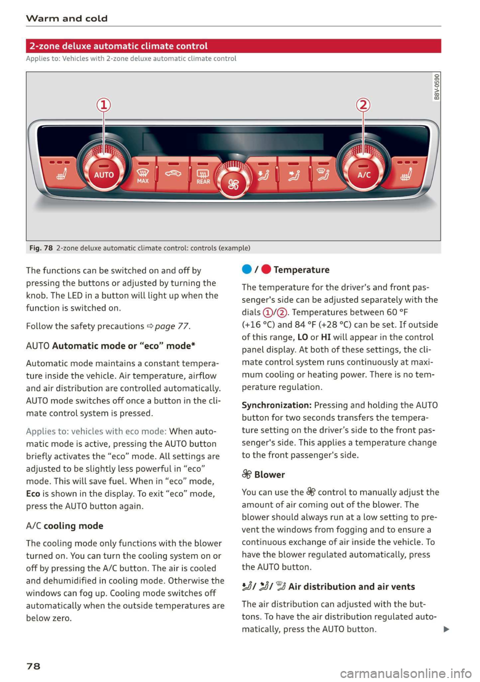
Fig. 78 2-zone deluxe automatic climate control: controls (example)
The functions can be switched on and off by
pressing the buttons or adjusted by turning the
knob. The LED in a button will light up when the
function is switched on.
Follow the safety precautions > page 77.
AUTO Automatic mode or “eco” mode*
Automatic mode maintains a constant tempera-
ture inside the vehicle. Air temperature, airflow
and air distribution are controlled automatically.
AUTO mode switches off once a button in the cli-
mate control system is pressed.
Applies to: vehicles with eco mode: When auto-
matic mode is active, pressing the AUTO button
briefly activates the “eco” mode. All settings are
adjusted to be slightly less powerful in “eco”
mode. This will save fuel. When in “eco” mode,
Eco is shown in the display. To exit “eco” mode,
press the AUTO button again.
A/C cooling mode
The cooling mode only functions with the blower
turned on. You can turn the cooling system on or
off by pressing the A/C button. The air is cooled
and dehumidified in cooling mode. Otherwise the
windows can fog up. Cooling mode switches off
automatically when the outside temperatures are
below zero.
78
@ / @ Temperature
The temperature for the driver's and front pas-
senger's side can be adjusted separately with the
dials @/@). Temperatures between 60 °F
(+16 °C) and 84 °F (+28 °C) can be set. If outside
of this range, LO or HI will appear in the control
panel display. At both of these settings, the cli-
mate control system runs continuously at maxi-
mum cooling or heating power. There is no tem-
perature regulation.
Synchronization: Pressing and holding the AUTO
button for two seconds transfers the tempera-
ture setting on the driver’s side to the front pas-
senger's side. This applies a temperature change
to the front passenger's side.
8 Blower
You can use the & control to manually adjust the
amount of air coming out of the blower. The
blower should always run at a low setting to pre-
vent the windows from fogging and to ensure a
continuous exchange of air inside the vehicle. To
have the blower regulated automatically, press
the AUTO button.
85/ 35/ @ Air distribution and air vents
The air distribution can adjusted with the but-
tons. To have the air distribution regulated auto-
matically, press the AUTO button.
Page 112 of 280
Driver assistance
Driver assistance
Cruise control system
Applies to: vehicles with cruise control system
The cruise control system assists the driver in
maintaining a constant speed above approxi-
mately 15 mph (20 km/h). The system maintains
the desired speed by braking and accelerating.
ZA WARNING
— Always pay attention to the traffic around
you when the cruise control system is in op-
eration. As the driver, you are always respon-
sible for controlling your vehicle speed and
the distance between your vehicle and other
vehicles.
— For safety reasons, cruise control should not
be used in the city, in stop-and-go traffic, on
winding roads and when road conditions are
poor (such as ice, fog, gravel, heavy rain and
hydroplaning), because this increases the
risk of an accident.
— Switch the cruise control off temporarily
when driving in turning lanes, highway exits
or in construction zones.
—To reduce the risk of an accident, you should
only resume the stored speed if it is suitable
for the current traffic conditions.
@) Note
Before driving downhill a long distance ona
steep hill, decrease your speed and select a
lower gear. This makes use of the engine brak-
ing effect and relieves the brakes.
@) Tips
The brake lights turn on when the brakes are
applied automatically.
110
Switching the system on
Applies to: vehicles with cruise control system
BFV-0220
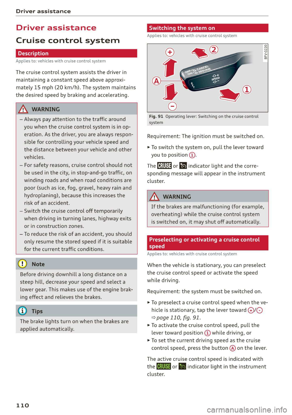
Fig. 91 Operating lever: Switching on the cruise control
system
Requirement: The ignition must be switched on.
> To switch the system on, pull the lever toward
you to position @).
The CRUISE] or [J indicator light and the corre-
sponding message will appear in the instrument
cluster.
ZA WARNING
If the brakes are malfunctioning (for example,
overheating) while the cruise control system
is switched on, it may shut off automatically.
Preselecting or activating a cruise control
speed
Applies to: vehicles with cruise control system
When the vehicle is stationary, you can preselect
the cruise control speed or activate the speed
while driving.
Requirement: the system must be switched on.
> To preselect a cruise control speed when the ve-
hicle is stationary, tap the lever toward @)/G)
= page 110, fig. 91.
> To activate the cruise control speed, pull the
lever
toward position @ while driving, or
> To set the current driving speed as the cruise
control speed, press the button @) on the lever.
The active cruise control speed is indicated with
the Gs or indicator light in the instrument
cluster.
Page 242 of 280
Care and cleaning
avoid scratches, move the scraper only in
one direction and not back and forth.
— Never remove snow or ice from door win-
dows and mirrors using warm or hot water
because this could cause cracks to form.
— To avoid damage to the rear window de-
fogger, do not apply any stickers on the
heating wires on the inside of the window.
— Decorative parts/trim
— Never use chrome care or cleaning prod-
ucts.
— Paint
—To reduce the risk of scratches, the vehicle
must be free of dirt and dust before pol-
ishing or waxing.
— To prevent paint damage, do not polish or
wax the vehicle in direct sunlight.
—To reduce the risk of paint damage, do not
polish away rust spots.
— Remove cosmetics and sunscreen immedi-
ately - these could damage the paint.
— Decorative decals
—To reduce the risk of damage, do not use
any rough powder or abrasive cleaning
products.
—To reduce the risk of damage, do not pol-
ish decorative decals that have a matte or
printed finish.
— Due to the risk of damage, do not use an
ice scraper to remove snow and ice on win-
dows with decorative decals on them.
— Displays/instrument cluster
— Make sure that the display and instrument
cluster are switched off and have cooled
down before cleaning. To switch off the
center display, select on the MMI home
screen: SETTINGS > Display & brightness
> MMI > Screen cleaning.
— Displays, the instrument cluster, and the
trim surrounding it must not be cleaned
with dry cleaning methods because they
could become scratched.
— Make sure no fluids enter the spaces be-
tween the instrument cluster and the
trim, because that could cause damage.
— Controls
240
— Make sure that no fluids enter the con-
trols, because this could cause damage.
— Safety belts
— Do not remove the safety belts to clean
them.
— Never clean safety belts or their compo-
nents chemically or with corrosive fluids
or solvents and never allow sharp objects
to come into contact with the safety belts.
This could cause damage to the belt web-
bing.
—If there is damage to the webbing, the
connections, the retractors or the buckles,
have them replaced by an authorized Audi
dealer or authorized Audi Service Facility.
—Textiles/artificial leather/Alcantara
— Never treat artificial leather/Alcantara
with leather care products, solvents, floor
polish, shoe polish, spot remove or similar
products.
— Have a specialist remove stubborn stains
to prevent damage.
— Never use steam cleaners, brushes, hard
sponges, etc. when cleaning.
— Do not turn on the seat heating* to dry
the seat.
— Objects with sharp edges, such as zippers
or rivets on clothing or belts, can cause
damage to the surface.
— Open hook and loop fasteners, for exam-
ple on clothing, can damage seat covers.
Make sure hook and loop fasteners are
closed.
— Natural leather
— Never treat leather with solvents, floor
polish, shoe polish, spot remover or simi-
lar products.
— Objects with sharp edges, such as zippers
or rivets on clothing or belts, can cause
damage to the surface.
— Never use steam cleaners, brushes, hard
sponges, etc. when cleaning.
— Do not turn on the seat heating* to dry
the seat.
—To help prevent the leather from fading,
do not leave the vehicle in direct sunlight >
Page 249 of 280
83A012721BA
Emergency assistance
Starting the engine
Both jump start cables must be connected in the
correct order.
S
g = & oO
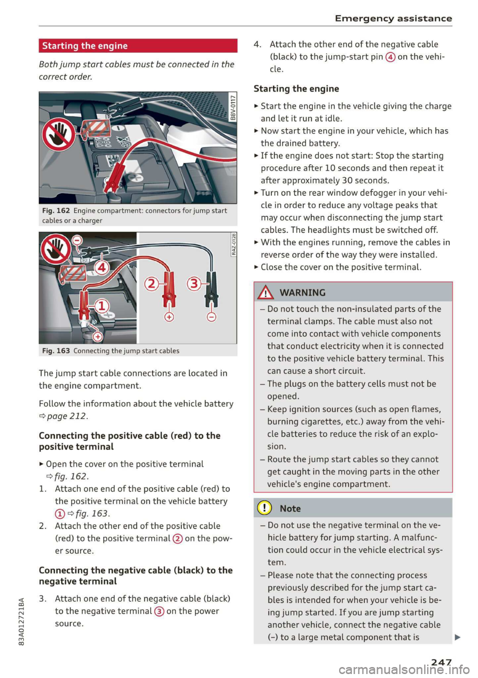
Fig. 162 Engine compartment: connectors for jump start
cables or a charger
RAZ-0128
Fig. 163 Connecting the jump start cables
The jump start cable connections are located in
the engine compartment.
Follow the information about the vehicle battery
=> page 212.
Connecting the positive cable (red) to the
positive terminal
> Open the cover on the positive terminal
> fig. 162.
1. Attach one end of the positive cable (red) to
the positive terminal on the vehicle battery
@ ° fig. 163.
2. Attach the other end of the positive cable
(red) to the positive terminal @ on the pow-
er source.
Connecting the negative cable (black) to the
negative terminal
3. Attach one end of the negative cable (black)
to the negative terminal @) on the power
source.
4. Attach the other end of the negative cable
(black) to the jump-start pin @ on the vehi-
cle.
Starting the engine
> Start the engine in the vehicle giving the charge
and let it run at idle.
> Now start the engine in your vehicle, which has
the
drained battery.
> If the engine does not start: Stop the starting
procedure after 10 seconds and then repeat it
after approximately 30 seconds.
> Turn on the rear window defogger in your vehi-
cle in order to reduce any voltage peaks that
may occur when disconnecting the jump start
cables. The headlights must be switched off.
> With the engines running, remove the cables in
reverse order of the way they were installed.
> Close the cover on the positive terminal.
ZA WARNING
— Do not touch the non-insulated parts of the
terminal clamps. The cable must also not
come into contact with vehicle components
that conduct electricity when it is connected
to the positive vehicle battery terminal. This
can cause a short circuit.
— The plugs on the battery cells must not be
opened.
— Keep ignition sources (such as open flames,
burning cigarettes, etc.) away from the vehi-
cle batteries to reduce the risk of an explo-
sion.
— Route the jump start cables so they cannot
get caught in the moving parts in the other
vehicle's engine compartment.
q@ Note
— Do not use the negative terminal on the ve-
hicle battery for jump starting. A malfunc-
tion could occur in the vehicle electrical sys-
tem.
— Please note that the connecting process
previously described for the jump start ca-
bles is intended for when your vehicle is be-
ing jump started. If you are jump starting
another vehicle, connect the negative cable
(-) to a large metal component that is
247
Page 255 of 280
83A012721BA
Fuses and bulbs
No. | Equipment No. | Equipment
7 Radio receiver, parking heater, climate Right rear window regulator motor, front
control system controls 39 | passenger side door control module, right
Headlight range control, interior monitor- rear door control module
ing, ambient lighting, light switch, roof 40 | Sockets
8 | module, emergency call system, parking 41 |Passenger's side safety belt tensioner
brake, diagnostic connector, light/raih'sen- 42 |Vehicle electrical system control module
sor
= - 43 |Amplifier
9 |Steering column electronics
- 44 | All-wheel drive control module (quattro)
10 | Display
- - 4S | Driver's side seat adjustment
11 | Vehicle electrical system control module
: 47 | Rear window wiper
12 |MMI Infotainment system control module
- ; - 52 | Suspension
13 | Driver's side safety belt tensioner
- 53 | Rear window defogger
14 | Heating and A/C system blower
: 54 | Left trailer hitch light
15 | Steering column lock
55 | Trailer hitch
16 | Cell phone booster
56 | Right trailer hitch light
17
|Instrument cluster
- - 57 | Trailer hitch socket
18 | Rearview camera, peripheral cameras
19 | Vehicle opening/start (NFC) Bulbs
20 | Instrument cluster
21 | Steering column electronics BETS Ae ha tele
23 | Panoramic glass roof For your safety, we recommend that you have
24 | Vehicle electrical system control module your authorized Audi dealer replace any bulbs for
Driver side door control module, left rear YOU
25 | window regulator motor, left rear door It is becoming increasingly more and more diffi-
control module cult to replace vehicle light bulbs since in many
26 | Vehicle electrical system control module cases, other parts of the car must first be re-
27 | Vehicle electrical system control module meved before youre able to get to the bulb:
HooFmodule,vehieleeleckrical system This applies especially to the light bulbs in the
29 front of your car which you can only reach
control module :
through the engine compartment.
30 | Auxiliary battery control module
: Sheet metal and bulb holders can have sharp
31 | Luggage compartment lid .
: - - - - edges that can cause serious cuts, parts must be
ey) Rarking system, side assist, adaptive cruise correctly taken apart and then properly put back
assist, Cameta together to help prevent breakage of parts and
Passenger occupant detection system, long term damage from water that can enter
33 | front seat ventilation, headliner interior housings that have not been properly resealed.
light
; ingbrak For your safety, we recommend that you have
34 aa io tll Deeg renee your authorized Audi dealer replace any bulbs for
reverseilights you, since your dealer has the proper tools, the
A/C system components, diagnostic con- correct bulbs and the expertise.
35 |nector, instrument panel control, rearview
mirror
LED headlights*
253
Page 274 of 280

Index
Parking aids
Adjusting ..............0 cece eee eee 138
ParkeaSsist': « weave x sequen § 3 aameG ¢ & ae & 136
Parking and maneuvering.............-. 127
Parking brake
refer to Electromechanical parking brake.. 90
Parking lightSizx « = sax « y oss = ¢ sees 2 e eee 43
Parking lock
Manually releasing................004. 85
also refer to Gears... 1.6... cee eee ee eee 82
Parking systems
Parking system plus...............04. 127
Pass-through.............-0 eee eee eee 75
Paths... . 2... cece eee eee eee 17
Pause: (Media’files):. « «cies ov scsi 6 waves oo 185
PedalSiscis saien « x waren w ¥ eae 6 ¥ mae oo ee 84
Perchlorates + mcs + 2 mews & pase 2 s wee oe oe 258
Peripheral: cameras ses ss sua se come sg cos 129
Personal route assistance. ...........00. 167
Phone
Answering/ending acall............... 146
Connecting acellphone............... 140
Connecting a second mobile device...... 141
Disconnecting a mobile device.......... 141
SEEMS cxesise o exaasan w © means i 7 seeue 5 santas 150
Phonebook
refer to ContactS............. eee eae 144
Playback (media). « + scarce» s snesnin «sneer «0 « 185
Pointiofiintenests. + vicve x x susie x 2 euswere a ones 162
Point of interest search. .......... 000005 162
also refer to Point of interest........... 162
Polishing. .... 0.0... cece eee eee eee 238
POWerSOUNCESE: 5 6 sees as cowie 8 acm & v 72,184
Power WINdOWS « sieen . ¢ ewva s 6 eae we ews a a 38
Malfunction..............00000 0a ee 38, 39
Power windows malfunction.............. 38
pre sense
refer to Audi presense.............0.. 121
Presentation mode..............2--005 174
PLOSCES eres so smnews «a ems 9 sete oe tere @ 5 177
Presets list
refer to Presets... 0.0.0... cece eee eee 177:
Pressure
Tire pressure monitoring system........ 234
TGS: 2 cccane oo ome 2 o cae ¢ o cen Yo oR 226
Progressive steering................20055 97.
272
PROLCCUINGiices oo snesies w ot ceawis w euseees we ere 238
Pyrotechnic elements............0.0e ee 258
Q
QUACEOS + wae a s wanes a xe ee & 2 HOHE 5 £ ROTOR 6 98
Selective wheel torque control........... 99
R
RAGIOS x 5 cranes % 1 cusents © 5 sesuens 6 @ exsoams oo 175, 177:
Radio text.................0.000 00 179
Station MSt sewn: + x seme + x popes F x sRWOS Fo EE 175
Radio communications equipment........ 260
Radio equipment................--004- 260
Radio Standards Specification (RSS) ....... 261
Rain/light sensor
Headlights! ween = sases 2 3 neon § x Sou 5 ae 43
Intermittent mode (windshield wipers).... 49
Random
refer to Shuffle...............000200. 187
Range (fuelslevel)isc sx seni x sree oo aneweie a a as 14
Reading lights. <= see. 2 scum 2 2 mewn o ¥ eves 46
Rear cross-traffic‘assist - a ss caw ss oes 133
Rear lid
refer to Luggage compartment lid........ 35
RearsSeatsios 2 wens <2 were ss meme oo acne 9 6 we 55
Rearishelt': ses ¢ 2 cewe so ewe 2 2 gewe ¢ none 74
Rearview camera‘: = : asec = : sees ev owen ees 129
Rear window defogger............-.0000- 79
Reception range.............-.0-.0000- 75
Recirculation mode..............0e0 eee 79
RECUPCRAEION acosece oo suexem 4 suseene oe seem « one 15
Refi ling is oc ccs 2 x unmsen 0 mci a ema 6 200
Remote control
Garage door opener...........-.000000- 40
Remote control key............---00005 32
Remote control key 32
Convenience opening and closing......... 39
Key replacement...............-0000-- 32
LED... eee 34
Replacing the battery.................. 34
SyMehnomizationticns « « ssinem « o enero « os enewoce » oe 34
Unlocking and locking............-..005 33
also refer to Vehicle key................ 32
Removing the caps (wheel bolts)......... 242
Repairs. ...... 2.0.0... eee ee eee eee 258