radio AUDI Q5 2014 Owner's Guide
[x] Cancel search | Manufacturer: AUDI, Model Year: 2014, Model line: Q5, Model: AUDI Q5 2014Pages: 316, PDF Size: 78.41 MB
Page 250 of 316
248 Tire s and whee ls
- Never mount used tires on yo ur vehicle if
you are not sure of their "previous histo
ry." Old used tires may have been dam
aged even though the damage cannot be
seen that can lead to sudden tire failure
and loss of vehicle control.
- If you notice unusual vibration or if the
vehicle pulls to one side when driving, al
ways stop as soon as it is safe to do so and check the wheels and tires for dam
age.
(D Note
Please note that summer and winter tires
are designed for the cond itions that are
Glossary of tire and loading terminology
Acces sory weight
means the comb ined we ight (in excess of
those standard items which may be rep laced)
of au toma tic tra nsmission, power steer ing,
power brakes, power windows, power seats,
radio, and heater, to the extent that these
items are availab le as factory -installed equip
ment (whether installed or not) .
Aspect ratio
means the ratio of the he ight to the w idth of
the tire in percent . Numbers of 55 or lower in
dicate a low sidewall for improved steering re
sponse and better overall handling on dry pavement .
Bead
means the part of the ti re that is made of
steel wires, wrapped or reinforced by ply cords
and that is shaped to fit the rim.
Bead s eparation
means a b reakdown of the bond between
components in the bead.
Cord
means the strands forming the plies in the
tire . typica
l in those seasons. Audi recommends
using winter tires during the winter
months. Low temperatures signif icant ly
decrease the e lasticity of summer tires,
which affects tract ion and brak ing ability.
If summer tires are used in very cold tem peratures, cracks ca n form on the tread
bars, resulting in permanent tire damage
that can cause loud driving no ise and un
balanced t ires. Audi is not responsible for
th is type of damage .
Cold tire inflation pre ssure
means the t ire p ressure recommended by the
vehicle manufacturer fo r a tire of a des ignated
s ize that has not bee n driven for more than a
coup le of miles (k ilometers) at low speeds in
the three hour period before the tire pressure
is measured or adjusted.
Curb weight
means the we ight of a motor ve hicle w ith
standard equipment including the max imum
capacity of fuel, oil, and coolant, air condi
tioning and additional weight of optiona l
equipment.
Extra load tire
means a t ire design to operate at higher loads
and at h igher inflation pressures than the cor
responding standard tire . Extra load tires may
be identified as "XL", "x l" , "EXTRA LOAD", or
"RF" on the sidewall.
Gross A xle Weight Rating ("GAWR ")
means the lo ad -carry ing capacity of a s ingle
axle system , measured at the tire-ground in
terfaces.
Gr oss Vehicle Weight Rating ("GVWR ")
means the maximum total loaded we ight of
t h e vehi cle. .,.
Page 268 of 316
266 Tire s and wheels
When the malfunction indicator is illuminat
ed, the system may not be able to detect or
signal low t ire pressure as intended. TPMS
malfunctions may occur for a variety of rea
sons, including the installation of replace
ment or alternate tires or wheels on the vehi
cle that prevent the TPMS from funct ioning
properly . Always check the TPMS malfunct ion
tellta le after replacing one or more t ires or
wheels on your veh icle to ensure that the re
p lacement or a lternate tires and wheels allow
the TPMS to continue to function properly.
Tire pressure indicator appears
Applies to vehicles: with tire pressure monitoring system
The tire pressure indicator in the instrument
cluster informs you if the tire pressure is too
low or if there is a system malfunction.
N
I
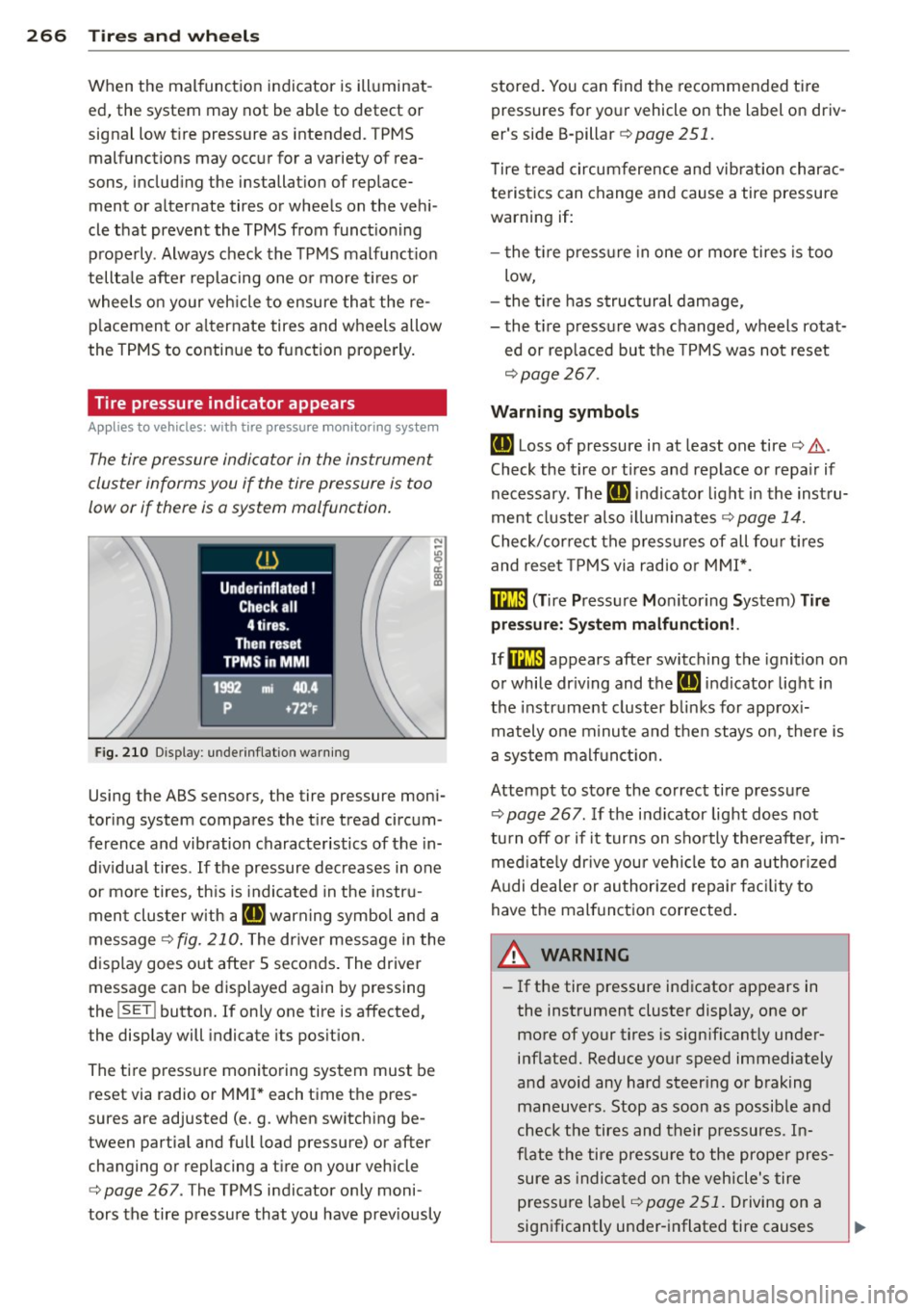
Fig. 210 Display: underinflation warning
Using the ABS sensors, the tire pressure moni
toring system compares the tire tread circum
ference and vibration characteristics of the in
dividual tires. If the pressure decreases in one
or more tires, th is is indicated in the instru
ment cluster w ith a
IE warning symbol and a
message
¢fig . 210. The dr iver message in the
display goes out after 5 seconds. The driver
message can be displayed again by pressing
the
! SET ! button. If on ly one tire is affected,
the display will indicate its position.
The tire pressure monitoring system must be
reset via radio or MMI * each time the pres
sures are adjusted (e. g . when switching be
tween partia l and full load pressure) or after
changing or replacing a tire on your vehicle
¢
page 267. The TPMS indicator only moni
tors the tire pressure that you have prev iously stored
. You can find the recommended tire
pressures for your vehicle on the label on driv
er's side B-pillar ¢
page 251.
Tire tread circumference and vibration charac
teristics can change and cause a tire pressure
warning if:
- the tir e pressure in one or more tires is too
low,
- the tir e has structural damage,
- the tir e pressure was changed, wheels rotat-
ed or replaced but the TPMS was not reset
¢page 267.
Warning symbols
IE Loss of pressure in at least one tire¢ .&..
Check the tire or tires and replace or repa ir if
necessary. The
IE indicato r light in the inst ru
ment cluster als o illuminates
¢ page 14.
Check/correct the pressures of all four tires
and reset TPMS via radio or MMI*.
ffim (T ire Pressure Mon itor ing System) Tire
pressure: System malfunction!.
If@m appears after switching the ignition on
or while dr iving and the
IE indicator light in
the instrume nt cluster blink s for app rox i
mately one minute and then stays on, there is
a system malfunction.
Attempt to store the correct tire pressure
¢
page 267 . If the indicator light does not
tu rn
off or if it turns on shortly thereafter, im
mediately drive you r vehicle to an authorized
A udi dealer or authorized repair facility to
have the malfunction corrected.
A WARNING
=
- If the tire pressure indicator appears in
the instrument cluster display, one or
more of your tires is sign ificant ly under
inflated. Reduce your speed immediately
and avoid any hard steer ing or braking
maneuvers. Stop as soon as possible and
check the tires and their pressures. In
flate the tire pressure to the proper pres
sure as ind icated on the vehicle's tire
p ressu re lab el¢
page 251. Driving on a
significantly under-inflated tire causes
Page 269 of 316
the tire to overheat and can lead to tire
failure. Under-inflation also is likely to
impair the vehicle's handling and stop
ping ability .
- The driver is responsible for maintaining
the correct tire pressures. You must
check the tire pressures regularly.
- Under certain conditions (such as a spor
ty driving style, winter conditions or un paved roads), the pressure monitor indi
cator may be delayed.
-Ask your authorized Audi dealer if run flat tires may be used on your vehicle .
Your vehicle registration becomes invalid if you use these tires when not permit
ted. Damage to your vehicle or accidents
could also result.
@ Tips
- The tire pressure monitoring system
stops working when there is an ESC/ABS
malfunction.
- Using snow chains may result in a system
malfunction.
- The tire pressure monitoring system on
your Audi was developed using tires with the "AO" or "RO" identification on the
tire sidewall¢
page 258. We recom
mend using these tires.
Reset tire pressure monitoring system
Applies to vehicles: with tire pressure monitoring system
If the tire pressure is adjusted, wheels are ro
tated or changed, the TPMS must be reset via
radio or MMI* .
.,. Before resetting the TPMS, the current pres
sures of all four tires must correspond to
the specified values. Adjust the tire pressure and reset the pressure in the tire pressure
monitoring system according to the load
you are carrying
¢ page 251 .
.. Turn on the ignition .
.,. Select :
I CARI function button > Tire pressure
monitoring
> Store now . Or
.,. Select: I CARI function button > Car systems*
control button > Servicing & checks > Tire
pressure monitoring
> Store tire pressures.
Tires and wheels 267
(D Tips
Do not store the tire pressure if there are
snow chains on the tire.
•
•
Page 283 of 316
No. Consumer
8
Gateway (Databus d iagnostic in-
terface)
9 Supplementary heater
Fuse p anel @ (b rown )
N o. Con sumer
1 CD /DVD player
2 Wi-Fi
3 MMI/Radio
4 Instrument cluster
5 Gateway
(instrument cluster
cont rol module)
6 Ignition lock
7 Light switch
8 Climate control system blower
9 Steering column lock
10 Climate contro l system
11 T
erminal 30 diagnostic connec-
tor
12 Steering column switch module
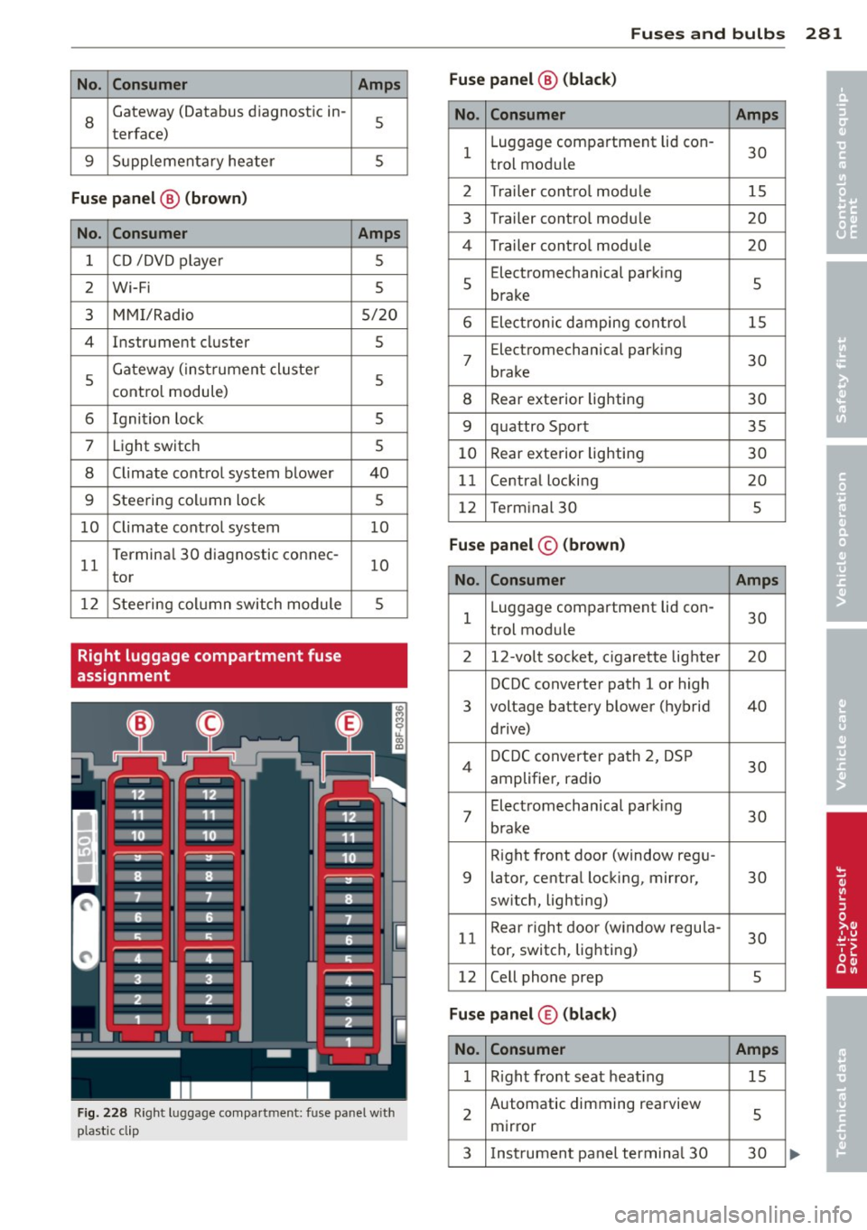
Right luggage compartment fuse
assignment Amps
5
5
Amps
5
5
5/20
5
5
5 5
40
5
10
1 0
5
Fig. 228 Right luggage compa rtment: fuse panel w ith
ptastic cl ip
Fu ses and bulb s 281
Fus e panel@ (bla ck)
•
N o. Consumer Amps •
1 Luggage
compartment lid con-
30
trol module
2 Trailer contro l modu le 15
3 Trailer contro
l modu le
20
4 Trailer cont ro l modu le 20
5 Electromechanical
parking
5
brake
6 Electronic damping contro l 15
7
Electromechanical parking
30
brake
8 Rear exterior lighting
30
9 quattro Sport
35
10 Rear
exterior lighting
30
1 1 Centra l locking 20
12 Terminal 30 5
Fuse pan el© (brown )
No . Consumer Amps
1 Luggage compartment lid con-
30
trol module
2 12-vo lt socket, c igarette lighte r 20
DCDC converter path 1 or high
3 voltage
battery blower (hybrid 40
drive)
4 D
CDC converter path 2, DSP
30
amplifier, radio
7
Electromechan ical parking
30
brake
Right front door (window regu-
9 lator, central locking, mirror,
30
switch, lighting)
11 Rear
right door (window regu la-
30
tor, switch, lighting)
12 Cell phone prep
5
Fuse panel ® (bla ck )
No. Consumer Amps
1 Right front seat heat ing 15
2 Automatic dimming
rearview
5
mirror
3 Instrument panel termina l 30 30
Page 284 of 316
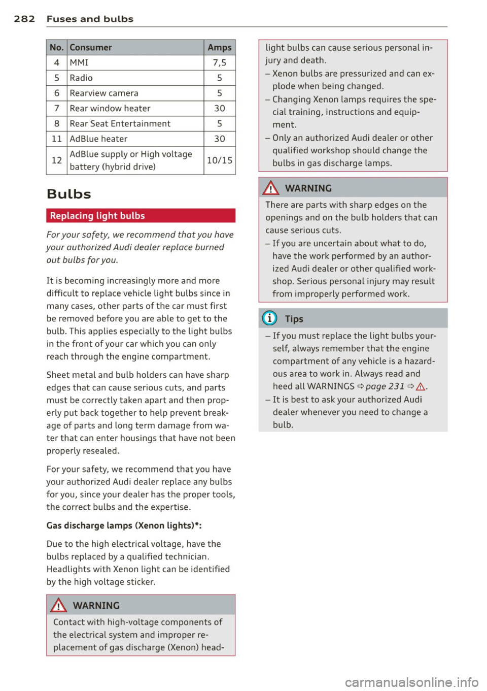
282 Fuses and bulb s
No. Consumer Amps
4 MMI 7,5
5
Radio 5
6 Rearview camera 5
7
Rear w indow heater 30
8 Rear Seat Enterta inment s
1 1 AdBlue hea ter 30
1 2
Ad Blue supply or High vo ltage 1 0/ 15
battery (hybrid dr ive)
Bulbs
Replacing light bulbs
F or your safety, we recommend that you have
your authorized Audi dealer replace burned
out bulbs for you.
It is becoming i ncreas ingly mo re and more
d iff icu lt to replace vehi cle lig ht bulbs s ince in
many cases, other parts of the car m ust first
be removed before yo u are ab le to get to the
bu lb. Th is app lies especia lly to the light bu lbs
in the front of your car which you can on ly
reac h throug h the engine compartment.
Sheet metal and bulb ho lde rs can have sharp
edges that can cause ser ious cuts, and parts
must be correctly taken apart and then prop·
erly put back together t o help prevent break
age of par ts a nd long term damage from wa
ter that ca n ente r hous ings that have not been
p roperly resealed.
For your safety, we recommend that you have
your author ized Audi dealer replace a ny bulbs
for you, since your dealer has the p roper tools,
the co rrect bu lbs and the expertise.
Gas d ischarge lamps (Xenon lights )*:
Due to the hig h electrical vo ltage, have the
bu lbs rep laced by a qualified technician.
Headlig hts with Xenon light can be identified
by the high voltage sticker.
A WARNING
Contact with high-voltage components of
t he electrical system and improper re
pl acement of gas dis charge (Xenon) head- light bulbs can cause ser
ious personal in·
j u ry and death.
- Xenon bulbs are pressur ized and can ex
plode when being changed.
- Changing Xenon lamps re quires the spe
cial tra ining, instructions and equip
ment.
- Only an auth orized A udi dealer or other
qualified wor kshop should change the
bu lbs in gas discharge lamps.
A WARNING
There are parts with sharp edges on the
openings and on the bulb holders that can
cause ser ious c uts.
- If you are uncertain about what to do,
have the work performed by an a uthor
ized Audi dealer or othe r qualified wo rk·
shop. Serious personal in jury may resul t
fr om imprope rly performed wo rk.
(D Tips
- If you must replace the light bulbs your ·
self, a lways remember tha t the eng ine
compar tment of any vehi cle is a hazard
ous area to work in. A lways read a nd
hee d all WARNI NGS
~page 231 ~ & .
-It is best to ask your authorized Audi
de aler whenever yo u need to c hange a
bulb .
-
Page 291 of 316
Technical Data
Vehicle identification
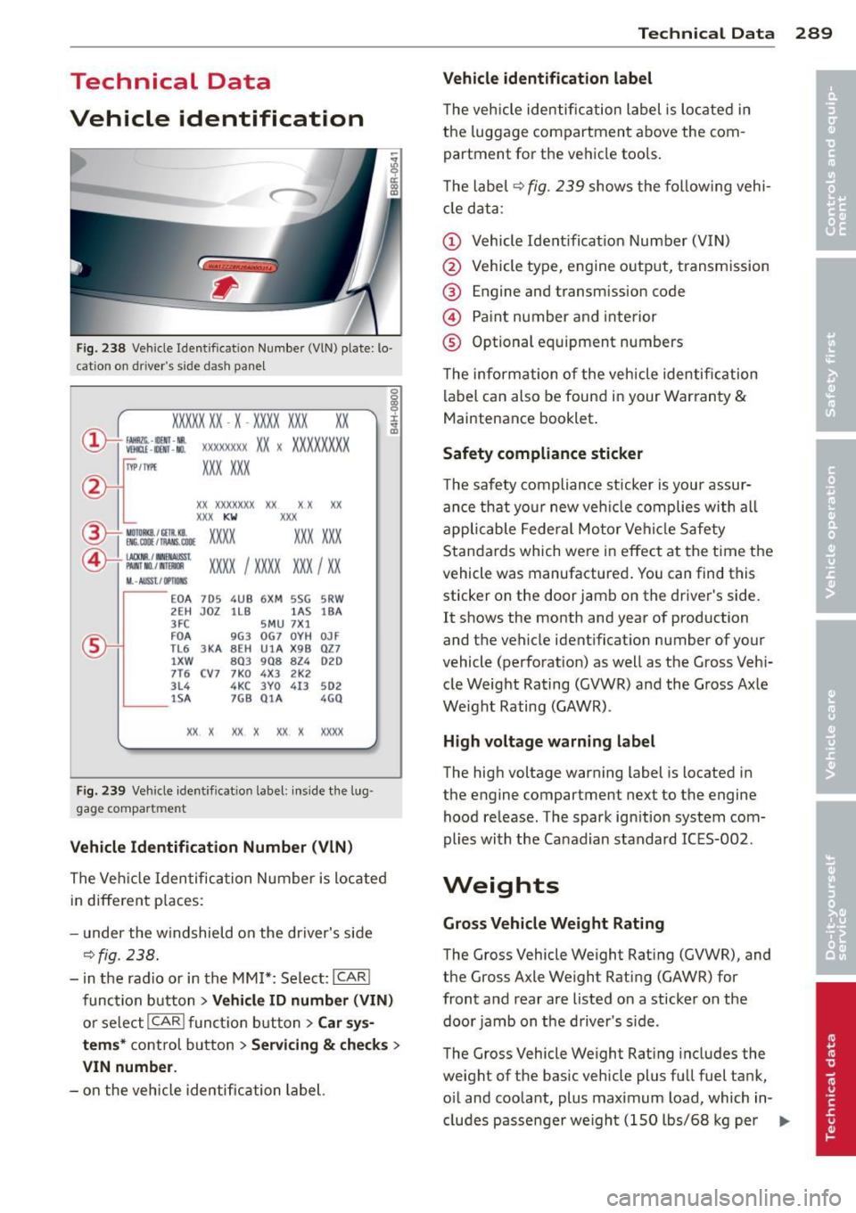
F ig. 238 Veh ide Identificat ion Numbe r (VlN) plate: lo ·
c ation on dri ver 's s ide das h pane l
XXXXX XX · X -XXXX XXX
~ fAllftlli. -llllll · NR. ~ W!ru -IIOO -NO.
xx
XXXX XXXX XX X XXXXXXXX
XXX XXX
IYP /TYPE
XX XXXXXXX XX X X XX
XXX KW XXX
®i ~W.::·f :l~~ XXXX XXX XXX
©+ ::rw= xxxx I xxxx XXX I xx
M. · AUSSt I IJ'IIDIIS
~--
EOA 7D 5 4UB 6XM SSG SRW
2E H JDZ 1LB lA S 1BA
3FC SMU 7X l
FD A 9G3 OG7 OYH OJF
TL6 3 KA 8EH UlA X98 027
lXW 803 908 824 D2D
7T6 CV7 7KO 4X3 2K2
3L4 4KC 3YO 413 502
1S A 7GB 01A 4GO
XX. X XX X XX X XXXX
Fig. 239 Vehicle identificat io n label: ins ide t he lug
ga ge compar tmen t
Vehicle Id entification Numb er (VlN )
The Veh icle Iden tifica tion Number is located
in different p laces :
- under the w indshield on the driver's side
¢fig. 238.
- i n the radio or in the MM!*: Select:
ICAR I
function button > Vehicle ID numb er (VIN )
or select I CAR I func tion button > Car sys·
tem s* control button > Servicin g & check s >
VIN numbe r.
-on the vehicle identification label.
Te chni cal Data 289
Vehicle id ent ification label
T he vehicle identification label is located in
the luggage compartment above the com
partment fo r th e ve hicle tools.
T he label¢
fig. 239 shows the fol low ing vehi
cle data :
(D Vehicle Ident ificat ion Number (VIN)
@ Vehicle type, engine o utp ut, transmission
® Engine and transmission code
© Paint number and inte rior
® Optional equipment numbers
T he information of the vehicle identification
label can also be found in your Warranty
&
Maintenance booklet .
Safety compliance sticker
T he safety compliance sticker is your assur
ance that your new veh icle complies with all
applicable Fede ra l Motor Vehi cle Safety
Standards which were in effect at the time the
vehicle was manufactured . You can find this
sticker on the door jamb on the driver 's side.
It shows the month and year of production
and the vehicle ident ificat ion number of your
vehicle (perforation) as well as the Gross Veh i
cle Weight Rating (GVWR) and the Gross Axle
Weight Rating (GAWR) .
High voltage warning label
The high voltage warning label is located in
the engine compartment next to the engine
hood release. The spark ign ition system com
plies with the Ca nadian standard ICES-002 .
Weights
Gross Vehicle Weight Rating
The Gross Vehicle Weight Rat ing (GVWR), and
the Gross Axle Weight Rati ng (GAWR) for
front and rear are listed on a sticker on the
doo r jamb on the driver's side.
The Gross Vehicle Weight Rat ing includes the
weight of the basic vehicle plus full fuel tank,
o il and coolant, plus maximum load, which in
cludes passe nger we ight (150 lbs/68 kg per
II>--
Page 298 of 316
296 Consumer Information
Technical Modifications
Our guidelines must be complied with when technical modifications are made .
Always consult an authorized Audi dealer be
fore starting work on any modifications.
This will help ensure that vehicle function,
performance and safety are not impaired
¢ &. .
Attempting to work on electronic components
and the software used with them can cause
malfunctions. Because of the way electronic
components are interconnected with each
other, such malfunctions can also have an ad
verse affect on other systems that are not di
rectly involved. This means that you risk both
a substantial reduction in the operational
safety of your vehicle and an increased wear of
ve hicle parts ¢
A:,..
Author ized Audi dealers will perform th is
wo rk in a professiona l and competent manner
or, in special cases, refer you to a professional
company that specializes in such modifica
tions .
A WARNING
Improper repairs and modifications can
change the way vehicle systems work and
cause damage to the vehicle and serious
personal injury.
-
If emergency repairs must be performed
elsewhere, have the vehicle examined by
an authorized Audi dealer as soon as possi
ble.
Declaration of
Compliance, Telecom
munications and
Electronic Systems
Radio Frequency Devices and Radiocommuni
cation Equipment User Manual Notice.
The manufacturer is not responsib le for any
radio or TV interference caused by unauthor
ized modifications to this equipment.
Devices
T he following devices each comply with FCC
Part 15.19, FCC Part 15.2 1 and RSS-Gen Iss ue
1:
- Adapt ive cru ise control*
- Conven ience key*
- Aud i side assist*
- Cell phone package*
- Electron ic immobilizer
- Homelink universal remote control*
- Remote control key
FCC Part 15.19
This device complies with part 15 of the FCC
Rules . Operation is subject to the follo wing
two conditions:
(1) This device may not cause harmful inter
ference, and
(2) this device must accept any interference
received, including interference that may
cause undesired operation.
FCC Part 15 .21
CAUTION:
Changes or modifications not expressly ap
proved by the party responsible for compli
ance could void the user's authority to operate
the equipment.
RSS-Gen Issue 1
Operation is subject to the following two con
ditions:
(1) this device may not cause inte rfe rence,
and