sensor AUDI Q5 2014 Owner's Guide
[x] Cancel search | Manufacturer: AUDI, Model Year: 2014, Model line: Q5, Model: AUDI Q5 2014Pages: 316, PDF Size: 78.41 MB
Page 181 of 316
-Always install rear-facing child safety
seats on the rear seat.
- If you must install a rearward facing
child safety seat on the front passenger
seat in exceptional circumstances and
the
PASSENGER AIR BAG OFF light does
not come on and stay on, immediately
install the rear-facing child safety seat in
a rear seating position and have the air
bag system inspected immediately by
your Audi dealer.
_& WARNING
If, in exceptional circumstances, you must
install a forward-facing child restraint on
the front passenger's seat:
- Always make sure the forward-facing
seat has been designed and certified by its manufacturer for use on a front seat
with a passenger front and side airbag.
- Always follow the manufacturer's in
structions provided with the child safety
seat or carrier.
- Always move the passenger seat into its
rearmost position in the seat's fore and
aft adjustment range, as far away from
the airbag as possible before installing
the child restraint. The backrest must be
adjusted to an upright position .
- Always make sure that the
PASSENGER
AIR BAG OFF
light comes on and stays
on all the time whenever the ignition is
switched on.
(D Tips
Always replace child restraints that were
installed in a vehicle during a crash. Dam
age to a child restraint that is not visible
could cause it to fail in another collision
situation.
Advanced front airbag system and children
Your vehicle is equipped with a front "Ad
vanced Airbag System" in compliance with United States Federal Motor Vehicle Safety
Child Safety 1 79
Standard (FMVSS) 208 as applicable at the
time your vehicle was manufactured.
The Advanced Airbag system in your vehicle
has been certified to meet the "low-risk" re
quirements for 3- and 6-year old children on
the passenger side and small adults on the driver side. The low risk deployment criteria
are intended to reduce the risk of injury
through interaction with the airbag that can
occur, for example, by being too close to the
steering wheel and instrument panel when
the airbag inflates . In addition, the system
has been certified to comply with the "sup
pression" requirements of the Safety Stand
ard, to turn off the front airbag for infants up
to 12 months who are restrained on the front
passenger seat in child restraints that are list
ed in the Standard.
Even though your vehicle is equipped with an
Advanced Airbag system, all children, espe cially those 12 years and younger, should al
ways ride in the back seat properly restrained
for their age and size. The airbag on the pas
senger side makes the front seat a potentially dangerous place for a child to ride . The front
seat is not the safest place for a child in a for
ward-facing child safety seat. It can be a very
dangerous place for an infant or a larger child
in a rearward-facing seat .
Advanced Airbags and the weight
sensing mat in the front seat
The Advanced Airbag System in your vehicle
detects the presence of an infant or child in a
child restraint on the front passenger seat us
ing the weight -sensing mat in the seat cush
ion and the sensor below the safety belt latch
on the front passenger seat that measures the
tension on the safety belt.
The weight -sensing mat measures total
weight of the child and the child safety seat
and a child blanket on the front passenger seat. The weight on the front passenger seat
is related to the design of the child restraint
and its "footprint", the size and shape of the
bottom of the child restraint as it sits on the ..,.
•
•
Page 182 of 316
180 Child Saf ety
seat. The weight of a child restraint and its
"footprint" vary for different kinds of chi ld re
straints and for the d ifferent models of the
same kind of child restraint offered by child
restra int manufacturers .
The weight ranges for the individual types, makes and mode ls of ch ild restra ints that the
NHTSA has specified in the Safety Standard
together with the we ight ranges of typical in
fants and typical 1 year-old child have been
stored in the control unit of the Advanced A ir
bag System. When a ch ild restrai nt is being
used on the front passenger seat with a typi
cal 1 yea r-old ch ild, the Advanced Airbag Sys
tem compares the we ight measured by the
weight sensing mat with the in formation stor
ed in the electronic contro l unit.
The ele ctron ic cont rol unit also registers the
tension on the front passenge r safety belt.
The tension on the safety be lt fo r the front
passenger seat will be different for an ad ult
who is properly using the safety belt as com
pared to the tension on the be lt when it is
used to attach a child restraint to the seat.
The sensor below the latch for the safety belt
for the front seat passenger measu res the
tension on the be lt . T he input from this sen
sor is then used with the we ight to "dec ide",
whe ther there is a ch ild restraint w ith a typ ica l
1 year-o ld child on the front passenger seat
and whether or not the airbag must be turned
off .
Child restraints and Advanced Airbags
Regardless of the child restraint that you use,
make sure that it has been certified to meet
United States Federal Motor Vehicle Safety
Standards a nd has been certified by its manu
facture r fo r u se w ith an airbag . Always be s ure
that t he ch ild res traint is p rope rly insta lled at
one o f th e rear seat ing pos itions . If in excep
tional c ircu mstances you must use it on the
front passenger seat, caref ully read all of the
info rmation on c hild safety and Advanced Air
bags and heed a ll of the applicable WARN
INGS. Make certain that the child restraint is
correctly recognized by the weig ht-sensing mat
inside the front passenger seat, that the
front passenger airbag is turned off and that
the a irbag stat us is a lways cor rect ly signa led
by the
PASSENGER AIR BAG OFF light.
Many types and models of child res traints
have been available over the years, new mod
els are introduced regu larly incorporating new
and improved des igns and o lder models are
taken out of product ion. Ch ild restraints are
not standard ized . Child restraints of the same
type typically have d ifferent weights and sizes
and diff erent 'footpr ints,' the s ize and shape
of the bo ttom of the ch ild restra int that sits
o n t he seat, when they a re inst alled on a vehi
cle sea t. Th ese d ifferences make i t vir tually
impossible to certify compliance with the re
quirements for advanced airbags with eac h
and every ch ild restra int that has ever been
sold in the past or will be sold over the course of the useful life of your veh icle.
For t his reason, the United States National
Highway Traffic Safety Adm inistrat ion has
published a list of spec ific type, makes and
models of child restraints that mus t be used
to certify comp liance of the Advanced Airbag
System i n your veh icle w ith the suppression
requirements of Federal Motor Vehicle Safety
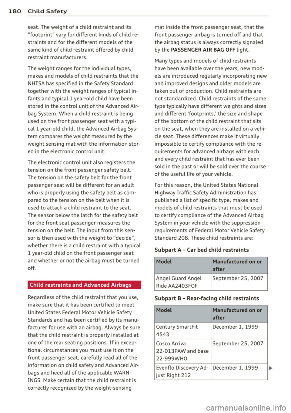
Standa rd 208. These chi ld restraints are :
Subpart A - Car bed child restraints
Model Manufactured on or
after
A ngel Guard A ngel September 25, 200 7
R ide AA 2403FOF
Subpart B - Rear-facing child restraints
Model Manufactured on or
after
Ce ntury Smart Fit Decembe r 1, 1999
4543
Cosco Arriva September 25, 2007
22-013PAW and base 22-999WHO
E venflo Discovery Ad -December 1, 1999
just Right 212
Page 205 of 316
speeds which are suited to the road con
ditions -risk of crash.
Energy management
Starting ability is optimized
Energy management controls the distribution
of electrical energy and thus optimizes the
availability of electrical energy for starting
the engine .
If a vehicle with a conventional energy system
is not driven for a long period of time , the bat
tery is discharged by idling cu rrent consumers
(e.g. immobilizer). In ce rtain c ircumstances it
can result in there being insuff icient ene rgy
avai lab le to s tart the engine .
I ntelligent energy management in your vehi
cle hand les the d ist ribution of electrical ener
gy. Starting ab ility is marked ly imp roved and
the life of the battery is extended.
Basically , energy management consists of
b atter y dia gno sis, idling curr ent manag e
m ent
and dynami c en ergy m anag emen t.
Battery diagnosis
Battery d iagnosis continuously determ ines
the state of the battery . Sensors determ ine
battery vo ltage, battery curren t and battery
temperature. This dete rm ines the current
state of charge and the power of the battery .
Idling current management
Idling current management reduces energy
consumpt ion wh ile the veh icle is stand ing .
W ith the ignition switched off, it cont ro ls the
energy s upply to the va rio us electr ical compo
nents. Data from battery diagnosis is consid
ered.
D epending on the batte ry's state of charge,
i nd ividual consumers are grad ua lly turned off
to p revent excessive discharge of the battery
and thus maintain starting capability .
Dynamic energy management
W hil e the vehicle is being driven, dynamic en
e rgy management dist ributes t he energy gen-
Int ellig ent technolog y 203
erated according to the needs of the individ u
al components. It regulates consumption, so
that more electrical energy is not being used
than is being generated and ensures an opti
mal state of charge for the battery.
(D Tips
- But even energy management cannot
negate the limits of physics. Consider
that the power and life of a battery are
limited.
- If start ing ability is t hreatened, the indi
cator light(•] appears¢
page 34 .
What you should know
The highest priority is given to maintaining
star ting capability.
The battery is severe ly taxed in short-distance
driving, in city traff ic and during the cold time
of year. Abundant elect rical energy is re
quired, but only a lit tle is generated . It is also
crit ical if the engine is not running and electri
cal components are turned on. In this in
stance ene rgy is be ing consumed but none is
being genera ted .
It is in precisely these situations that you will
not ice energy management actively regulat
ing the d istribution of ene rgy.
Vehicle stand s for an e xtended period
If you do not drive your vehicle over a period
of several days or weeks, e lectr ical compo
nents are gradually cut back or switched off.
This reduces energy consumption and ma in
ta ins start ing capability over a longer pe riod .
Some of the convenience func tions may not
opera te , such as the interior ligh ts or the
power seat adjustment. The convenience
funct ions w ill be available again when you
switch on the ignition and start the engine.
With the en gine turn ed off
If you listen to the radio, for exam ple, w ith
the engine turned off or use other MMI* func-
tions, the battery is being discharged .
11>-
•
•
Page 220 of 316
218 Vehicle care and cleaning
A WARNING
- Only wash the vehicle when the ignition
is off and follow the instructions from
the car wash operator to reduce the risk
of accidents .
- To reduce the r isk of cuts, protect your
self from sharp meta l components w hen
wash ing the unde rbody or the inside of
the whee l housings.
- After washing the vehicle, the braking ef
fect may be de layed due to mo isture on
the b rake ro to rs or i ce in the winter. The
brakes must be dried first with a few
careful brake applications.
(!;) Note
- If you wash t he vehi cle in an automatic
ca r wash, yo u m ust fold the exterior m ir
ro rs in to reduce the r is k of damage to
the mirrors. Power folding exte rior m ir
ro rs * must only be folded in and out us
i ng the power folding function.
- Compare the track of your vehicle wit h
the distance between the gui de rails of
the facility - there is a risk of damage to
the wheels and t ires.
- Compare the height and width of your
vehicle with the he ight and width of the
tunnel at the fac ility. -
To p revent paint damage, do not wash
the vehicle in di rect sunlight.
- T o reduce the ris k of damage to the sur
face, do not use insect removing spong
es, kitchen sponges or similar items.
- M atte finish painted veh icle compo
nents:
- To reduce the risk of damage to the
surface, do not use polishi ng agents or
hard wax.
- Never use car wash cycles that apply protective wax.
It can destroy the
matte fi nish effect.
- Do not place any stickers o r magnet ic
signs on v ehicle parts painted w ith
ma tte fi nish paint. The paint cou ld be
damaged when the stickers o r mag nets
a re removed .
@ For the sake of the environment
O nly wash the ve hicl e in facili ties spe cially
d esi gned for that p urpose. This will red uce
the r is k of dirty wate r contam ina ted with
o il from entering the sewer system.
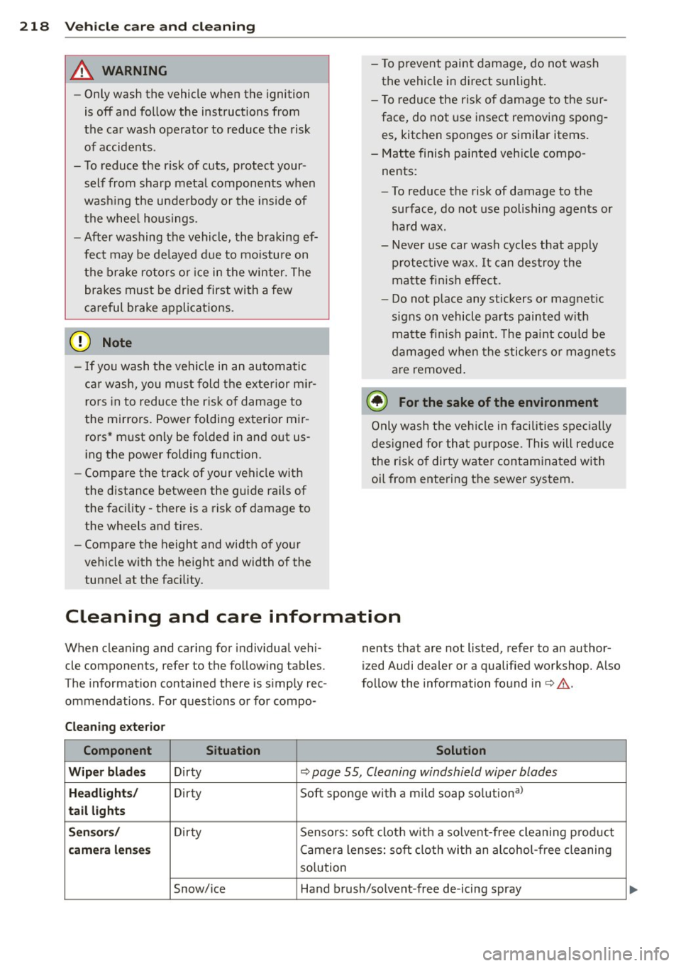
Cleaning and care information
When cleaning and caring for individua l vehi
cle components, refer to the fo llowing tab les .
The information contained there is simp ly rec
ommendat ions . For quest io ns or for compo- nents that are not listed, refer to an author
ized Audi dealer or a qualified workshop. Also
fo llow the information found in <=> & .
Cleaning exterior Component Situation Solution
Wiper blad es Dirty <=> page 55, Cleaning windshield wiper blades
Headlights/ Dirty Soft sponge with a mild soap so
lution al
tail lights
Sen sors / Dirty Sensors : soft clot h w it h a so lvent-free cleaning p roduct
camera l enses Camera lenses: soft cloth with an alcohol -free cleaning
so lution
Snow/ice Hand brush/so lvent -free de-icing spray
Page 222 of 316
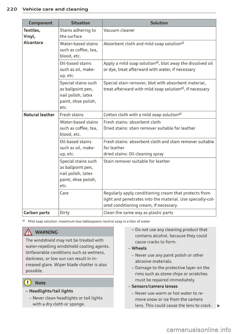
220 Vehicle care and cleaning
Component Situation Solution
T ex tile s,
Stains adhering to Vacuum cleaner
Vin yl, the surface
Alcan ta ra Water -based stains Absorbent cloth and mild soap solutiona>
such as coffee, tea,
blood, etc.
O il-based stains Apply a mild soap solutiona>, blot away the d issolved oil
such as oil, make- or dye, treat afte rward w ith water, if necessary
up, etc.
Special stains such Special stain remover, b lot with absorbent material,
as ballpoint pen, treat afterward with mild soap solutiona>, if necessary
na il polish, latex
pa int, shoe po lish,
etc.
Natu ral leather Fresh stains Cotton cloth with a mild soap solutiona>
Wate r-based stains Fresh s tains: absorbent cloth
such as coffee, tea, Dr ied stains: sta in remover sui table for leather
blood, etc.
Oi l-based stains Fresh stains: absorbent cloth and sta in remover suitable
such as oil, make- for leather
up, etc. dried stains: Oil cleaning spray
Special stains such Stain remover suitable for leather
as ballpo int pen,
na il polish, latex
pa int, shoe polish,
etc.
Care Regular
ly apply condit ion ing c ream that protec ts from
light a nd penetrates into the materia l. Use specially-col-
ored conditioning cream, if necessary.
Carbon part s Dirty Clean tlhe same way as plastic parts
a) Mi ld soap solut ion : maximum two tablespoons neut ra l soap in a lite r of wate r
& WARNING
The windshie ld may not be treated with
water -repe lling windshield coating agents .
Unfavorab le conditions such as wetness,
darkness, or low sun can result in in
creased glare. W iper blade chatter is a lso
possible .
(V Note
-Headlights /tail lights
- Never clean headlights or tail lights
w it h a dry cloth or sponge. -
Do not us e any cleaning product that
contains alcohol, because they could
cause cracks to form.
-Wheels
- Never use any paint polish or other
abrasive mater ials.
- Damage to the protective layer on the
rims such as stone chips or scratc hes
must be repa ired immediately.
- Sensor s/camera lenses
- Never use warm or hot water to re-
move snow or ice from the camera
le ns. Th is could cause th e lens to crack . ""
Page 241 of 316
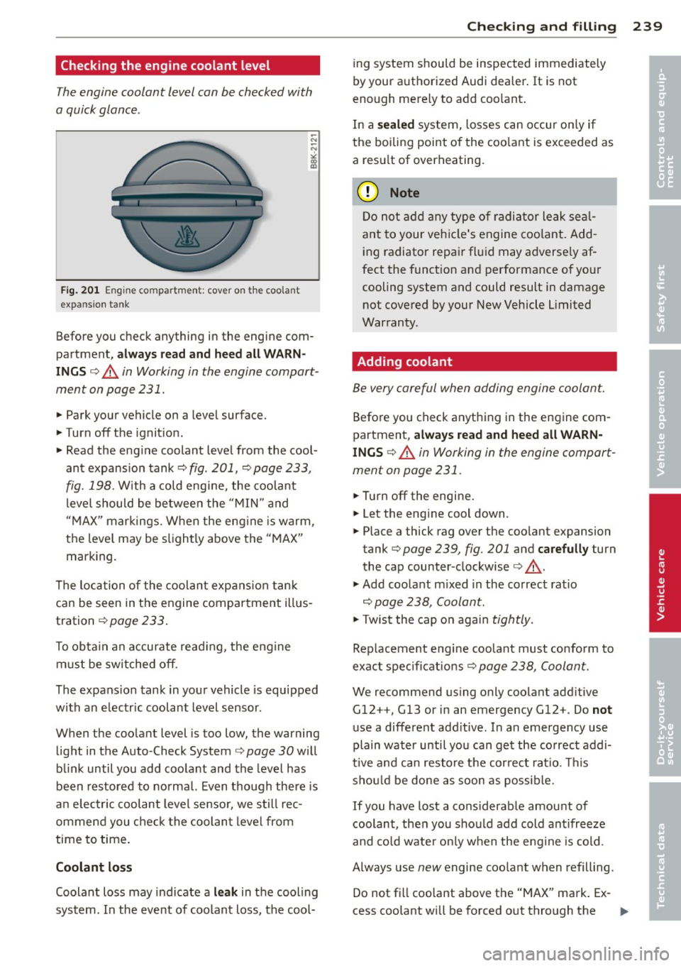
Checking the engine coolant level
The engine coolant level can be checked with
a quick glance .
Fig. 201 Eng ine co mpa rtme nt: cove r on the coola nt
exp ansion tank
Before you check anything in the engine com
partment,
a lway s re ad and he ed all WARN
INGS ¢ A in Working in the engine compart
ment on page 231 .
.,. Park your vehicle on a level surface.
.,. Turn off t he ignit ion.
.,. Read the eng ine coolant level from the cool
ant expansion tank¢ fig . 201, ¢ page 233,
fig. 198 . With a cold eng ine , the coola nt
level should be between the "M IN " and
"MAX" markings . W hen the eng ine is warm,
the leve l may be slightly above the "MAX"
marking.
The location of the coolant expans ion tank
can be seen in the engine compartment illus
tration ¢page 233.
To obtain an accurate read ing, the eng ine
must be switched off.
The expans ion tank in your vehicle is equipped
with an e lectr ic coolant level sensor .
When the coo lant level is too low, the warning
light in the Auto -Check System ¢ page 30 will
blink until you add coo lant and the level has
been restored to normal. Even though there is
a n elec tric coolant leve l sensor, we s till rec
ommend you chec k the coolant leve l from
time to time .
Coolant loss
Coolant loss may indicate a leak in the cool ing
system. In the event of coolant loss, the cool-
Checkin g and fillin g 239
ing system shou ld be inspected immediately
by your authorized Audi dealer . It is not
eno ugh merely to add coo lant .
In a
s ealed system, losses can occu r on ly if
the boiling point of the coo lant is exceeded as
a resu lt of overheating.
(D Note
Do not a dd any type o f radiator leak se al
ant to your veh icle's engine coo lant. Add
ing radiator repa ir flui d may adverse ly af
fect the funct ion and performance of yo ur
cooling system and could result in damage not covered by your New Vehicle Limited
Warranty.
Adding coolant
Be very careful when adding engine coolant.
Before you check anything in the engine com
partment,
always read and heed alt WARN
INGS ¢ A in Working in the engine compart
ment on page 231 .
.,. Turn off the engine .
.,. Let the engine cool down.
.,. Place a thick rag over the coo lant expansion
tank ¢ page 239, fig. 201 and
carefully turn
the cap counter -clockwise ¢
_& .
.,. Add coolant m ixed in the co rrect rat io
¢ page 238, Coolant.
.,. Twis t the cap o n aga in tightly.
Rep lacement engine coo lant must conform to
exact spec ificat ions ¢ page 238, Coolant.
We recommend using only coolant add itive
Gl2 ++, Gl3 or in an emergency Gl2 +. Do not
use a different add itive . In an emergency use
plain water until you can get the correct addi
tive and can restore t he cor rect ratio . Th is
sho uld be done as soon as possib le.
If you have lost a cons iderab le amount of
coolant, then you sho uld add cold ant ifreeze
and co ld wate r on ly w hen the eng ine is cold.
Always use new engine coo lant when refill ing .
Do not fi ll coo lant above the "MAX" mark. Ex
cess coolant will be forced o ut through the
•
•
Page 268 of 316
266 Tire s and wheels
When the malfunction indicator is illuminat
ed, the system may not be able to detect or
signal low t ire pressure as intended. TPMS
malfunctions may occur for a variety of rea
sons, including the installation of replace
ment or alternate tires or wheels on the vehi
cle that prevent the TPMS from funct ioning
properly . Always check the TPMS malfunct ion
tellta le after replacing one or more t ires or
wheels on your veh icle to ensure that the re
p lacement or a lternate tires and wheels allow
the TPMS to continue to function properly.
Tire pressure indicator appears
Applies to vehicles: with tire pressure monitoring system
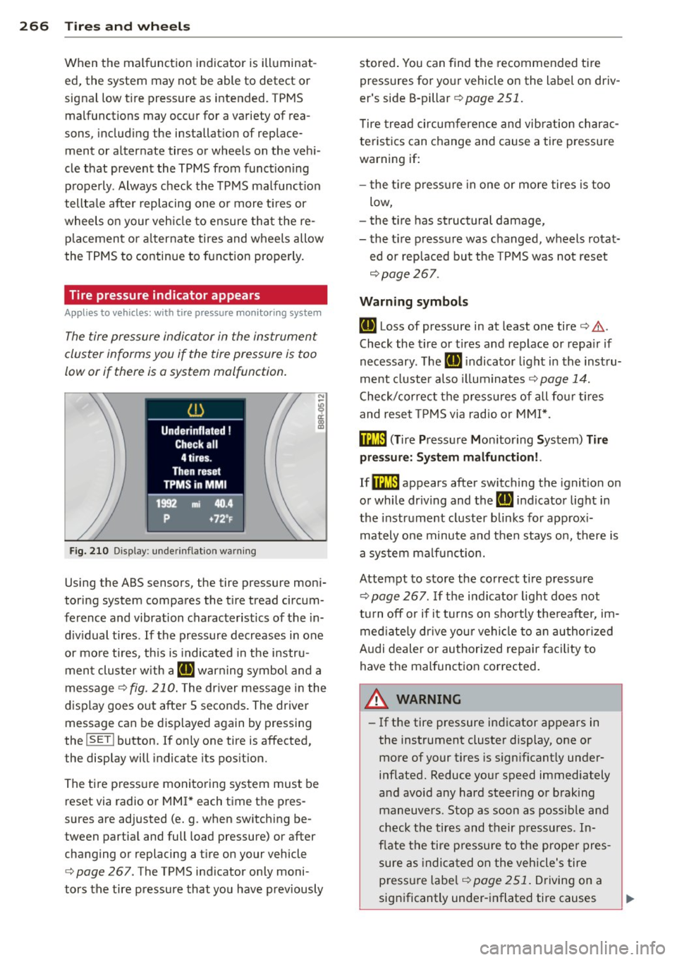
The tire pressure indicator in the instrument
cluster informs you if the tire pressure is too
low or if there is a system malfunction.
N
I
Fig. 210 Display: underinflation warning
Using the ABS sensors, the tire pressure moni
toring system compares the tire tread circum
ference and vibration characteristics of the in
dividual tires. If the pressure decreases in one
or more tires, th is is indicated in the instru
ment cluster w ith a
IE warning symbol and a
message
¢fig . 210. The dr iver message in the
display goes out after 5 seconds. The driver
message can be displayed again by pressing
the
! SET ! button. If on ly one tire is affected,
the display will indicate its position.
The tire pressure monitoring system must be
reset via radio or MMI * each time the pres
sures are adjusted (e. g . when switching be
tween partia l and full load pressure) or after
changing or replacing a tire on your vehicle
¢
page 267. The TPMS indicator only moni
tors the tire pressure that you have prev iously stored
. You can find the recommended tire
pressures for your vehicle on the label on driv
er's side B-pillar ¢
page 251.
Tire tread circumference and vibration charac
teristics can change and cause a tire pressure
warning if:
- the tir e pressure in one or more tires is too
low,
- the tir e has structural damage,
- the tir e pressure was changed, wheels rotat-
ed or replaced but the TPMS was not reset
¢page 267.
Warning symbols
IE Loss of pressure in at least one tire¢ .&..
Check the tire or tires and replace or repa ir if
necessary. The
IE indicato r light in the inst ru
ment cluster als o illuminates
¢ page 14.
Check/correct the pressures of all four tires
and reset TPMS via radio or MMI*.
ffim (T ire Pressure Mon itor ing System) Tire
pressure: System malfunction!.
If@m appears after switching the ignition on
or while dr iving and the
IE indicator light in
the instrume nt cluster blink s for app rox i
mately one minute and then stays on, there is
a system malfunction.
Attempt to store the correct tire pressure
¢
page 267 . If the indicator light does not
tu rn
off or if it turns on shortly thereafter, im
mediately drive you r vehicle to an authorized
A udi dealer or authorized repair facility to
have the malfunction corrected.
A WARNING
=
- If the tire pressure indicator appears in
the instrument cluster display, one or
more of your tires is sign ificant ly under
inflated. Reduce your speed immediately
and avoid any hard steer ing or braking
maneuvers. Stop as soon as possible and
check the tires and their pressures. In
flate the tire pressure to the proper pres
sure as ind icated on the vehicle's tire
p ressu re lab el¢
page 251. Driving on a
significantly under-inflated tire causes
Page 281 of 316
Fuses and bulbs
Electrical fuses
Replacing fuses
Fuses tha t have blown will have me tal s trips
that have burned through .
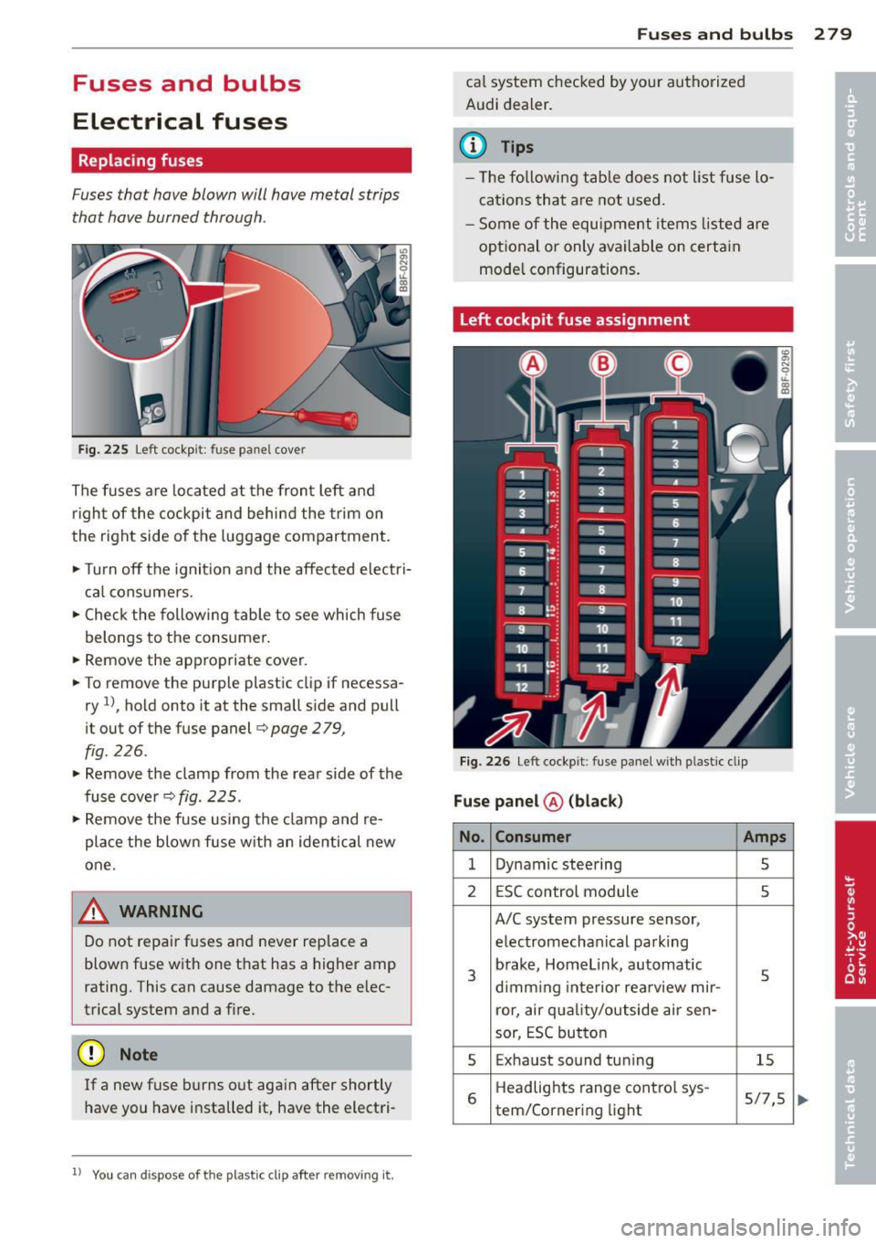
Fig . 225 Left cockp it : fu se pan el c over
The fuses are located at the front left and
r igh t of the cockpit and behi nd the trim on
the right side of the luggage compartment .
.. Turn
off the ignit ion a nd the affected electri
ca l consume rs .
.. Check the following table to see which fuse
belongs to the consumer .
.. Remove the appropriate cover .
.. To remove the purple plastic clip if necessa
ry
1 ), hold onto it at the small s ide and pull
it out of the fuse panel<=>
page 2 79,
fig . 226 .
.. Remove the clamp from the rear side of the
fuse cover
c> fig . 225 .
.. Remove the fuse using the clamp and re
place the blow n fuse w ith an identical new
one .
A WARNING
-
Do not repair f uses and never replace a
blown fuse w ith one t hat has a higher amp
rating. This can cause damage to the e lec
trical system and a fire.
(D Note
If a new fuse b urns o ut again after shortly
have you have installed it, have the electri-
11 You can dispo se of the pla stic cl ip aft er r emo vin g it.
Fu se s and bulb s 2 79
cal system checked by your authorized
Audi dealer .
a) Tips
- The followi ng ta ble d oes not list fuse lo
cations that are not used.
- Some of the equipment items liste d are
opt ional or only available on certain
mode l configurations .
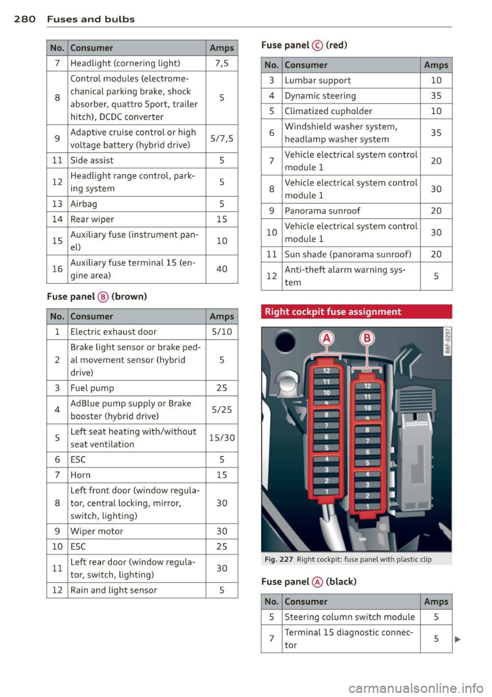
Left cockpit fuse assignment
Fig . 226 Le ft coc kp it : fuse p anel w ith pla st ic cl ip
Fu se panel @ (black )
No . Consumer Amps
1 Dynamic steering 5
2 E SC control module 5
A/C system pressure sensor,
e lectromechanical pa rk ing
3
b rake, Homelink, automatic
5 d imm ing interior rea rview mir -
ror, air qua lity/outside air se n-
sor, ESC but ton
5 Exhaust sound tun ing 15
6
Headlights range cont ro l sys -
5/7,5 tem/Corner i ng light
Page 282 of 316
280 Fuses and bulbs
No. Consumer Amps Fuse panel
© (red )
7 Headlight (corner
ing light)
7,5 No. Consumer Amps
Contro l modu les (e lec trome-
3 Lum bar s upport 10
8
chanic al par king br ake, sho ck
5
absorber, q uatt ro Spor t, tra ile r
hitch), DCDC converter 4
Dynamic stee ring
35
5 Climat ized cu pholder 10
9
Adaptive cruise contro l or hig h
5/7,5
vo ltage battery (hybr id d rive) 6
W indshield w asher system,
35
h eadlamp washer sys tem
1 1 Side ass ist 5
7 Vehicle e
lectrical system control
20
module 1
12 H
eadlight range contro l, par k·
5
ing sys tem
8
Ve hicle e lec tric al syste m control
30
mod ule 1
13 Airbag
5
9 Panorama sunroof
20
1 4 Rear wiper 15
1 5 Aux
iliary fuse (instrument pan·
10
el)
16
Auxi liary fuse term inal 15 (en -
40
gine area) 10
Vehicle e
lectrica l system control
30
module 1
1 1 Sun shade (panorama s unroof) 20
1 2 Anti-theft alarm warning sys·
s
tern
Fuse panel
@ (brown)
No. Consumer Amps Right cockpit fuse assignment
1 Electric exhaust door
5/10
Brake lig ht sensor o r brake ped·
2 al movem ent s ensor (hybrid 5
dr ive)
3 Fuel pump 25
4 AdBl
ue p ump supp ly o r Br ake
5/25
booste r (hybr id drive)
5 Left seat heati
ng wit h/w ithout
15/30
seat vent ilation
6 ESC 5
7 Horn 15
Left front door (window regula ·
8 tor, central locking, m irror,
30
sw itch, light ing)
9 Wipe r moto r 30
10 ESC 25
11 Le
ft r ear do or (win dow regul a-
30
t o r, sw itch, lighting)
12 Rain and light se
nso r
5
Fig. 22 7 Right cockp it: fuse panel wit h plast ic clip
Fuse panel ® (black)
No. Consumer Amps
5 Steering column sw itch mod ule s
7
Terminal 15 diagnostic connec·
tor
5
Page 300 of 316
298 Index .:..:..:..::....::.....:..._ ___________________________ _
A
Accessories . .. .. .. ..... ... .. .. .... . 295
AC (climate control) . . . . . . . . . . . . . . . . . . 80
Adapt ive cr uise control . . . . . . . . . . . . . . . 107
C leaning the sensor ....... .. .. .... . 218
Indica tor lamp . . . . . . . . . . . . . . . . . . . . 109
Messages .. ..... ........... ... .. . 114
Request fo r dr iver intervention . . . . . . . 11 2
Sett ing the d istance ........ ... .. ... 111
S ett ing t he d riving p rog ram .. .. .... . 112
Adapt ive dampers . . . . . . . . . . . . . . . . . . . 120
A dapt ive light . .. . ...... ... .. .. .... .. 51
D efective . . . . . . . . . . . . . . . . . . . . . . . . . 3 5
AdB lue .. .. .. ............. .. .. .. .. . 228
Fil ling . .. .... ........... .. .. .... . 229
M essages in the ins trument clus ter dis -
p lay .. ... ... .. .. ..... ... .. .. .... . 22 8
Adding Eng ine coolant ........... .. .. .... .
E ng ine oil ............... .. .. .. .. .
W indshie ld w asher fl uid ... .. .. .... .
Addit ional accesso ries
Additives 239
236
2 4 6
295
E ngine oil .... ........... .. .. .... . 236
Ad justing
A ir dist ribution ( clima te control) . ... . . 80
Fr ont seats .... . ...... ... .. .. .... .. 61
Steer ing column manually ... .. .. .. . . 83
Temperature (climate control) .. .... .. 80
A irbag sys tem . . . . . . . . . . . . . . . . . 1 57, 174
Advan ced Airbag Sys tem ... .. .. .. .. . 16 1
Advanced Airbag Sys tem components . 164
Ca re ..... .. ... .. ..... ... .. .. .... . 170
C hil dren . .... ........... .. .. .... . 179
C hi ld restra ints ............. .. .... . 180
Components (front airbags) .. .. .... . 164
Danger of fitt ing a child safety seat on
the front passenger seat ....... .. ... 158
Di sposa l . . . . . . . . . . . . . . . . . . . . . . . . . 170
Fr ont airbags . . . . . . . . . . . . . . . . 16 1, 16 2
H ow do the front airbags wo rk? . .... . 166
H ow ma ny airbags does my vehi cle
have? ...... .. .. ..... ... .. .. .... . 164
H ow t he A dvanced Airbag System com
ponents work together . . . . . . . . . . . . . 165
Important things to know .... .. .... . 157 Indicator lig
ht ... ... .. ..... .... . .. 168
Monito ring . ..... .. ... ..... ... .. .. 168
PASSENGER AIR BAG OFF light ... .. .. 168
Repairs ... .... .. ............. .... 170
Safety instr uctions ............. .... 170
S ide a irbags ..... ................ . 172
S ide cu rtain airbags .... .. ... ..... .. 175
Warning/ind icator lights ........... .. 16
We igh t-sensing mat ........... .. .. 179
When m ust t he sys tem be inspected? . 168
Air transport .. .. .. .......... ...... . 106
Alcantara Cleaning . ..... .. ... .. ..... .... . .. 220
All-wheel drive .. .. .. ........... .. .. 202
Se lective wheel torque con trol ... .... 19 7
Winter tires ..... .. ... ..... ... .. .. 262
Alternato r
Malfunction . . . . . . . . . . . . . . . . . . . . . . . 29
Anti-free ze
refer to Eng ine coolant system ... .... 238
An ti-l ock b rake system . .. ..... ... .. .. 197
Warning/ind icator lights . . . . . . . . . 15 , 17
Anti-s lip reg ulatio n ............. .. .. 19 7
Warning/ind icator lights ........ .. .. . 15
Anti-theft a larm warn ing system . ...... . 38
E lectronic immob ilizer ....... ...... .. 38
Approach/depa rture angle ..... ... .. .. 210
Ash tray .... .... ................... . 75
Asterisk What does it mean when something is marked wit h an aster isk? . . . . . . . . . . . . . . 6
Audi braking guard
refer to Braking guard .......... .. .. 113
Audi dr ive selec t
Indicator light ... .. ... ..... ... .. .. 2 01
also refer to Drive select ..... ... .. .. 120
Audi par king syste m plus with rearview
c amer a .. .. .. .. .. .... ......... .... 1 29
Adjus ting the d isplay ........... .. .. 133
Adjus ting the warning tones ... .. .. .. 133
Cleaning sensors/came ra lenses . ... .. 218
Rea rv iew camera - parking mode 1 . ... 132
Rea rv iew camera - parking mode 2 .. .. 132
Safety precautions ............. .... 129
Switching on and off ... .. ... ..... .. 131
T ra iler h itc h ..... ................ . 134