low beam AUDI Q5 2014 Owners Manual
[x] Cancel search | Manufacturer: AUDI, Model Year: 2014, Model line: Q5, Model: AUDI Q5 2014Pages: 316, PDF Size: 78.41 MB
Page 16 of 316
14 Instruments and warning/indicator lights
Warning/indicator lights
Overview
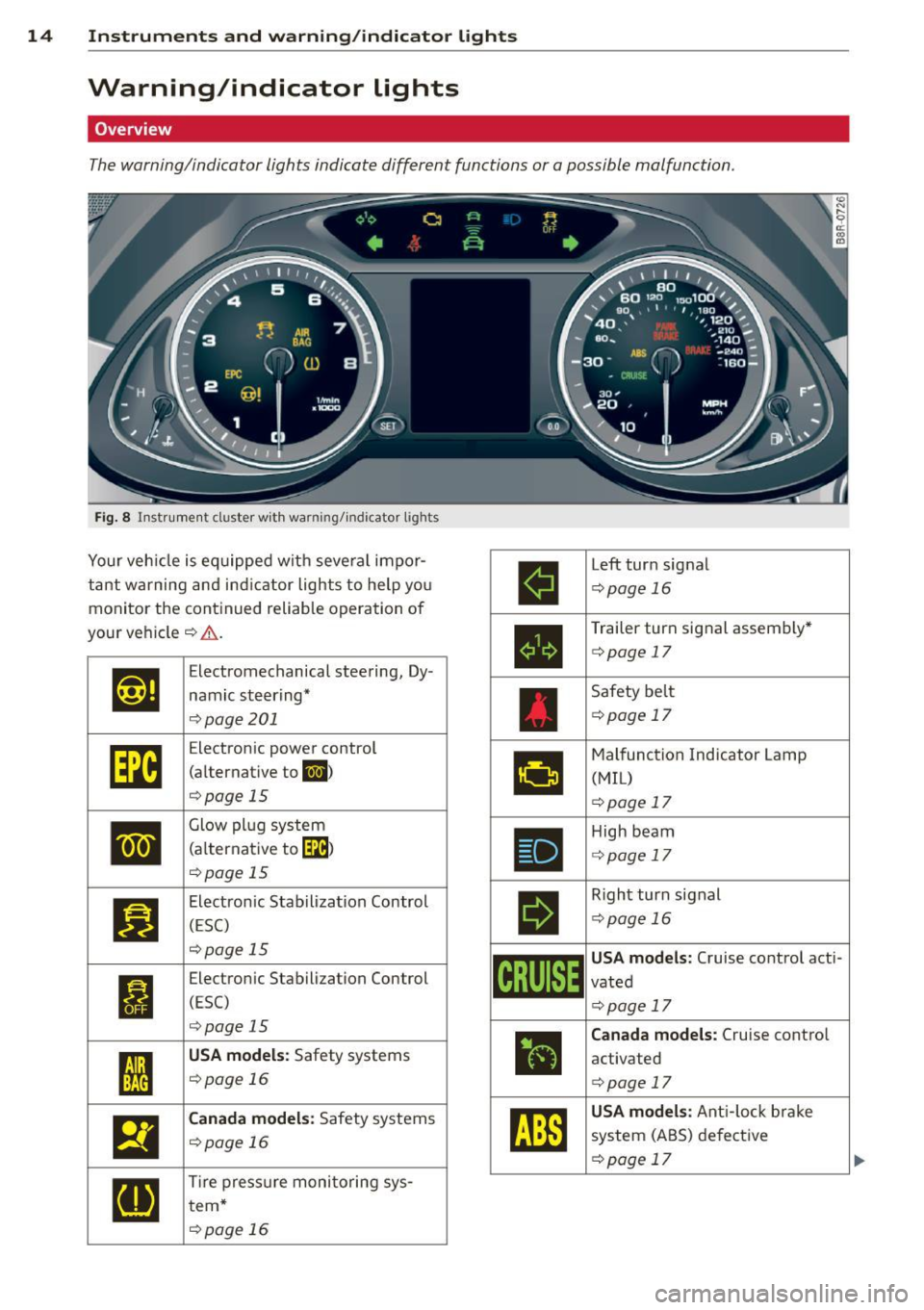
The warning/indicator lights indicate different functions or a possible malfunction.
Fig. 8 In str umen t cluster with warning/indicator lights
Your veh icle is equipped with seve ral impor
tant warning and indicator lights to help you
monitor the continued reliable operation of
your veh icle
c:> .&. .
Et·ff
Elect romechanical steering, Dy-
namic steering*
c:>pag e 201
[m
Electron ic power control
(alternative to
II)
c:>page 15
•
Glow plug system
(a lternat ive to
[IB)
c:>poge 15
II
Electronic Stabilization Control
(ESC)
c:>page 15
I
Electronic Stabilization Control
(ESC)
c:>page 15
I
USA models: Safety systems
c:>poge 16 .
El
Canada models: Safety systems
c:>page 16
[IJ
Tire pressure monitoring sys-
tern*
c:>poge 16
ll
Left turn signal
c:>page 16
•
Trailer turn signal assembly*
c:>page 17
Safety belt
c:>page 17
•
Malfunction Indicator Lamp
(MIL)
c:>page 17
•
High beam
<::>page 17
II
Right turn signal
<::>pag e 16
~i[~~1~
USA models: Cruise control acti-
vated
<::>pag e 17
ii
Canada models: Cruise control
activated
c:> page 17
~
USA models : Anti-lock brake
system (ABS) defective
c:> page 17
Page 35 of 316
-Ze Key not in vehicle
Applies to vehicles: with Convenience key
l!I Is the key in the vehicle?
This reminder appears along with the l!I sym
bol if the master key is removed from the ve
hicle with the engine running. It is intended
to remind you (e.g. when changing drivers)
not to continue the journey without the mas
ter key.
If the master key is no longer in the vehicle,
you cannot switch off the ignition after stop
p in g the engine and you also cannot start the
engine again . You also cannot lock the vehicle
from the outside.
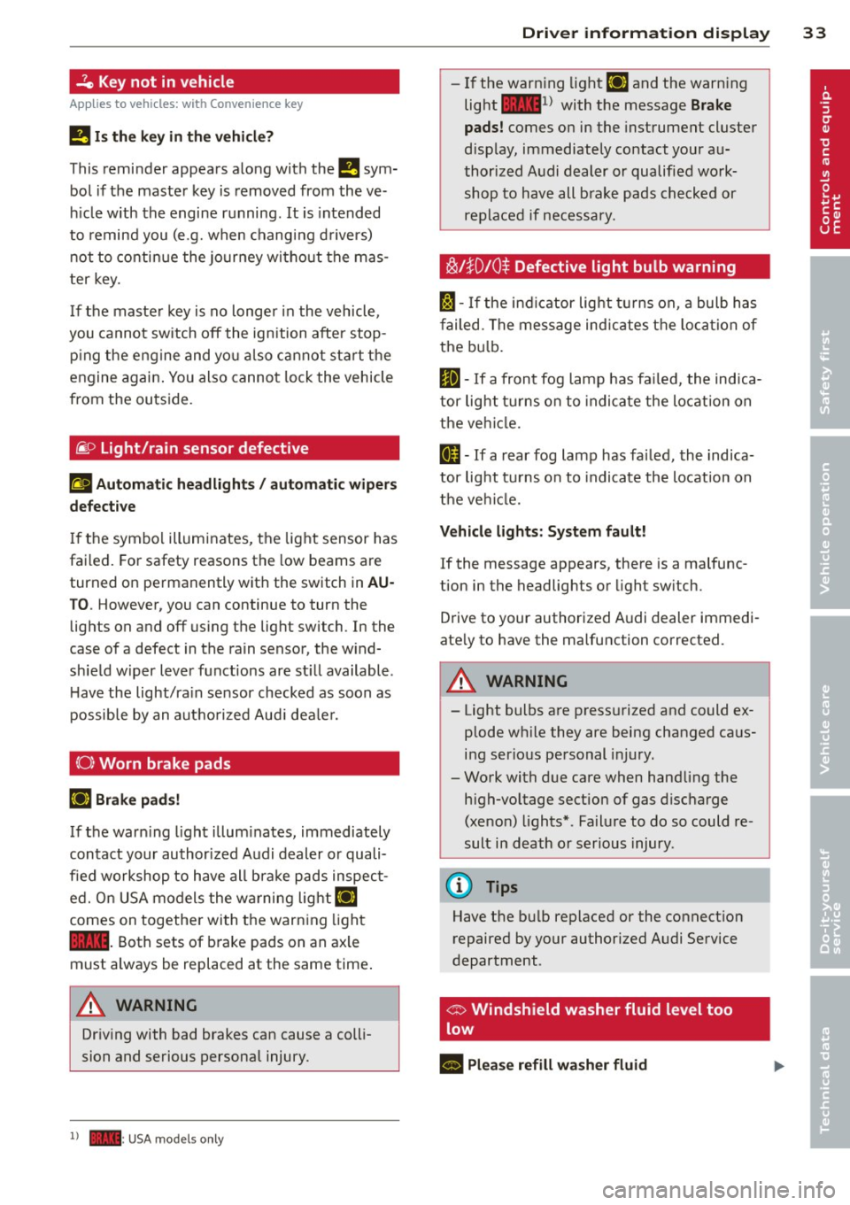
@9 Light/rain sensor defective
El Automatic headlights / automatic wipers
defective
If the symbol illuminates, the light sensor has
failed. For safety reasons the low beams are
turned on permanently with the switch in
AU
T O . However, you can continue to turn the
lights on and off using the lig ht switch. In the
case of a defect in the rain sensor, the w ind
shield w iper lever functions are st ill available.
H ave the light/ra in sensor checked as soon as
possible by an autho rized Aud i deale r.
(0) Worn brake pads
li1 Brake pads!
If the warn ing light illuminates, immediately
contact your authorized Audi dealer or quali
fied workshop to have all bra ke pads inspect
ed. O n USA models the warning
light lil
comes on together with the warning light
1111. Both sets of brake pads on an axle
must always be replaced at the same time .
A WARNING
Driving with bad brakes can cause a colli
sion and serious personal injury.
1) - : USA mod els only
-
Driver information display 33
-If the warning light li1 and the warning
light
llll1l with the message Brake
pads!
comes on in the instrument cluster
disp lay, immediately contact your au
thorized Audi dealer or qualified work
shop to have all brake pads checked or
replaced if necessary.
~!}010$ Defective light bulb warning
f:;:1-If the indicat or light turns on, a bulb has
fa iled. The message indicates the location of
the bulb.
II-If a front fog lamp has failed, the indica
tor light tu rns on to indica te the locat ion on
the vehicle.
0 -If a rear fog lamp has failed, the indica
tor light turns on to indicate the location on
the vehicl e.
Vehicle lights: System fault!
If the message appears, there is a malfunc
tion in the headlights or light switch.
Drive to your authorized A udi dealer immedi
ate ly to have the malfunction corrected.
A WARNING
- Light bulbs are press urized and could ex
plode wh ile they are being changed caus
ing serious personal injury.
- Work with due care when handling the
high-voltage section of gas discharge
(xenon) lights*. Failure to do so could re
sult in death or serious injury .
(D Tips
Have the bu lb replaced or the connect ion
repaired by your authorized Audi Service
department .
c> Windshield washer fluid level too
low
- Please refill washer fluid
Page 51 of 316
Clear vision Lights
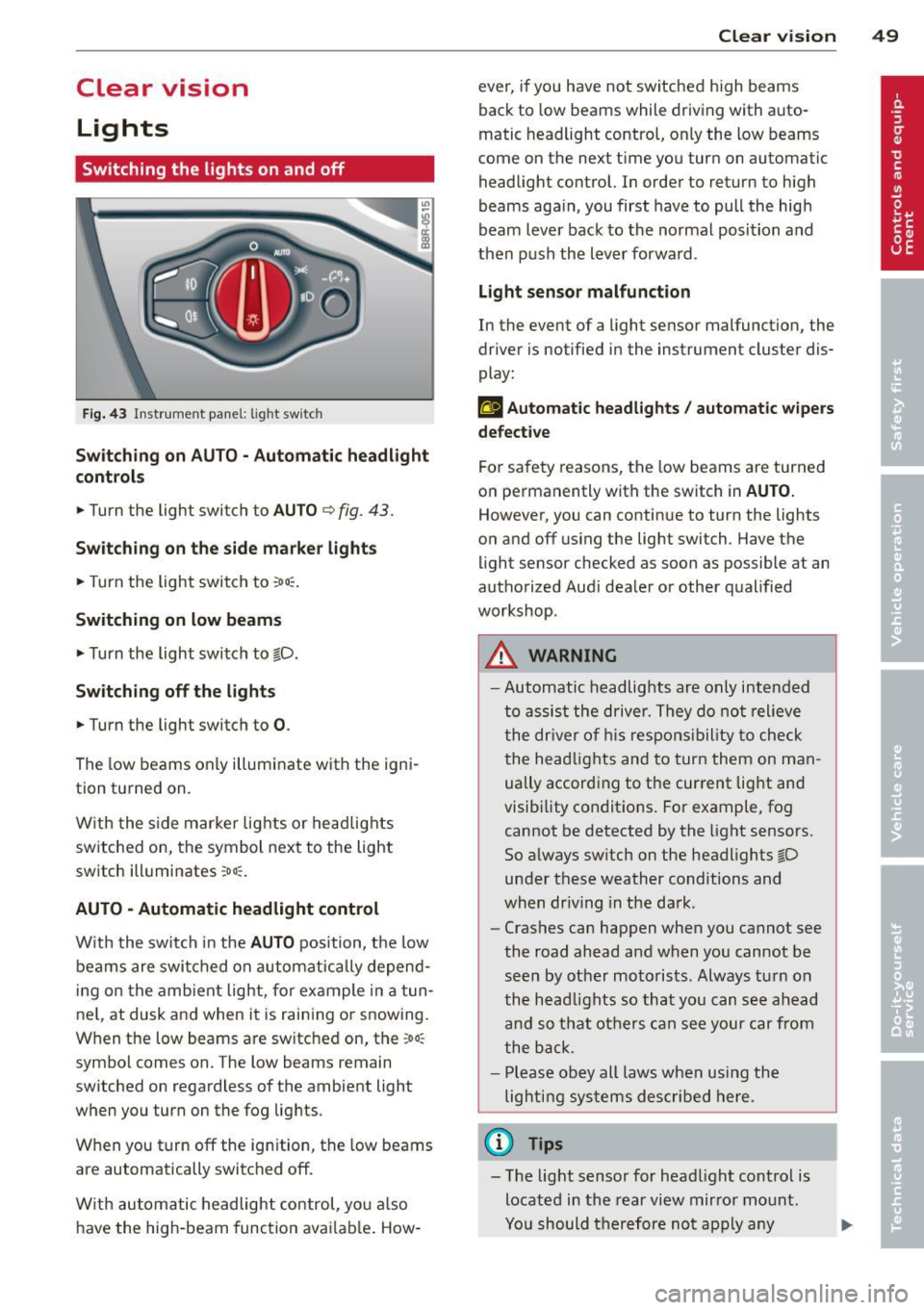
Switching the lights on and off
F ig . 43 Instrument pane l: light sw itch
Sw itching on AUTO - Automatic headlight
contr ols
• Turn the light switch to AUTO ¢ fig. 43.
Switchin g on the side m arker light s
• Turn the light switch to :oo:.
Switching on low beams
• Turn the light switch to @.D.
Swi tching off the lights
• Turn the light switch to 0 .
The low beams only illuminate with the igni
tion turned on.
With the s ide marker lights or headlights
switched on, the symbol next to the light
switch illuminates
:oo:.
AUTO -Automatic headlight control
With the switch in the AUTO position, the low
beams are swi tched on a utomatica lly depend
ing on the amb ient light, for example in a tun
ne l, at dusk and when it is raining or snowing.
When the low beams are switched on, the
:oo:
symbol comes on. The low beams remain
switched on regardless of the ambient light
when you turn on the fog lights.
When you turn
off the ign ition, the low beams
are automatically switched
off.
W ith automatic headlight control, yo u also
have the high-beam function avai lab le . How -
Clear vi sion 49
ever, if you have not switched high beams
back to low beams while driving with auto
matic headlight control, only the low beams
come on the next time you turn on automatic
headlight control. In order to return to high
beams aga in, you first have to pull the high
beam lever back to the normal position and
then push the lever forward .
Light sen so r malfunct ion
In the event of a light sensor malfunction, the
driver is notified in the instrument cluster dis
play :
fal Autom atic he adlights / autom ati c wi pers
defecti ve
For safety reasons, the low beams are turned
on permanently with the switch in
AUTO.
However, you can continue to turn the lights
on and
off us ing the light switch . Have the
light sensor checked as soon as possible at an
authorized Audi dealer or other qualified
workshop.
A WARNING
- Automatic headlights are only intended
to assist the driver. They do not relieve
the dr iver of h is respons ibility to check
the head lights and to turn them on man
ually accord ing to the current light and
visibility conditions. For example, fog cannot be detected by the light sensors.
So always sw itch on the headlights @.D
under these weather conditions and
when dr iv ing in the da rk .
- Crashes can happen when you cannot see
the road ahead and when you cannot be
seen by other motorists. Always tu rn on
the head lights so that you can see ahead
and so that others can see your car from
the back.
- Please obey all laws when using the
lighting systems described here.
(l'} Tips
- T he light sensor for head light control is
located in the rear view mirror mount.
Yo u should therefore not apply any
Page 52 of 316
50 Clear vis ion
stickers to the windshield in this area in
or der to prevent malfunctions or fai l
u res .
- Some exte rior lig hti ng f unctions can be
adjusted
c> page 50 .
-When yo u remove yo ur key from the igni
tion while the vehicle's lights are turned
on, a buzze r sounds as long as the driv
er's door is open .
- In coo l or damp weather , the ins ide of
the headlights, t urn signa ls and tail
li ghts can fog over due to the tempera
ture difference between the inside and
outside. They will clea r sho rtly after
switching them on . T his does not affect
the service life of the lighting .
- In the even t of a light sensor malfunc
t ion, the d river is no tified in th e inst ru
ment cluster disp lay
c> page 33.
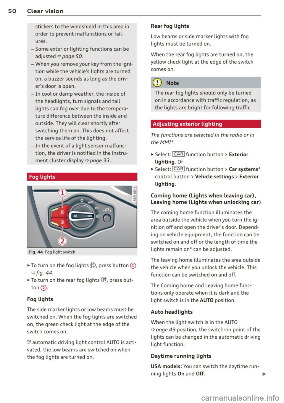
Fog lights
Fig . 44 Fog light sw it c h
.,. To turn on the fog lights }D, press button @
c>fig . 44 .
.,. To turn on the rear fog ligh ts 0$, p ress but-
ton @.
Fog lights
The s ide marker lig hts or low beams must be
switched on . When the fog lights a re switched
on, the green check light at the edge of the
sw itch comes on.
If automatic driving light control AUTO is act i
vated, the low beams are switched on when
the fog lights are tur ned on .
Rear fog lights
Low be ams o r sid e mar ker lig hts wi th fog
li gh ts m ust be t urned on .
When the rear fog lights a re turned on, the
yellow check ligh t a t the edge of the switch
comes on.
(D Note
The rear fog lights s houl d only b e turned
o n in acc ord ance wi th t raff ic reg ulation, a s
the lights are brig ht for following tra ffic.
Adjusting exterior lighting
The functions are sele cted in the radio or in
the MM I*.
.,. Select: I CAR I function button > Ext erior
lighting .
Or
.,. Sele ct: !CARlfunc tion button>
Car sy stem s*
contro l butto n > Vehicle setting s > Exterior
light ing .
Coming home (Lights when leaving car ),
Leaving home (Lights when unlocking car )
The coming home f unct ion ill umin ates the
are a outside the vehicle when you tu rn t he ig
nit ion off and o pen the d river's doo r. Depend
ing on vehicle equ ipment, the f unction can be
switched on and off or the length of t i me the
lights remain on* can be adjusted .
T he leaving home illum inates the area o utside
the ve hicle when you un lock the vehicle . This
funct ion can be switched on and off .
T he Comi ng home and Leaving home f unc
tio ns only ope rate when it is dark and the
light switch is in the
AUTO position .
Auto headlights
When the lig ht sw itch i s in the AU TO
c> page 49 position, the switc h-on point of the
li gh ts can be changed i n the automa tic driving
light function.
Daytime running lights
USA models: You can swi tch the daytime run-
ning lights
On and Off . .,..
Page 53 of 316
Canada models : The function cannot be
turned off.
It is activated a utomatica lly each
time the ignition is switched on.
Travel mod e (Canada models)*
The headlight beam is asymmetrical. This pro
vides stronge r illum ination on the s ide of the
road on which you are driving . If you are driv
ing in a co untry that drives on the opposite
side of the road from your own country, this
will cause glare for oncoming drivers. To pre
vent glare:
- Trave l mode must be selected in vehicles
with Xenon headlights*.
- In vehicles with halogen headlights, certain
areas of the head light lenses must be cov
ered with waterproof adhesive covers that
prevent light from passing through. For
more information, please see your author
ized Audi dealer or author ized repair facility .
@ Tips
When travel mode* is activated, a d isp lay
in the drive r information system ind icates
this each time you switch the ignit io n on .
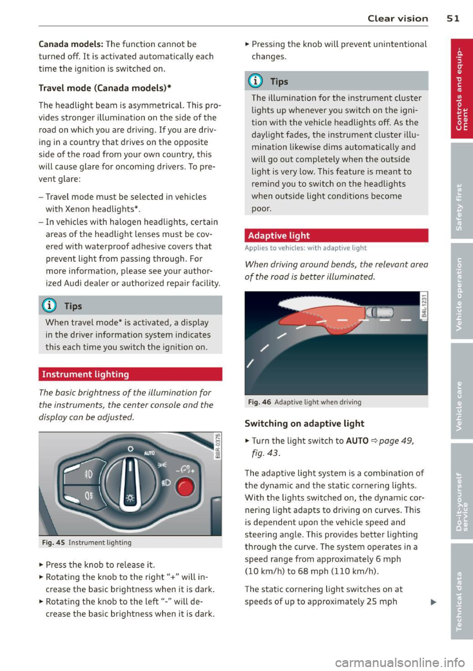
Instrument lighting
The basic brightness of the illumination for
the instruments, the center console and the
display can be adjusted .
Fig. 45 Inst rume nt lighting
.. Press the knob to release it.
.. Ro ta ting t he knob to the right" +" will in
crease the basic brightness when it is dark .
.. Rotating the knob to the left"-" will de
crease the basic br ightness when it is dark. Clear vi
sion 51
.. Pressing the knob will p revent unintentional
changes.
(D Tips
T he ill umination for the inst rument cluster
lights up w henever you switch on the igni
tion with the vehicle headlights off. As the
day light fades, the instrument cluster i llu
mination likewise dims automatically and
will go out completely when the outside light is very low. This feature is meant to
r emind you to switch on the head lights
whe n outs ide light conditions become
p oor .
Adaptive light
Applies to vehicles: wi th adaptive light
Wh en driving around bends, the relevant area
of the road is be tter illuminated.
Fi g. 4 6 Adapt ive light w hen driv ing
Switching on adapt ive light
.. Tu rn the light sw itch to AUTO ~ page 49,
fig. 43 .
The adaptive lig ht system is a combin ation o f
the dynam ic and the static corneri ng lights.
Wi th the lights switched on, the dynamic cor
ner ing light adapts to driving on curves. This
is dependent upon t he vehicle speed and
steering ang le. This provides better lighting
through the curve. The system operates in a
speed range from approximate ly 6 mph
(10 km/h) to 68 mph (110 km/h) .
The static cornering light switches on at
speeds of up to approximately 25 mph
Page 54 of 316
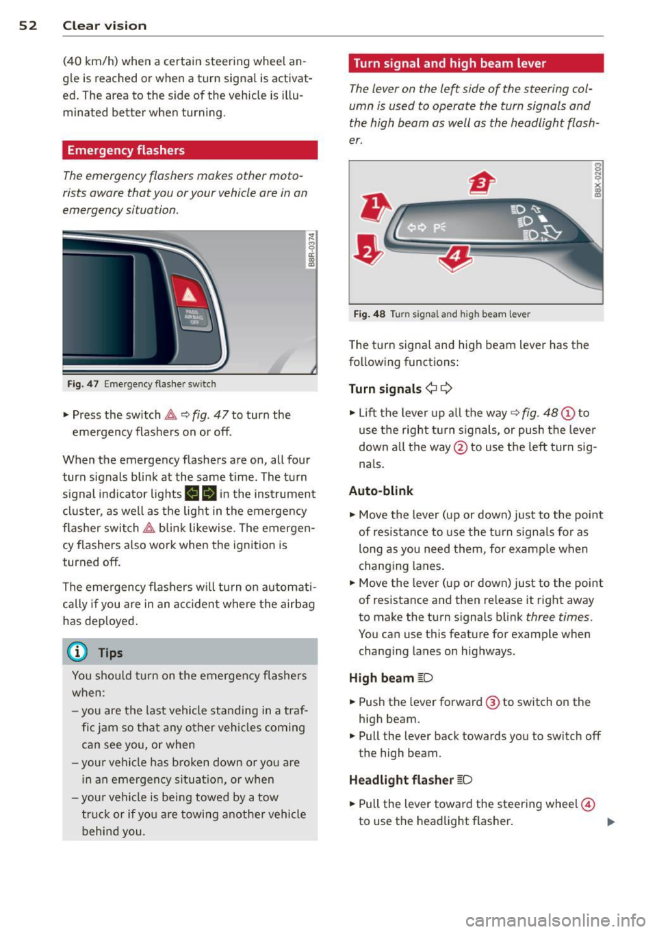
52 Clear vis ion
(40 km/h) when a certain steer ing whee l an
g le is reached or when a turn signa l is activat
ed . The area to the side of the vehicle is illu
minated better when turning .
Emergency flashers
The emergency flashers makes other moto
rists aware that you or your vehicle are in an
emergency situation.
Fig . 4 7 Eme rg ency flashe r switc h
"" Pr ess the switch ~ ~ fig. 47 to turn the
eme rgency flas hers on or off.
~
9 a: (X) a:,
When the emergency flashers a re on, all four
turn signals blin k at the same time. The tu rn
signal in dicator lights
BB in the ins trument
cluster, as we ll as the lig ht in t he emerge ncy
fla sher swi tch ~ blink likewise . T he emerge n
cy flashers also w ork whe n the ignition is
turned off.
The emergen cy flashers w ill turn on autom ati
cally if you are in an a cci den t w here the a irba g
has de ployed .
@ Tips
You shou ld tur n on t he emerge ncy fl ashe rs
w hen :
- you are the last vehicle st anding in a traf
fi c ja m so t hat an y oth er veh icles com ing
c an see you, or when
- you r vehicle has broken dow n or yo u are
in an emerge ncy si tu ati on, or when
- you r vehi cle is bei ng towe d by a tow
truck o r if you are towi ng an othe r vehicle
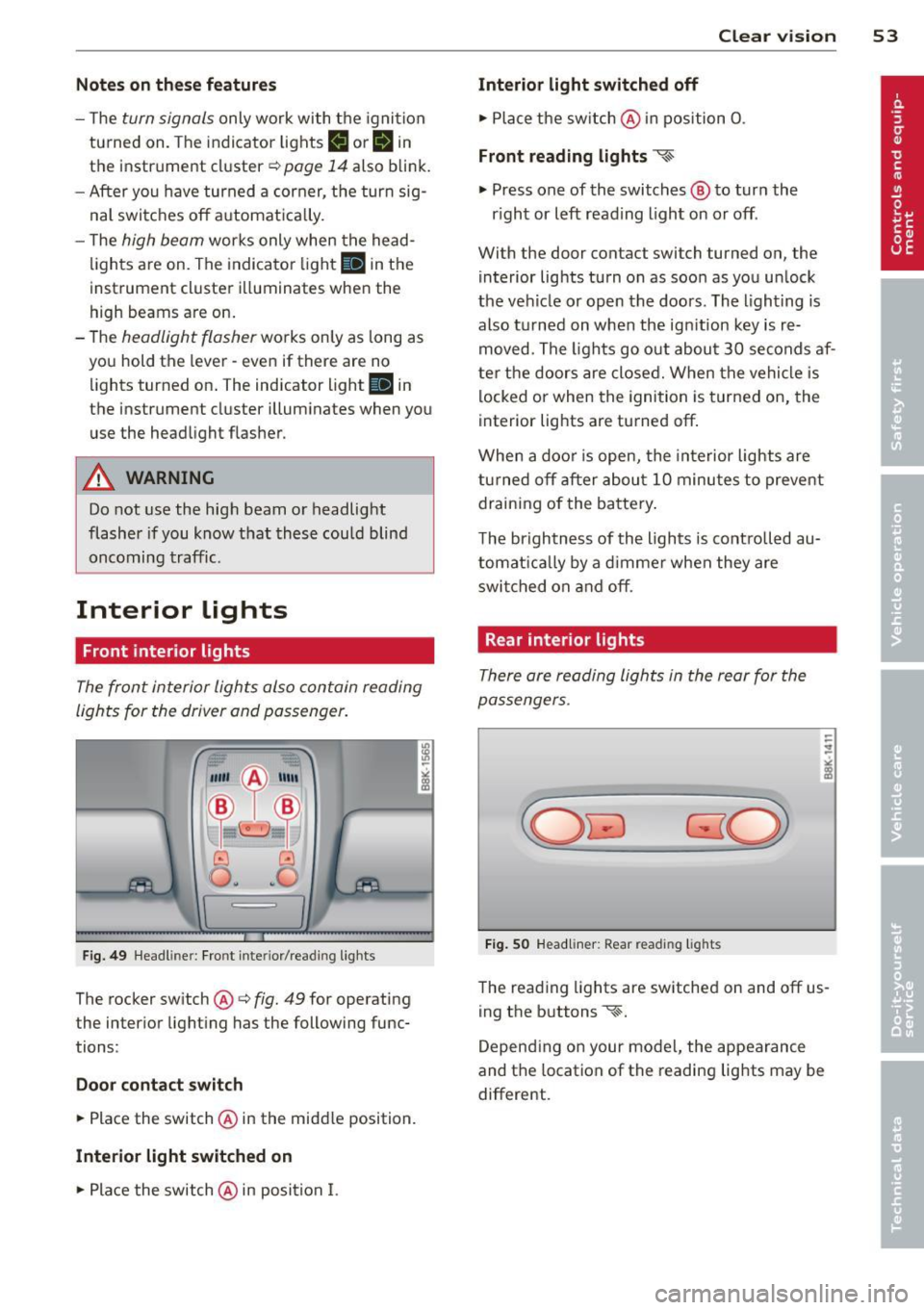
b ehin d you. Turn signal and high beam lever
The lever on the left side of the steering col
umn is used to operate the turn signals and
the high beam as w
ell as the headlight flash
er.
Fi g. 48 Tu rn signal and high beam lever
The turn signa l and high beam lever has the
fo llowing functions:
Turn signals ¢¢
s
"" '? X co a,
"" Lift the leve r up a ll th e way ~ fig. 48 (D to
use the right turn s ign als, or push the leve r
down a ll th e way @ to use the left tur n sig
n a ls.
Auto-blink .,. Move the lever (up or down) just to the point
of resistance t o use the tur n sign als fo r as
long as you need them, for e xamp le when
chang ing lanes .
.,. Move the lever (up or down) just to the point
of resistance and then re lease it rig ht away
to make the turn s ignals b link
three times .
You can use this featu re for example when
chang ing lanes on highways .
High beam
[D
"" Push the lever forward @ to switch o n the
high beam .
.,. Pull the lever back towards you to switch off
the high beam.
Headlight fla sher
[D
.. Pull the lever toward the steering wheel@
to use the headlight flasher .
IJJ>
Page 55 of 316
Notes o n these featur es
-The turn signals only work with the ignition
turned on. The indicator lights
II or Ill in
the instrument cluster
¢page 14 also b link.
- After you have turned a corner, the turn sig-
nal switches off automatica lly.
- The
high beam works only when the head
lights are on. The indicator light
II in th e
instrument cluster illuminates when the
high beams are on.
- The
headlight flasher wo rks only as long as
you hold the lever -even if there are no
lights turned on. The indicator light
II in
the instrument cluster illuminates when you
use the headlight flasher.
A WARNING
Do not use the high beam or headlight
flasher if you know that thes e cou ld blind
oncoming traffic.
Interior lights
Front interior lights
-
The front interior lights also contain reading
lights for the driver and passenger .
r ,,,,, , 11111
~8 ,~
G) Gl
,o . . o
I
Fig. 49 Headliner: Fro nt inte rior/rea ding lights
The rocker switch @¢ fig. 49 for operating
the interior lighting has the following func
tions :
Door cont act swi tch
.,. Place the switch @ in the midd le position.
Interior light switched on
.,. Pla ce the switch @ in position I.
Clear vision 5 3
Interior light swit ch ed off
.,. Place the switch @ in position 0 .
Front read ing lights ~
.,. Press one of the switches@ to turn the
r ight or left reading light on or off .
With the door contact switch turned on, the
interior lights turn on as soon as you unlock
the vehicle or open the doors. The lighting is
also turned on when the ignition key is re
moved. The lights go out about 30 seconds af
ter the doors are closed. When the vehicle is locked or when the ignition is turned on, the
interior lights are turned off.
When a doo r is open, the interior lights are
tu rned off after about 10 minutes to prevent
draining of the battery .
The brightness of the lights is controlled au
tomat ica lly by a d immer when they are
swi tched on and off.
Rear interior lights
There are reading lights in the rear for the
passengers .
Fig . 50 Headliner: Rear read ing lig hts
The read ing l ights are switched on and off us
ing the buttons ~-
Depending on your model, the appearance
and the location of the reading lights may be
different .
Page 94 of 316
92 On the road
Shift from D/S to P quickly to prevent the en
gin e from starting unintentionally when shift
ing through R.
You can dete rm ine fo r yoursel f if the eng ine
will stop or not by reducing o r increasing the
amo unt of force you use to press th e brake
pedal. For example, if you only lightly press
on the brake pedal in stop-and and -go traffic
o r when turning , the engine will not switch off
when the vehicle is stationary . As soon as you
press the brake down harder , the eng ine will
switch off.
(D Tips
- Press the brake pedal during a stop
phase to keep the vehicle from rolling .
- The ign ition will turn off if you press the
I S TART ENGINE STOP I* button dur ing a
stop phase .
- The image in the display is slightly differ
ent in some mode ls .
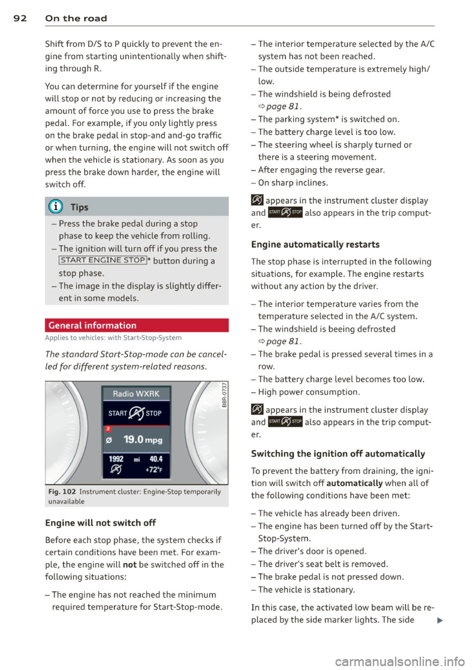
General information
App lies to vehicles: with Start -Stop -System
The standard S tar t-S top-mode can be cancel
led for different system -related reasons .
Fig. 1 02 Ins trument clust er: E ngin e-S top tempo rari ly
una va ilabl e
Engine w ill not switch off
Before each stop phase, the system checks if
ce rt a in cond itions have been met. For exam
ple, the engine w ill
not be sw itched off in the
following situations:
- The engine has not reached the min imum
required temperatu re for Start -Stop-mode. - The interior temperat
ure se lected by the A/C
system has not bee n reached.
- The outside tempe rature is extremely high/
low .
- The winds hield is being defroste d
o::::>pageBl.
-The parking sys tem* is switched on .
- The battery charge level is too low.
- The steering wheel is sharply turned or
there is a steer ing movement .
- After engaging the reverse gear .
- On sharp incl ine s.
er .
Eng ine automat ically r estarts
T he stop phase is interrupted in the follow ing
situations, fo r example . The engine restarts
without any action by the driver.
- The interior temperat ure varies from the
temperature se lected in the A/C system .
- The winds hield is bee ing defrosted
o::::> page 81.
- The b rake pedal is pressed severa l times in a
row.
- The battery charge level becomes too low .
- High power consumpt ion.
er .
Switching the ign ition off automatically
To p revent the battery from draining, the ign i
t ion w ill switch off
automatic ally when all of
the following conditions have been met :
- The vehicle has already been d riven .
- The engine has been turned off by the Sta rt-
Stop -System .
- The d river 's doo r is opened .
- The d river 's seat belt is removed .
- The brake pedal is not pressed down .
- The vehicle is stationary.
In this case, the activated low beam will be re-
placed by the side marker lights. The s ide ..,.
Page 306 of 316
304 Index
Heated (upho lder . .... . ...... ... .. .. .... .. 74
Exterior m irrors ... .... ... .. .. .... .. 57
Rear window ............. .... ...... 81
Seats .. ...... ........... ........ .. 81
Washer fluid nozz les . . . . . . . . . . . . . . . . 54
H eating ...... .. .. ..... ... .. .. .... .. 79
H eavy clothing and safety belts . .. ..... 1 52
High beam . .. ............. .. .. .. ... . 52
War ning/ indicato r lights ... .. .. .. .. . . 17
High voltage warning labe l .. .. .... .. . 289
H ill descent assist . . . . . . . . . . . . . . . . . . . 199
Hill descent control ........ .. .. .... . 126
H omelink (remote con tro l)
H ood 135
Opening . .. .. .. .. .......... ... .. . 23 1
Release lever . ........... .. .. .... . 23 1
Ho rn . .. ...... ........... .... .... .. . 8
H ow are c hild restra int sys tem anchors re -
l ated to child sa fe ty ..... ... .. .. .... . 19 1
H ow many airbags does my vehicle have? 164
How often sho uld I check my t ire pres-
sures? .. .. ................. .. .... . 254
H ow sa fety belt pretensioners wo rk ... . 1 55
H ybr id d rive .. .. .. ...... .... ... .. .. .. 97
12 vo lt batteries .... ... .. .. .. .. .. . 105
Consumpt io n disp lay ...... .. .. .... . 10 4
E fficien t drive mode ....... .. .. .... . 10 2
E ne rgy flow d isplay .. ... .. .. .. .... . 103
EV mode ... ... .. ..... ... .. .. .... . 100
H igh vo ltage battery . . . . . . . . . . . 97, 105
High vo ltage system .......... .. .. .. 97
Operating modes ......... .... .... . 100
Power meter . . . . . . . . . . . . . . . . . . . . . . . 98
Start ing the veh icle ...... ... .. .. .... 98
Transport . . . . . . . . . . . . . . . . . . . . . . . . 106
H ydroplaning ............... .. .... . 258
I
Ignition
Switching on/off . ..... ... .. .. .... .. 83
I gnition key
E mergency unloc king . . . . . . . . . . . . . . . . 3 8
Ignition lock . . . . . . . . . . . . . . . . . . . . . . . . 83
M alfunct io n . . . . . . . . . . . . . . . . . . . 31, 3 5
Important things to do before driving .. 139 Improperly worn sa
fety belts . ... .. .. .. 155
Ind icator lig hts . . . . . . . . . . . . . . . . . . 14 , 99
Airbag system ................ .... 168
P ASS ENG ER A IR BAG OF F ....... .. .. 168
Infant seats .. .. .. .... .... ..... .. .. 184
Inflatab le spare tire . .. .. ..... ... .. .. 269
I n flating . ..... .. .. ... ..... ... .. .. 270
Installing child safety sea ts
S af ety be lts . . . . . . . . . . . . . . . . . . . . . . 188
Installing the upper tether strap on the
ancho rage .. .. .. .. ... .. .. ... ..... .. 195
Instrument cluster .... .. ..... ... .. .. . 98
Instrument ligh ting ............. .... . 51
Instruments and controls ........ .. .. . 10
General illustration . . . . . . . . . . . . . . . . . . 8
Interior lights
Dimming .. ..................... .. . 53
Front . .. .. .... ............... ..... 53
Rea r ..... .. .. .. .. ........... .... . 53
Interval wiping .... ... .. ..... .... . .. . 54
Rain sensor . . . . . . . . . . . . . . . . . . . . . . . . 54
J
Jump-star ting 283
Jumper cables ... .. ... .. .. ... ..... .. 284
Jump start ing .................. .... 105
K
Key ... ... .. .... .. .. ... .. ..... ... .. . 36
Battery replacement . . . . . . . . . . . . . . . . 3 7
Check light . . . . . . . . . . . . . . . . . . . . . . . . 3 7
Emergency key . . . . . . . . . . . . . . . . . . . . . 85
Ig nit io n/engine o n/off .............. . 83
Key replacement . . . . . . . . . . . . . . . . . . . 36
Master key with remote control . . . . . . . 36
Mechan ica l key . .. .... .... ..... .. .. . 37
Removing . .. .. .. ... .......... .... . 85
K ick-down
t iptro nic .. .. .. .. ... .. .. ... ..... .. 127
L
Lane Change Assistant
refer to Side assist . . . . . . . . . . . . . . . . . 116
Page 307 of 316
-----------------------------~I~ n~d~ e~ x 305
LA T CH
D escr ipt io n . .... .. .... ... .. .. .. .. .
Install ing a chi ld restraint . ... .. .. .. .
Locat ion
Mounting and releas ing the anchorage
hook
. . ' .. ... ................ ... '
19 1
192
193
192
193
L ateral angle ... .... .... ... .. .. .. ... 2 10
Leather clean ing/protection . .. .. .. .. . 220
Lefthand drive ............ .... .. .. .. 51
Lifting jac k . . . . . . . . . . . . . . . . . . . . . . . . 2 7 s
Lifting vehicle ..... .. ...... .. .. .. .. . 287
Light
Com ing home ............ .... .. .... SO
Daytime running lights . . . . . . . . . . . . . . SO
Driving light control .............. ...
49
E me rgency flashers . . . . . . . . . . . . . . . . . 52
E xterior ligh ting . . . . . . . . . . . . . . . . . . . . SO
H igh bea m .............. .... .. ....
52
H igh be am war ning/ indica to r li ght ... .. 17
Leaving home . . . . . . . . . . . . . . . . . . . . . . so
Sensor ..... .. .. .. .. .... ... .. .. .... 4 9
Sensor defective ... .... ... .. .. .. .. .. 33
Sw itch ing on and off .. .... .. .. .. .. .. 4 9
Travel mode ........ ..... .... .. .. .. 51
Tu rn signa ls . . . . . . . . . . . . . . . . . . . . . . . 52
Loading the l uggage compa rtment .. .. . 14 5
Loc king
P owe r locking switch . ..... .. .. .. .. ..
42
R ea r li d/tr unk l id ..... .... .. .. .. .. .. 4 3
Remote cont rol key . . . . . . . . . . . . . . . . . 4 0
Using the mechan ica l key . ... .. .. .. .. 41
Low beams 4 9
Defect ive .. ............. .... .. .... 3 3
Lower universal anchorages (Canada) .. . 191
Luggage compartmen t ... ... .. .. .. .. .. 6 7
Ca rgo net .. .... .. .... ... .. .. .. .... 70
Cover .. .. .. .. .... .. .... ... .. .. .... 69
Expanding . . . . . . . . . . . . . . . . . . . . 6 7, 68
Storage hooks . . . . . . . . . . . . . . . . . . . . . 70
Stowing . . . . . . . . . . . . . . . . . . . . . . . . . 145
Tie -down r ings .................. ... 68
also refer to Loading the l uggage com-
pa rtment .. .... ... ... ... .... .. .. .
14 5
Luggage comp artment lid
Emergency unlocking ...... .. .. .. .. ..
45
Lumbar s upport . ... .... ... .. .. .. .... 6 2
M
Maintenance .. . ' .. ... .. .. ..... ... . . 2 93
Malfunction Ind icator Lamp (MIL) 17 , 26
Master key
Battery replacement .. ...... ..... .. .
37
Check lig ht .. .. .. ........ ..... .... . 37
Matte finish pain t clean ing .... ... .. .. 2 17
Mechan ica l key ...... ..... ........... 37
Memory for d river 's seat .... ......... . 63
Recalling set tings .... ............. . 63
Storing settings .. ... ... .... ... .. .. . 63
Mileage
Ave rage ... .. .. .... . ... ...... ... .. .
23
Instantaneous . .. ...... ..... ...... . 23
Mirro rs
Activatin g the dig it al compass ... .. .. .
59
Adjusting the exterior mirrors . . . . . . . . . 57
d. . 1mming .. .. .... ... .. .. ..... ... .. . 58
Moni to ring the Advanced Ai rbag System 168
N
Natura l leather
Cleaning
New tire s and wheels
N HT SA
Contacting . ..... ... .. .. ..... ... . .
N itrogen oxide (NOx) catalyt ic converte r
refer to Ad Blue . .. .... ...... ..... . .
Number of seat s
... .... ... .... .... ..
0
Occ upant seating positions
220
258
146
22 8
149
140
O cta ne rat ing . .. .. ...... ... .. .. .. .. 22 2
Odome ter . . . . . . . . . . . . . . . . . . . . . . . . . . 13
Offroad mode ........ .. .. ..... ... .. 198
OFF (climate co ntrol) .. .. .. ... ... .. .. . 80
Oil
refer to E ng ine oil 233,236
Oil consumpt ion ..... . .. .. ..... ... .. 236
On-Boa rd D iagnost ic System (O BD)
Data Link Connector ( DLC) .... ....... .
26
El ec tronic s peed limi ter ...... ... .. .. . 2 7
M alfunction I nd ic a tor Lam p (M IL) .. .. . 26
Onboard too l kit ... .. . .. ... .... ... .. 268
Open door o r rea r lid wa rning .. ... .. .. . 21
•
•