charging AUDI Q5 2017 Owners Manual
[x] Cancel search | Manufacturer: AUDI, Model Year: 2017, Model line: Q5, Model: AUDI Q5 2017Pages: 296, PDF Size: 74.43 MB
Page 108 of 296
Hybrid Energy flow display
Applies to: ve hicles w ith hybri d drive
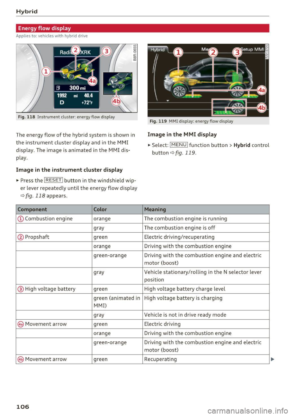
Fig. 118 Instrument cluster: energy flow display
The energy flow of the hybrid system is shown in
the instrument cluster display and in the MMI
d isplay. The image is animated in the MMI dis
play .
Image in the instrument cluster display
.. Press the I RESET I button in the windshie ld wip
er lever repeatedly until the energy flow display
r::> fig. 118 appears.
Component Color
@Combust ion engine orange
gray
@ Propshaft green
orange
green-orange
gray
@ H igh voltage battery green
green (animated in
MMI)
gray
@ Movement arrow green
orange green-orange
@ Movement arrow green
106
Fig. 119 MMI display: energy flow display
Image in the MMI display
.,. Select: !MENUI function button> Hybrid control
button
r::!) fig. 119 .
Meaning
The combustion engine is running
The combustion engine is off
Electric driving/recuperating
Driving with t he combustion engine
Driving w ith the combustion engine and electric
motor (boost)
Vehicle stationary/rolling in the N selector lever
position
High voltage battery charge level
High voltage battery is charging
Vehicl e is not in dr ive ready mode
Electric driving
Driving with the combustion engine
Driving with the combustion engine and electric
motor (boost)
Recuperating
Page 109 of 296
a,
a,
..... N ,-... N ..... 0 0
0:
co
@ Tips
The Energy flow display will not shown in the
MMI display when the reverse gear is engag
ed, due to safety reasons .
Consumption display
Applies to: vehicles with hybrid drive
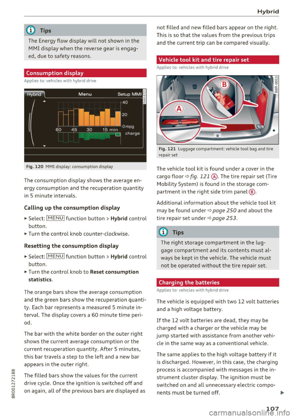
Fig . 1 20 MMI displa y: co nsump tio n dis play
T he consumption d isplay shows the average en
ergy consumption and the rec uperation quantity
i n 5 minute interva ls .
Calling up the consumption display
... Select : I MENU I function button> Hybrid control
button .
... Turn the cont rol knob co unter -clockwise.
Resetting the consumption displ ay
... Se lect : I MENU I function button > Hybrid cont rol
button .
... Turn the control knob to
Reset consumpt ion
stat ist ics .
The orange bars show the average consumption
and the green bars show the recuperation quanti
ty . Each bar represents a measured
5 minute in
terval. The display covers a
60 m inute time peri
od .
The bar w ith the wh ite border on the outer right
shows the current average consumption or the
cur rent recupe ration q uantity. After 5 minutes,
this bar trave ls a step to the left and a new bar
a p pears in the outer right .
The filled bars show the values for the curren t
drive cycle . Once the ignition is sw itched off and
on aga in, all of the prev ious bars are display ed as
H ybrid
not fi lled and new fi lled bars a ppear on the right.
T his is so t hat the values from the previous t rips
and the current trip can be compared v isua lly.
Vehicle tool kit and tire repair set
Applies to: vehicles with hybrid drive
Fig. 121 L uggage compar tm ent: ve hicle too l bag an d tir e
r epa ir set
The veh icle tool k it is fou nd u nder a cover in the
cargo floor
c::> fig. 121 @ . The ti re repa ir set (T ire
Mobility System) is fo und in the storage com
partmen t in the r ight side trim p anel @.
Additional informat ion about t he vehicle too l kit
may be found under
c::> page 250 and about the
t ir e repa ir set un der
c::> page 253 .
@ Tips
The right sto rage compartment in t he lug
gage compartment and its co nte nts must al
w ays be kept in the vehicle. The vehicle must
not be o per ate d w it h ou t the tire repair set.
Charging the batteries
Applies to: vehicles with hybrid drive
The vehicle is eq uip ped w it h t wo 12 volt ba tteries
and a high vo ltage battery .
If the 12 vo lt batte ries are dead, they may be
ch arged wi th a charger or the vehicle may be
j u mp s tarted wi th assis tan ce from ano ther veh i
cl e in the same way as a conventional vehicle.
T he same app lies to the hig h vol tag e batte ry if it
is d isch arged. However, in this ca se, the ch ar gin g
proces s is ac compa nied wi th messages in t he in
strument cl uster d is p lay . T he ignition mus t be
switched on and a ll unnecessary e lectric compo-
nents must be turned off . ""
107
Page 110 of 296
Hybrid
The connections in the engine compartment are
used for both charging and jump starting
c::> page 22 7 or c::> page 266.
Vehicle not ready to start. See owner's
manual
This message appears if the high voltage battery
charge level is too low. The vehicle can no longer
be started with its own power. The high voltage
battery must be charged with a charger or the ve
h icle must be jump started with the aid of anoth
er vehicle.
After the connecting the charger or jumper ca
bles, the ignition must be turned off for approxi
mately two minutes and then turned on again .
After no more than one m inute, one of the fol
lowing indicator lights turns on in the instrument
cluste r display .
B Charging battery. Please wait ...
If the indicator light turns on and this message
appears, the high voltage battery is charg ing or
the vehicle is be ing jump started with assistance
from another veh icle .
If the 12 volt batteries are dead, the- indi
cator light turns on . The charging procedure
takes longer in this case because the 12 volt bat
ter ies are charged first. The procedure goes fast
er with the ig nition sw itched off.
Vehicle ready to start.
This message appears if the charging procedure
was successful. The vehicle may be started again .
Battery could not be charged enough to start
vehicle .
This message appears if the charging procedure
was not successful or it was interrupted. Th is
may happen if the charger or the battery in the
veh icle that is assisting is too weak.
If the veh icle
can not be started, see an authorized repa ir facil i
ty for ass istanc e.
(D Tips
-The charger should deliver a current of at
l east 30 A. Otherwise charging the high
voltage battery will take considerably Ion-
108
ger. A current between 50 A and 70 A is ide
al.
- Th e veh icle that is assisting should be some
what within the same vehicle class when
jump starting a vehicle. A smaller vehicle's
battery may be drained.
- After approximately 30 minutes, the charg
ing procedure ends because the ignit ion is
automatically turned off. If you would like
to cont inue to charge the battery, turn the
ignition on again.
Vehicle transport
App lies to: vehicles wit h hybrid drive
The following contains information you should
know about transporting your vehicle.
The lithium ion battery (SANYO 72 UF 121 285)
installed in your vehicle has passed test 38.3 in
accordance with UN handbook tests and criteria.
The vehicle may be transported with the battery
i nstalled as conventional class 9 hazardous mate
rials without addit ional officia l consent for a ir
and sea transportation (current law !CAO-TI and
IMDG-Code 01.01.2012).
Page 229 of 296
a,
a,
..... N
" ('I ..... 0 0
0:
co
,&_ WARNING
California P roposition 65 Warn ing :
- B attery posts, termi na ls and re lated acces
sories contain lead and lead compounds,
chemicals known to the State of California
to cause cancer and reproductive problems.
Wash hands after handling.
(D Note
- Do no t disconnect the ve hicle bat tery when
t h e ignit ion is switched on or when the en
gine is runni ng, otherwise, you w ill damage
electron ic components in the e lectr ica l sys
tem.
- If your vehicle is going to stan d for a long
period of time without be ing driven, protect
the battery from "freez ing", otherwise it
will be damaged a nd will then have to be re
placed .
Battery charging
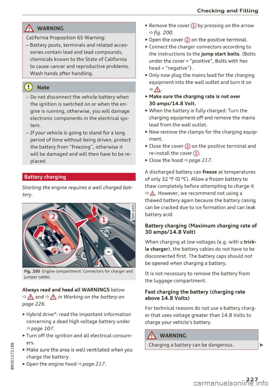
Starting the engine requires a well charged bat
tery .
Fig. 200 Engin e co mpartme nt: Co nnectors for charger and
j um per ca bles
Always read and heed all WARNINGS below
c> & and <=> & in Working on the battery on
page 226 .
.. Hybrid dr ive*: read the important i nformation
co ncerning a dead high voltage battery under
<=> page 107.
.. Turn off the ignition and all e lectr ica l consum
ers.
.. Make s ure the a rea is well vent ilated w hen you
c harge the b attery.
.. Open the engine hood
c> page 217 .
Checking and Filling
.. Remove the cover@ by pressing on the arrow
<=>fig . 200.
.. Open the cover @on the pos itive terminal.
.. Connect the charger connecto rs according to
the instructions to the
jump start bolts . (Bolts
under the cover = "positive" , Bolts w ith hex
head = "n egative ").
.,. Onl y now plug the mains lead for the cha rgi ng
equ ipme nt in to the wa ll ou tlet and turn it on
<=> & .
.. Make sure the charging rate i s not over
30 amps/14.8 Volt.
.. When the battery is fully charged: Turn the
charging equ ipment off and remove the ma ins
lead from the wall out let .
.,. Now remove the clamps for the charg ing equip
ment .
.,. Close the cover @on the pos it ive termina l and
re- insta ll the cover
(D .
.,. Close the hood c> page 217.
A d ischarged battery can freeze at temperat ures
of on ly 32 °F (0 °C). Allow a frozen batte ry to
t h aw comple tely before attempting to charge it
c> .&, . However, we recommend not using a
t h awe d batt ery ag ain be ca use the bat tery ca sing
can be cracked due to ice formation and ca n leak
batte ry ac id.
Battery charging (Maximum charging rate of
30 amps/14.8 Volt)
W hen charging a t low voltages (e.g . w ith a trick
le charger ),
th e battery cables do not have to be
disconnected first. The battery caps should
not
be opened when cha rging a battery.
It is no t necessary to remove the bat tery from
the luggage compartment .
Fast charging the battery (charging rate
above 14 .8 Volts)
F or technical rea sons do not use a batte ry charg
er that uses vo ltage greater than 14.8 Vo lts to
c h arge your veh icle's battery .
A WARNING
-Charging a battery can be dangerous.
227
Page 230 of 296
Checking and Filling
-Always follow the operating instructions
provided by the battery charger manufactur
er when charging your battery.
- Never charge a frozen battery . It may ex
plode because of gas trapped in the ice. Al
low a frozen battery to thaw out first.
- Do not reuse batteries which were frozen .
The battery housing may have cracked and
weakened when the battery froze .
- Charge the battery in a well ventilated area.
Keep away from open flame or electrical
spark . Do not smoke. Hydrogen gas generat
ed by the battery is explosive .
- To reduce the danger of explosion, never
connect or disconnect charger cables while
the charger is operating .
- Fast charging a battery is dangerous and should only be attempted by a competent
technician with the proper equipment .
- Battery acid that may spill during charging should be washed off with a solution of
warm water and baking soda to neutralize
the acid.
(D Note
Never use a fast charger as a booster to start
the engine. This will seriously damage sensi
tive electronic components, such as control
units , relays , radio, etc., as well as the battery
charger.
Battery replacement
The new battery must have the same specifica
tions and dimensions as the original equipment
battery.
Intelligent energy management in your vehicle is
responsible for distributing the electrical energy
throughout your vehicle
~ page 192. The intelli
gent energy management system will keep the
engine battery charged better then vehicles with
out this system. To mak e sure the additional
electrical energy is available once again after you
have changed the battery, we recommend that
you install batteries of the same type and manu facture only (the same as those installed at the
time your vehicle was delivered) . Specifications
228
are listed on the battery housing. Your author
ized dealer must cod e the battery in the energy
management system to enable you to use the en
ergy management functions correctly after re
placing the battery.
If it is not possible to use a battery of this type,
the new battery must have the same capacity,
voltage (12 volts), amperage, construction and plug sealing.
When installing the battery, make sure the igni
tion and all electrical consumers are turned off.
([) Note
- Make sure the ventilation hose on the side
of the battery is connected, otherwise
fumes or battery acid can leak out.
- Vehicles with the Start-Stop-System* are
equipped with a special cycle-proof AGM
battery. Installing a different type of bat
tery can cause problems in the vehicle elec
trical system. When replacing the vehicle battery, always install one with the same
specifications as the original battery.
@ For the sake of the environment
Because of the problem of proper disposal of
a battery, we recommend your authorized
Audi dealer change the battery for you. Bat
teries contain sulfuric acid and lead and must
always be disposed of properly in compliance
with all environmental regulations. Disposing
of vehicle batteries improperly is
very danger
ous to the environment.
Page 283 of 296
Automatic transmission . . . . . . . . . . . . . . . . . 94
Automatic Shift Lock (ASL) . . . . . . . . . . . . . 95
Driving . . . . . . . . . . . . . . . . . . . . . . . . . . . . . 96
Emergency mode . . . . . . . . . . . . . . . . . . . . . 98
Emergency release . . . . . . . . . . . . . . . . . . . . 99
H ill descent control . . . . . . . . . . . . . . . . . . . 97
Kick-down . . . . . . . . . . . . . . . . . . . . . . . . . . . 98
Manual shift program . . . . . . . . . . . . . . . . . 98
Removal lock (ignit ion key) . . . . . . . . . . . . . 81
Selector lever . . . . . . . . . . . . . . . . . . . . . . . . 94
Shift paddles . . . . . . . . . . . . . . . . . . . . . . . . 98
Automatic wipe/wash system . . . . . . . . . . . . 54
Auto Safety Hotline . . . . . . . . . . . . . . . . . . . 138
AUTO (climate control) . . . . . . . . . . . . . . . . . . 78
Average speed . . . . . . . . . . . . . . . . . . . . . . . . 19
Avoid damaging the vehicle . . . . . . . . . . . . . 195
B
Bass box . . . . . . . . . . . . . . . . . . . . . . . . . . . . 251
Battery . . . . . . . . . . . . . . . . . . . . . . . . . . . . . 225
Battery location inside the luggage compart
ment .. .. .. .. ...... ......... .. .. .. . 225
Charge level . . . . . . . . . . . . . . . . . . . . . . . . 192
Charging . .. .. ............... .. . 107,227
Energy management . . . . . . . . . . . . . . . . . 192
Impor tant warnings when working on the
battery . . . . . . . . . . . . . . . . . . . . . . . . . . . . 225
Jump starting . . . . . . . . . . . . . . . . . . . . . . . 266
Replacing the battery . . . . . . . . . . . . . . . . 228
Voltage . . . . . . . . . . . . . . . . . . . . . . . . . . . . . 30
Winter operation . . . . . . . . . . . . . . . . . . . . 225
Working on the battery . . . . . . . . . . . . . . . 225
Before driving . . . . . . . . . . . . . . . . . . . . . . . . 131
Belt tensioners . . . . . . . . . . . . . . . . . . . . . . . 146
Bio-ethanol (Fuel)....... ..... ... ... .. . 210
Blended gasoline . . . . . . . . . . . . . . . . . . . . . 209
Blower (climate control) . . . . . . . . . . . . . . . . 78
Booster seats . . . . . . . . . . . . . . . . . . . . . . . . 176
B ra ke fluid
Changing the brake fluid . . . . . . . . . . . . . . 224
Checking the brake fluid l evel . . . . . . . . . . 224
Brake system
Anti-lock brake system . . . . . . . . . . . . . . . . 14
~ Brak e booster . . . . . . . . . . . . . . . . . . . . . . . 190 ....
~ Brake fluid . . . . . . . . . . . . . . . . . . . . . . . . . 224
8 Brake fluid specifications for refill and re-
~ placement . . . . . . . . . . . . . . . . . . . . . . . . . 224 00
Index
Brake light defective . . . . . . . . . . . . . . . . . . 29
Brakes . . . . . . . . . . . . . . . . . . . . . . . . . . . . . 190
Electromechanical parking brake . . . . . . . . 86
Fluid reservo ir . . . . . . . . . . . . . . . . . . . . . . 224
Malfunction . . . . . . . . . . . . . . . . . . . . . . . . . 25
Warning/indicator lights . . . . . . . . . . . . . . . 15
Worn brake pads symbol . . . . . . . . . . . . . . . 29
Braking Brake assist . . . . . . . . . . . . . . . . . . . . . . . . 186
Braking guard . .. . ... ............. 109, 115
Messages . . . . . . . . . . . . . . . . . . . . . . . . . . 116
Settings . . . . . . . . . . . . . . . . . . . . . . . . . . . 116
Switching on and off . . . . . . . . . . . . . . . . . 116
Break -in per iod
Brake pads . . . . . . . . . . . . . . . . . . . . . . . . . 190
Ti res . . . . . . . . . . . . . . . . . . . . . . . . . . . . . . 194
Breaking in . . . . . . . . . . . . . . . . . . . . . . . . . . 194
New tires . . . . . . . . . . . . . . . . . . . . . . . . . . 237
Breakover angle . . . . . . . . . . . . . . . . . . . . . . 198
Bulbs . . . . . . . . . . . . . . . . . . . . . . . . . . . . . . . 264
C
Californ ia Proposition 65 Warning 218
Battery specific . . . . . . . . . . . . . . . . . . . . . 227
Capacities . . . . . . . . . . . . . . . . . . . . . . . . . . . 273
AdBlue . . . . . . . . . . . . . . . . . . . . . . . . . . . . 214
Engine oil ....... .. ................. 219
Care . . . . . . . . . . . . . . . . . . . . . . . . . . . . . . . . 204
Cargo area
refer to Loading the luggage compart-
ment...... ... . ... ................. 136
Cargo floor . . . . . . . . . . . . . . . . . . . . . . . . . . . 68
Catalytic converter . . . . . . . . . . . . . . . . . . . . 194
Cente r armrest
Adjusting . . . . . . . . . . . . . . . . . . . . . . . . . . . 65
Storage compartment . . . . . . . . . . . . . . . . . 65
Centra l locking . . . . . . . . . . . . . . . . . . . . . . . . 35
Certification . . . . . . . . . . . . . . . . . . . . . . . . . 279
Changing Engine oil . . . . . . . . . . . . . . . . . . . . . . . . . . 222
Child restraints
Danger of using child restra ints in the front
seat...... .... .. .. ............... .. 149
System anchors . . . . . . . . . . . . . . . . . . . . . 181
Where can I get additional information
about child restraints and their use? . . . . 185
281