instrument cluster AUDI Q5 2017 Owners Manual
[x] Cancel search | Manufacturer: AUDI, Model Year: 2017, Model line: Q5, Model: AUDI Q5 2017Pages: 296, PDF Size: 74.43 MB
Page 9 of 296
CD
CD
.... N ,-... N ..... 0 0 C<'. 00
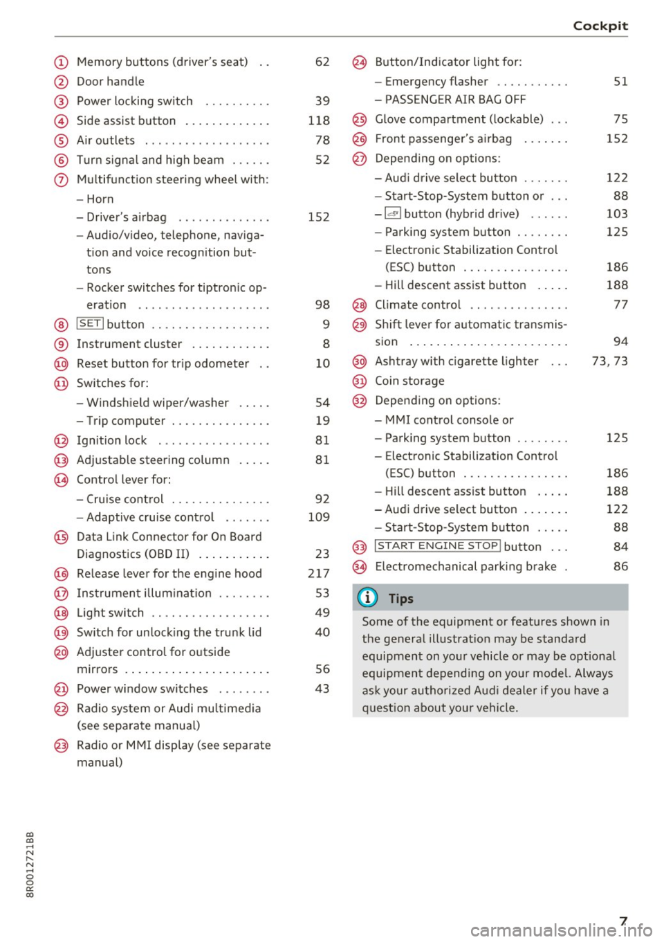
(!) Memory buttons (driver's seat)
@ Door handle
@ Power locking switch ......... .
© Side assist button ............ .
® Air outlets ..... ........ .... . .
@ Turn signal and high beam ... .. .
(j) Multifunction steering wheel with:
- Horn
- Driver's airbag ............ . .
- Audio/video, telephone, naviga-
tion and voice recognition but
tons
- Rocker switches for tiptronic op-
eration .. ............ ..... .
@ ISETI button ............... .. .
® Instrument cluster ........... .
@ Reset button for trip odometer
@ Switches for:
- Windshield wiper/washer
- Trip computer ............ .. .
@ Ignition lock ................ .
@ Adjustable steering column
@ Control lever for:
- Cruise control ............ .. .
- Adaptive cruise control ...... .
@ Data Link Connector for On Board
Diagnostics (OBD II) .......... .
@) Release lever for the engine hood
@ Instrument illumination ..... .. .
@ Light switch ............... .. .
@) Switch for unlocking the trunk lid
@ Adjuster control for outside
mirrors ..................... .
@ Power window switches ....... .
@ Radio system or Audi multimedia
(see separate manual)
@ Radio or MMI display (see separate
manual) 62
39
118
78
52
152
98
9
8
10
54
19
81
81
92
109
23
217
53
49
40
56
43
@ Button/Indicator light for:
- Emergency flasher .......... .
- PASSENGER AIR BAG OFF
@ Glove compartment (lockable) ...
@ Front passenger's airbag
@ Depending on options:
- Audi drive select button ...... .
- Start-Stop-System button or .. .
- Id'! button (hybrid drive) ..... .
- Parking system button ....... .
- Elect ronic Stabilization Control
(ESC) button . .............. .
- Hill descent assist button .... .
@ Climate control .. ............ .
@ Shift lever for automatic transmis-
sion ....... .. .............. .
@ Ashtray with cigarette lighter
@ Coin storage
@ Depending on options:
- MMI control console or
- Parking system button ....... .
- E lectronic Stabilization Control
(ESC) button . .. ............ .
Cockpit
51
75
152
122
88
103
125
186
188
77
94
73, 73
125
186
- Hill descent assist button . . . . . 188
-Audi drive select button . . . . . . . 122
- Start-Stop-System button . . . . . 88
@ I START ENGINE STOP! button . . . 84
@> Electromechanical parking brake 86
(D Tips
Some of the equipment or features shown in
the general illustration may be standard
equipment on your vehicle or may be optional
equipment depending on your model. Always
ask your authorized Audi dealer if you have a
question about your vehicle.
7
Page 10 of 296
Instruments and indicator lights
Instruments and indicator Lights
Instruments
Instrument cluster and controls
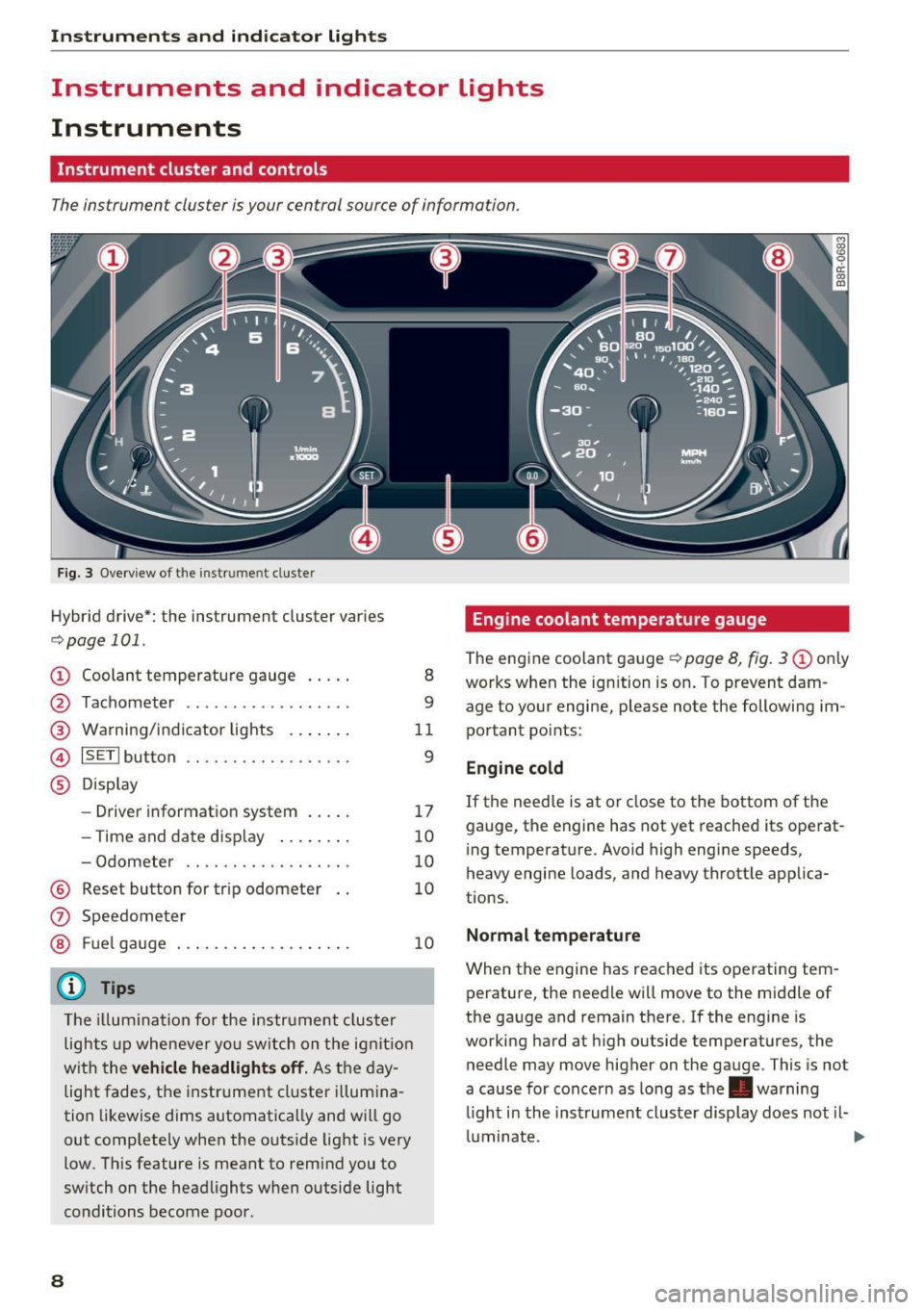
The instrument cluster is your central source of information.
Fig. 3 Overview of the instr ume nt cluste r
Hybrid drive*: the instrument cluster varies
c:;,page 101.
CD Coolant temperature gauge
@
®
©
®
Tachometer .............. ... .
Warning/indicator lights ...... .
ISETI button .... .. .. ..... .... .
Display
- Driver information system .... .
- T ime and date display ....... .
- Odometer .... .... ....... .. .
® Reset button for trip odometer
(J) Speedometer
® Fuel gauge
(D Tips
The illum inatio n for the instrument cluster
lights up whenever yo u switch on the ignit ion
w ith the
vehicle headlights off. As the day
light fades, the instrument cluster illumina
tion likewise dims automatica lly and will go
out comp letely when the outside light is very
low . This feature is meant to remind you to
switch on the headlights when outside light
conditions become poor .
8
8
9
11
9
17
10
10
10
10
Engine coolant temperature gauge
The engine coolant gauge¢ page 8, fig. 3 CD on ly
works when the ign ition is on . To prevent dam
age to your engine, please note the following im
portant points:
Engine cold
If the needle is at or close to the bottom of the
gauge, the engine has not yet reached its operat
ing temperature. Avoid high engine speeds,
heavy engine loads, and heavy throttle applica
tions .
Normal temperature
When the engine has reached its operating tem
perature, the needle will move to the middle of
the gauge and remain there.
If the engine is
working hard at high outside temperatures, the
needle may move higher on the gauge . This is not
a cause for concern as long as the . warning
li ght i n the inst rument cluste r display does not il-
luminate . ..,.
Page 11 of 296
a,
a,
..... N r-N ..... 0 0
0:
co
Warning light in the instrument cluster
display
If the . warning light in the instrument cluster
display flashes, this can mean one of two things:
either the coolant
temperature is too high, or the
coolant
level is too low~ page 26.
If the needle is well in the upper area of the
gauge, the coolant temperature is too high.
Stop
the vehicle, switch the engine off, and allow it
to cool. If the warning light comes on again after
driving a short distance, contact an authorized
Audi dealer or other qualified workshop .
_& WARNING
- Always observe the warning in~ page 217,
before opening the hood and checking the
engine coolant level.
- Never open the engine hood if you see or
hear steam, or if you see engine coolant
dr ipping from the engine compartment. You
cou ld burn yourself. Let the engine cool off
first so that you cannot hear or see any
steam or engine coo lant.
CD Note
- Mounting additional lights or accessories in
front of the air inlets reduces the cooling ef
fect of the radiator. At high outside temper
atures or high engine load, the engine could
overheat.
- The front spoiler has been designed to prop
erly distribute the cooling air when the vehi
cle is moving. If the spoiler is damaged, this
could reduce the cooling effect and the en
gine could then overheat. Ask your author
iz ed Audi dealer for assistance.
Tachometer (engine rev counter)
The tachometer indicates the engine RPM (revo
lutions per minutes) .
If engine RPM drops below 1,500, you should
downshift to the next lower gear. The red area at
the end of the scale indicates max imum permis
sible engine RPM after the break-in period . Be
fore reaching this area, move the selector lever
Instruments and indicator lights
to posit ion D/S or ease your foot off the accelera
tor pedal.
CD Note
The tachometer need le@ ~ page 8, fig. 3
shou ld only briefly be in the red zone: you
could damage your engine! The beginning of
the red zone varies depending on the engine.
@ For the sake of the environment
Upshifting early saves fuel and reduces en
gine noise.
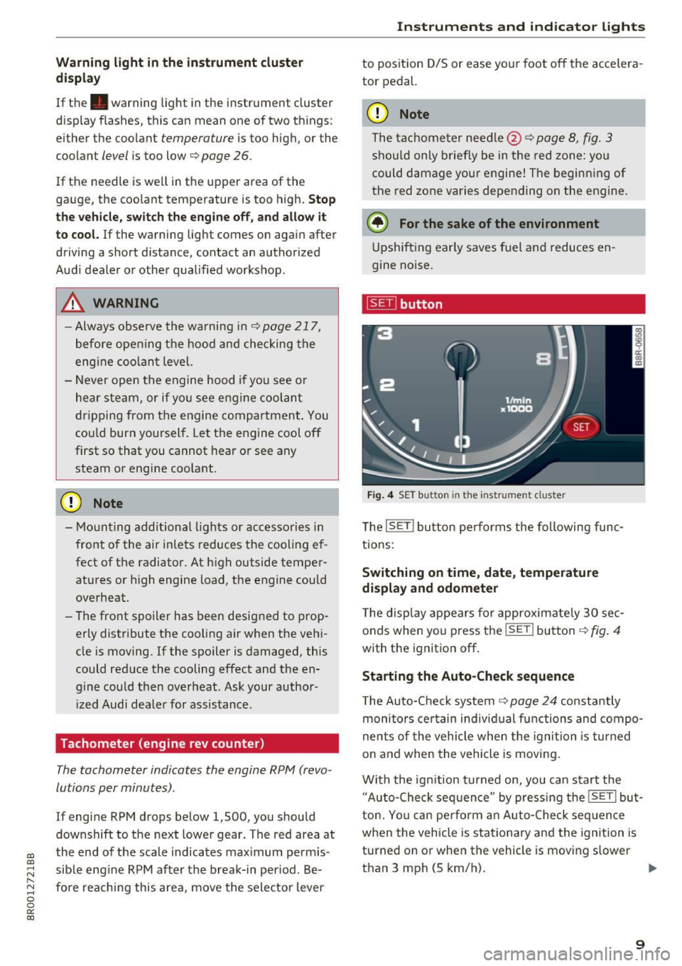
~ button
Fig. 4 SET button in the instrument cluster
The !SET ! button performs the following func
tions:
Switching on time, date, temperature
display and odometer
The display appears for approximately 30 sec
onds when you press the
ISETI button ~fig . 4
with the ignition off .
Starting the Auto-Check sequence
The Auto-Check system ~ page 24 constantly
monitors certain individual functions and compo
nents of the vehicle when the ignition is turned
on and when the vehicle is moving.
With the ignit ion turned on, you can start the
"Auto-Check sequence" by press ing the
!SE TI but
ton. You can pe rform an Auto-Check seq uence
when the vehicle is stationary and the ignition is
turned on or when the vehicle is moving slower
than 3 mph (5 km/h).
IIJ,,,
9
Page 12 of 296
Instruments and indicator lights
The number of keys programmed to the vehicle is
also displayed. The display
L2 3/3 in dicates that
three keys have been programmed. This a llows
you to make sure you have received all of the keys
when you purchase a used vehicle.
For examp le, if you on ly receive two keys, you
should take those keys to your authorized Audi
dealer to have the missing key deactivated so it
cannot be used. You should also report the miss
ing key to your insurance company .
Calling up the driver information
A yellow or red symbol appears in the instrument
cluster display, usually with a driver message.
The driver message display disappears after about 5 seconds. The dr iver message can be dis
played again by briefly pressing the
ISETI button.
Setting the speed warning
By pressing the !SET ! button briefly, you can set
thresho ld
1 of the speed warning while you are
driving
c::;,page 92. By maintaining pressure on
the
! SET I button, you delete the warning thresh
old.
Digital clock with date display
Depending on the vehicle equipment level, you
may choose between the quartz clock or the
GPS
controlled clock* l!j in the radio or in the MMI* .
You can learn more about this in the MMI manual
or in the radio user's manual.
(Di Tips
-When you sw itch off the ignition or open
the driver door, the time, date, odometer
and temperature are displayed for an addi
tiona l
30 seconds.
- You can also call up the display with the
ISET I button c::;, page 9 while the ignition is
switched
off.
Fuel gauge
The fuel gauge works only when the ignition is
on.
When the needle reaches the reserve mark, the
c::;, page 30 Ii') symbol appears in the instru-
10
ment cluster display as well as the message
Please refuel. This message is meant to remind
you to
refuel.
The total tank capacity of your ve hicle is listed in
¢ page 273.
(D Note
Never run the tank completely dry! An ir regu
lar supply of fuel can cause engine misfiring
and fuel could enter into the exhaust system.
The catalytic converter could then overheat
and be damaged.
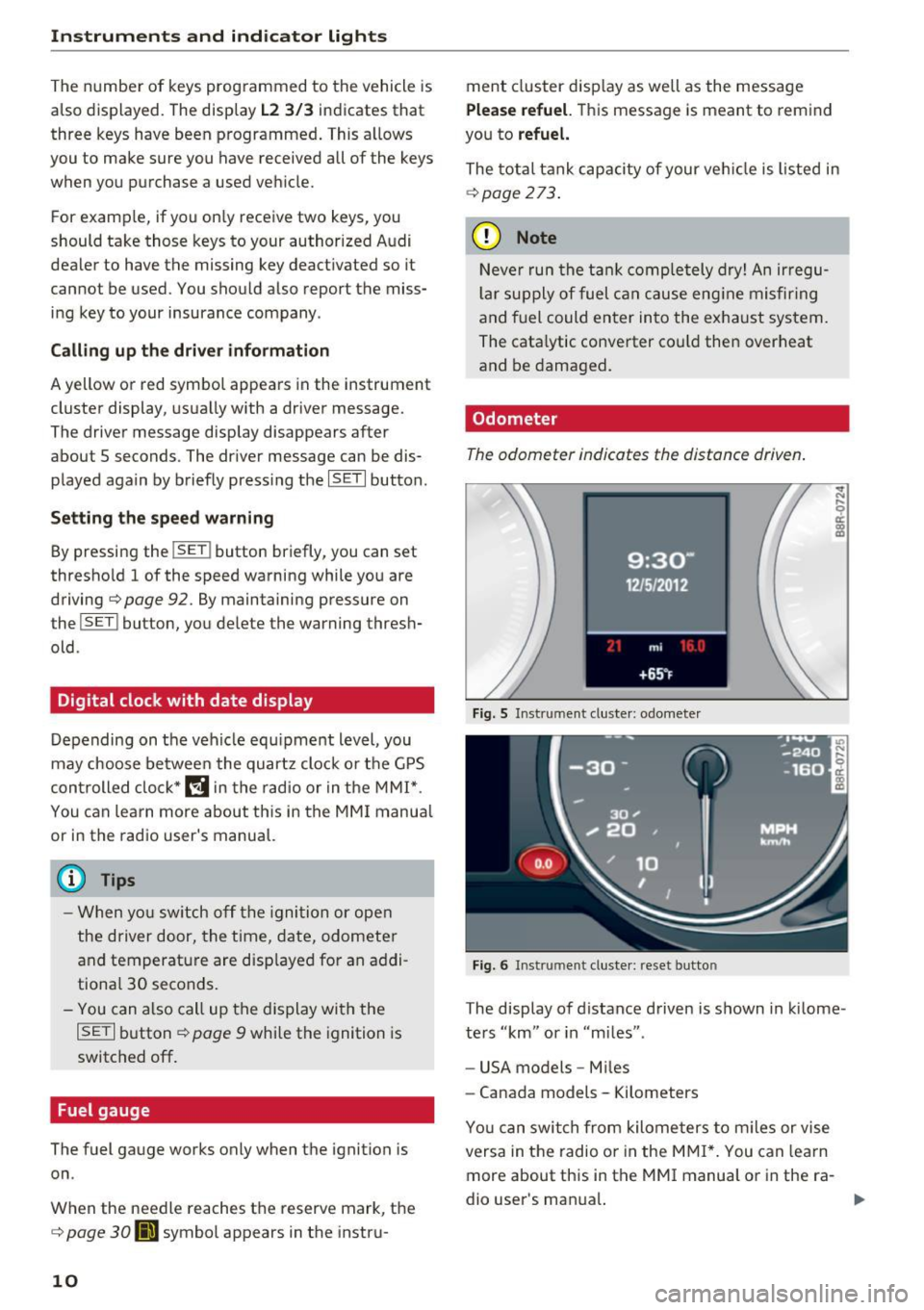
Odometer
The odometer indicates the distance driven.
Fig. 5 Instrument cluster: odometer
Fig. 6 Instrument cluster: reset button
The display of distance driven is shown in kilome
ters "km" or in "m iles".
- USA models -Miles
- Canada models - Kilometers
Yo u can switch from kilometers to miles or vise
versa in the radio o r in the MMI*. You can lea rn
more about this in the MMI manual or in the ra
dio user's man ual.
Page 13 of 296
a,
a,
..... N
" ('I ..... 0 0
0:
co
Odometer/trip odometer
The odometer shows the total number of kilome
ters or miles that have been driven on the vehi
cle.
The trip odometer shows the distance driven
since it was last reset . It can be used to measu re
short distances. The last digit shows distances of
100 meters or 1/10 of a mile.
The t rip odometer can be reset to zero by press
ing the reset bu tton
IO.OI ¢ fig. 6.
Malfunction message
If there is a malfunct ion somewhere in the in
strument cluster,
dEF will appear in the tripod-
Indicator lights
Overview
Instruments and indicator lights
ometer and will stay on. Contact your authorized
Aud i dealer to have the problem corrected.
(D Tips
-When you switch off the ign ition or open
the driver door, the time, date, odometer
and temperature are displayed for an addi
tional 30 seconds.
- You can also call up the display with the
!SET ! button¢ page 9 while the ignition is
switched off.
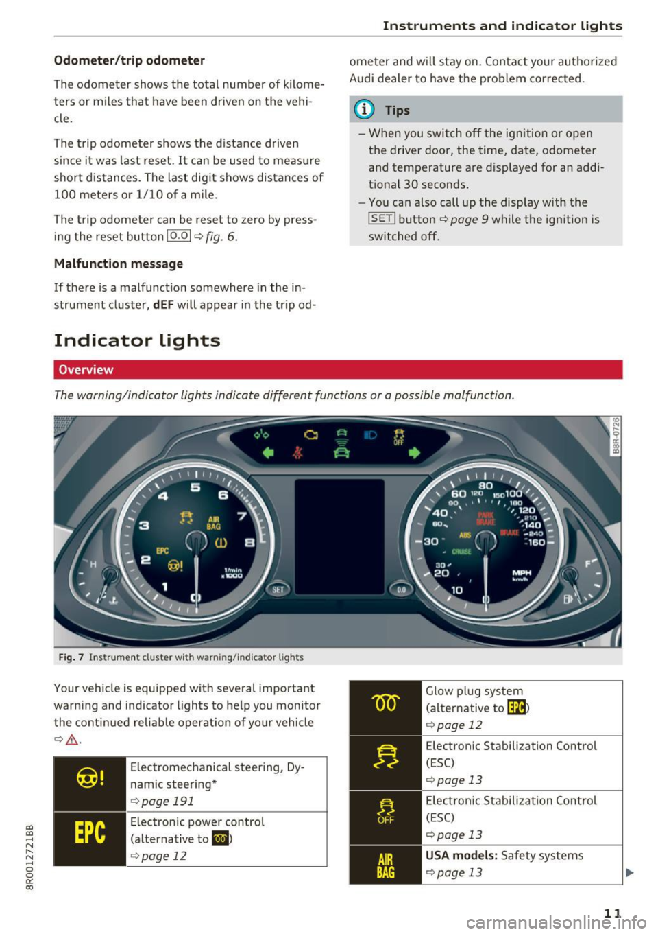
The warning/indicator lights indicate different functions or a possible malfunction.
Fig. 7 Ins trument cl uster wi th wa rning/in dicator lights
Your vehicle is equipped with several important
warning and indicator lights to help you monitor
the continued reliable operation of your vehicle
¢ .&,.
Electromechanical steering, Dy
namic steering*
c:> page 191
Electronic power control
(alternative to
&I )
~ page 12 Glow
plug system
(alternative to~
¢ page 12
Electronic Stabilization Control
(ESC)
c:>page 13
Electronic Stabilization Control
(ESC)
c:> page 13 USA model s: Safety systems
c:> poge 13
11
Page 19 of 296
a,
a,
..... N r-N ..... 0 0
0:
co
Driver information
system
Introduction
General notes
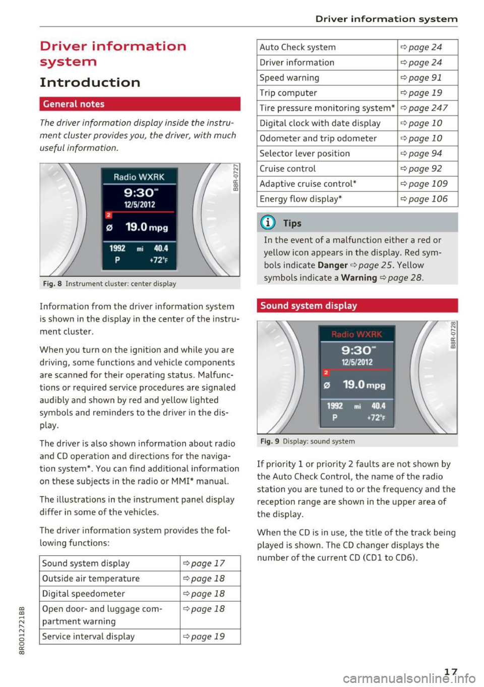
The driver information display inside the instru
ment cluster provides you , the driver, with much
useful information.
Fig. 8 Instrument cl uster : ce nt er display
Information from the driver information system
is shown in the display in the center of the instr u
ment cluster.
When you turn on the ignition and while you are
driving, some functions and vehicle components
are sca nned for their operat ing status. Malfunc
tions or required service procedures are signaled
audibly and shown by red and yellow lighted
symbols and reminders to the driver in the dis
play.
The driver is also shown information about rad io
and CD operat ion and directions for the naviga
tion system*. You can find addit ional information
on these subjects in the radio or MMI* manual.
The illustrations in the instrument panel display
differ in some of the vehicles .
The driver information system provides the fol
lowing functions:
Sound system disp lay
c:> page 17
Outside air temperature c:>page 18
Digital speedometer c:>page 18
Open door- and luggage com-c:> page 18
partment warning
Service interval display
c:> page 19
Driver in forma tion system
Auto Check system c:>page24
Driver information c:>page 24
Speed warning c:>page 91
Trip computer c:>page 19
Tire pressure monitoring system* c:>page247
Digital clock with date display c:>page 10
Odometer and trip odometer c:>page 10
Selector lever position c:> page 94
Cruise control c:>page92
Adaptive cruise control* c:>page 109
Energy flow display* c:>page 106
(D Tips
In the event of a malfunction either a red or
yellow icon appears in the display. Red sym
bols indicate
Danger c:>page 25. Yellow
symbols indicate a
Warning c:> page 28.
Sound system display
Fig. 9 Display: sou nd system
l!3 .... 0 er. m m
If priority 1 or pr iority 2 faults are not shown by
the Auto Check Control, the name of the radio
station you are tuned to or the frequency and the
reception range are shown in the upper area of
the display .
When the CD is in use , the tit le of the track being
played is shown. The CD changer disp lays the
number of the current CD (CDl to CD6).
17
Page 21 of 296
a,
a,
..... N r-N ..... 0 0
0:
co
Service interval display
The service interval display reminds you when
your next service is due .
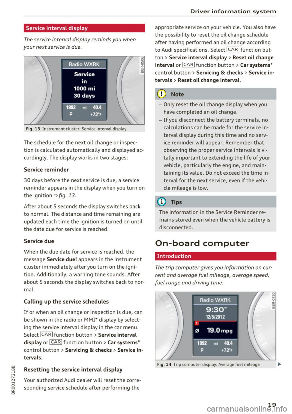
Fig. 13 Instrumel'lt cluster: Service interval display
8 .,, 0 ci:
"' ID
The schedule for the next oil change or inspec
tion is calculated automatically and displayed ac
cordingly. The display works in two stages :
Service reminder
30 days before the next service is due, a service
reminder appears in the display when you turn on
the ignition
¢ fig. 13.
After about 5 seconds the display switches back
to normal. The distance and time remaining are
updated each time the ignition is turned on until
the date due for service is reached.
Service due
When the due date for service is reached, the
message
Service due! appears in the instrument
cluster immediately after you turn on the igni
tion . Additionally, a warning tone sounds. After
about
5 seconds the display switches back to nor
mal.
Calling up the service schedules
If or when an oil change or inspection is due, can
be shown in the radio or MMI* display by select
ing the service interval display in the car menu.
Select
I CARI function button > Service interval
display
or I CAR I function button > Car systems*
control button > Servicing & checks > Service in
tervals .
Resetting the service interval display
Your authorized Audi dealer will reset the corre
sponding service schedule after performing the
Driver information system
appropriate service on your vehicle. You also have
the possibility to reset the oil change schedule after having performed an oil change according
to Audi specifications. Select
I CAR I function but
ton
> Service interval display> Reset oil change
interval
or ICARI function button > Car systems*
control button > Servicing & checks > Service in
tervals > Reset oil change interval.
(D Note
- Only reset the oil change display when you
have completed an oil change.
- If you disconnect the battery terminals, no
calculations can be made for the service in
terval display during this time and no serv
ice reminder will appear. Remember that
observing the proper service intervals is vi
tally important to extending the life of your
vehicle, particularly the engine, and main
taining its value. Do not exceed the time in
terval for the next service, even if the vehi cle mileage is low.
@ Tips
The information in the Service Reminder re
mains stored even when the vehicle battery is
disconnected.
On-board computer
Introduction
The trip computer gives you information on cur
rent and average fuel mileage, average speed ,
fuel range and driving time .
Fig. 14 Trip comp uter d isp lay: Average fuel mileage
19
Page 22 of 296
Driver information system
The following information is continuously evalu
ated by the trip computer and can be displayed
sequent ially in the instrument cluster display:
Fuel range
The estimat ed cruising range in miles (km) ap
pears in the disp lay. Thi s tells you how far your
vehicle wi ll be able to t ravel on the current tank
of fuel and with the same driving style. The dis
play changes in increments of 5 miles (10 km) .
Average fuel mileage
The average f uel economy in MPG (l/100 km)
since you last cleared the memory appears in this
display . You can use this display to adjust your
driving technique to achieve a desired mileage.
Current fuel mileage
The instantaneo us fue l cons umption in miles per
ga llon (l/100 km) is shown in this display. You
can use th is disp lay to adjust your driv ing techn i
que to achieve a desired mi leage.
Fuel consumption is recalculated at intervals of
33 ya rds (30 meters).
Average speed
The average speed in mph (km/h) since the last
time the display was reset appears in the disp lay.
Elapsed time
The length of time that you have been driving
since you last reset the memory appears in this
disp lay.
Distance
The distance that has been covered since the last
time the memory was cleared appears in the dis
play.
@ Tips
- Fuel consumptions (average and current),
range and speed are displayed in metric
units on Canadian models.
- All stored val ues w ill be lost if the vehicle
battery is disconnected.
20
Memories
The trip computer is equipped with two fully au
tomatic memories as well as an efficiency pro
gram*.
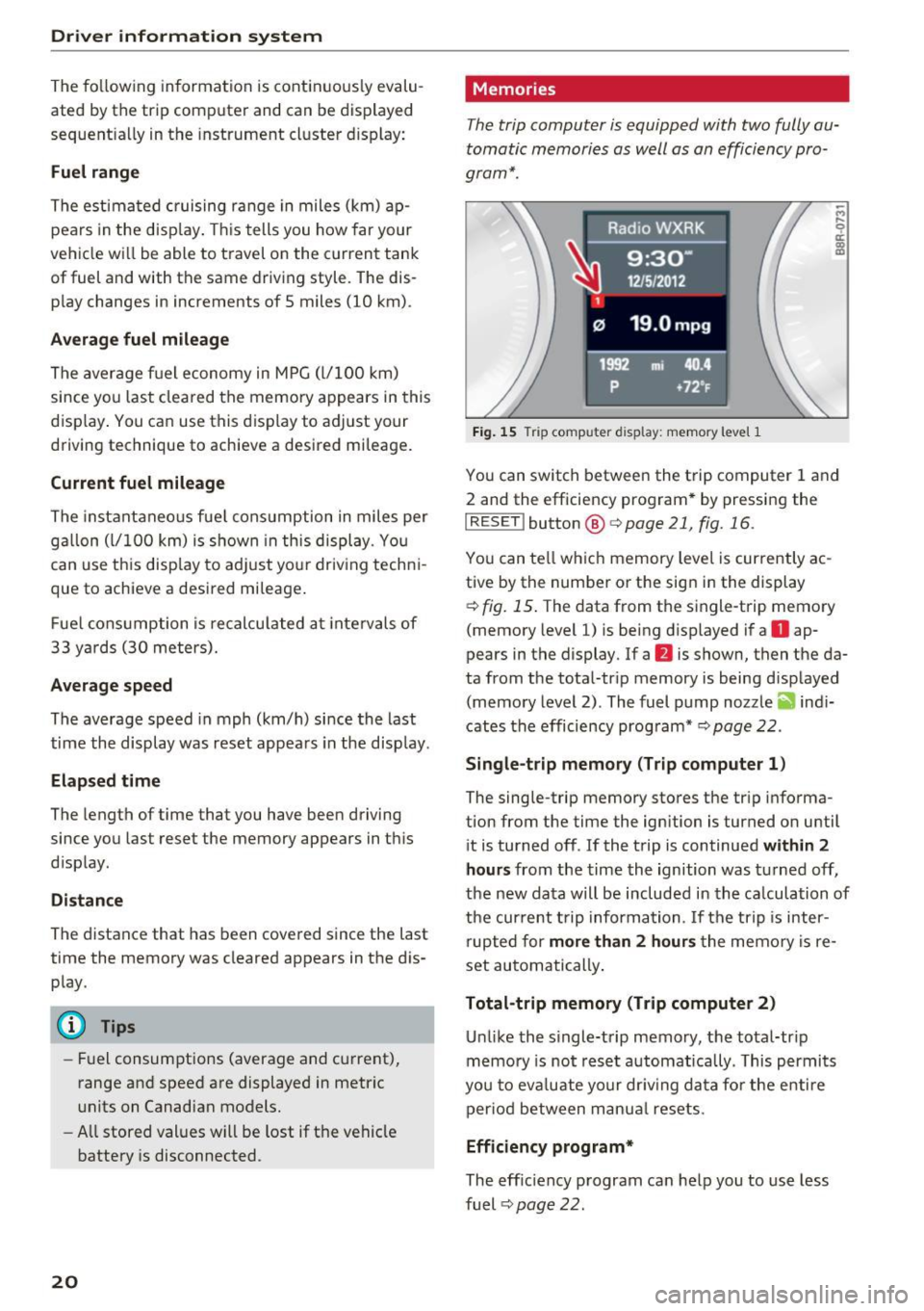
Fig. 15 Trip computer d isplay: memory level 1
You can switch between the trip computer 1 and
2 and the efficiency program * by pressing the
IRESET I button@<=>page 21, fig. 16 .
You can tell which memory level is currently ac
tive by the number or the sign in the display
c> fig. 15. The data from the single-trip memory
(memory level 1) is being d isplayed if a
D ap
pears in the display. If a
fJ is shown, then the da
ta from the total-trip memory is being d isplayed
(memory level 2). The fuel pump nozzle
ii1 indi
cates the efficiency program* <::;>
page 22.
Single-trip memory (Trip computer 1)
The single-trip memory stores the trip informa
tion from the time the ignition is turned on until
it is turned off . If the trip is continued
within 2
hours
from the time the ignition was turned off,
the new data will be included in the calculation of
the current trip information. If the trip is inter
rupted for
more than 2 hours the memo ry is re
set automatically .
Total-trip memory (Trip computer 2)
Unlike the single-trip memory, the total-tr ip
memory is not reset automatically . This permits
you to eva luate your dr iv ing data for the enti re
period between manua l resets.
Efficiency program*
The eff ic iency program can help you to use less
fuel <::;>
page 22.
Page 23 of 296
a,
a,
..... N l"N ..... 0 0
0:
co
Operation
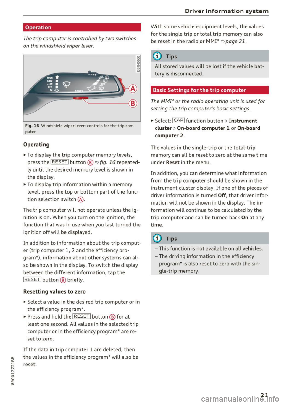
The trip computer is controlled by two switches
on the windshield wiper lever .
~------,@
Fig. 16 W indsh ield w iper lever: con tro ls for the tr ip com
p u ter
Operating
.,. To display the trip computer memory leve ls,
press the
I RESET ! button@ r:::> fig. 16 repeated
ly until the des ired memory level is show n in
the d isplay.
.,. To display trip informat ion within a memory
l evel, press the top or bottom par t of the func
t ion select io n switch
@ .
The trip computer w ill not operate un less the ig
ni tion is on. When you t urn on the ig nition, the
f u nction tha t was in use w hen you last turned the
i gnit io n off w ill be displayed.
In addition to information abo ut the trip compu t
e r (trip computer 1, 2 and the effic iency p ro
g ra m*), informat io n about othe r sy stems ca n al
so be shown in the disp lay. To switch the d isp lay
between the diff eren t informat io n, tap t he
I RESET I button @ briefly.
Resetting values to zero
.,. Se lect a v alue in the desired tr ip comp ute r o r i n
t h e effi ciency progra m* .
.,. Press and hold the
I RESET I button @ for at
l east one seco nd . All values in the selected tri p
computer or in the efficiency program* a re re
set to ze ro.
If th e d ata in tr ip compu ter 1 are deleted, t hen
the values in the efficiency p rogram* wi ll also be
reset .
Driver in forma tion system
W it h some vehicle eq uipment levels, the value s
f or the single trip or tota l trip memory can also
be reset in the radio or M MI *
r:::> page 21 .
(I_) Tips
All stored val ues will be lost if the vehicle bat
tery is disconnected.
Basic Settings for the trip computer
T he M MI* or the radi o operating unit is used for
setting the trip computer's basic settings .
.,. Sele ct: !CAR I function button> Instrument
cluster > On-board computer 1
or On-board
computer
2 .
The v alues in the si ng le- trip or the tot al-t rip
memo ry can all be reset to zero a t the same time
u nder
Re set in the men u.
In ad di tion, yo u ca n determine wha t in fo rm ation
fr om the trip compu ter should be s hown in the
in strument clu ster di splay. If one of the pieces of
drive r informa tion is tu rned
Off , that dr iver infor
mation will not be shown in the disp lay . The in
f o rmation w ill cont inue to be ca lculated by the
trip computer and can be turned back
On at any
t ime .
(D Tips
-Th is function is not available o n all vehicles.
- The driving info rmation in the efficiency
prog ram * is also reset to zero with t he s in
gle-trip memory.
21
Page 25 of 296
a,
a,
..... N l"N ..... 0 0
0:
co
On Board Diagnostic
System (OBD)
Malfunction Indicator lamp (MIL)
The Malfunction Indicator Lamp (MIL) ¢'4 in the
instrument cluster
¢ page 11, fig. 7 is part of the
On -Board Diagnostic (OBD II) system.
The warning/indicator light illuminates when the
ignition is switched on and goes out after the en
gine starts and the idle has stabilized . This indi
cates that the MIL is working properly .
If the light does not go out after the engine is
started, or illuminates while you are driving, a
malfunction may exist in the engine system .
If
the light illuminates, the catalytic converter
could be damaged.
Continue driving
with reduced power (avoiding
sustained high speeds and/or rapid accelera
tions) and have the condition corrected. Contact
your authori zed Audi dealer.
If the light illuminates, the electronic speed lim
iter may also be malfunctioning . For more infor
mation ¢
page 23, Electronic speed limiter.
An improperly closed fuel filler cap may also
cause the MIL light to illuminate (only vehicles
with gasoline engine)
¢page 212.
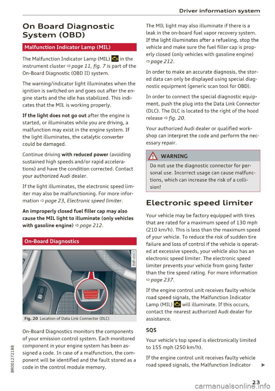
On-Board Diagnostics
Fig. 20 Locat ion of Data Link Connec tor (DLC )
On-Board Diagnostics monitors the components
of your emission control system. Each monitored
component in your engine system has been as
signed a code. In case of a malfunction, the com ponent will be identified and the fault stored as a
code in the control module memory.
Driver in forma tion system
The MIL light may also illum inate if there is a
leak in the on-board fuel vapor recovery system.
If the light illuminates after a refueling, stop the
vehicle and make sure the fuel filler cap is prop
erly closed (only vehicles with gasoline engine)
¢ page 212.
In order to make an accurate diagnosis, the stor
ed data can only be displayed using special diag
nostic equipment (generic scan tool for OBD).
In order to connect the special diagnostic equip
ment, push the plug into the Data Link Connector
(DLC). The DLC is located to the right of the hood
release ¢
fig. 20.
Your authorized Audi dea ler or qualified work
shop can interpret the code and perform the nec
essary repair.
A WARNING
-~
Do not use the diagnostic connector for per
sonal use. Incorrect usage can cause malfunc
tions, which can increase the risk of a colli
sion!
Electronic speed limiter
Your vehicle may be factory equipped with tires
that are rated for a maximum speed of 130 mph (210 km/h). This is less than the maximum speed
of your vehicle. To reduce the risk of sudden tire
failure and loss of control if the vehicle is operat
ed at excessive speeds, your vehicle also has an
electronic speed limiter. The electronic speed
limiter prevents your vehicle from going faster
than the tire speed rating . For more information
¢ page 237.
If the engine control unit receives faulty vehicle
road speed signa ls, the Malfunction Indicator
Lamp (MIL)
¢4 will illuminate. If this occurs,
contact the nearest authori zed Audi dealer for
assistance.
SQS
Your vehicle's top speed is electronically limited
to 155 mph (250 km/h).
If the engi ne control unit receives fa ulty vehicle
road speed signals, the Malfunction Indicator
lllJ,,
23