roof AUDI Q5 2017 Owners Manual
[x] Cancel search | Manufacturer: AUDI, Model Year: 2017, Model line: Q5, Model: AUDI Q5 2017Pages: 296, PDF Size: 74.43 MB
Page 4 of 296
Table of contents
About this Owner's Manual. . . . . .
5
Operation . . . . . . . . . . . . . . . . . . . . . . . . 6
Cockpit . . . . . . . . . . . . . . . . . . . . . . . . . . . 6
General illustration . . . . . . . . . . . . . . . . . . 6
Instruments and indicator lights 8
Instruments . . . . . . . . . . . . . . . . . . . . . . . . 8
Indicator lights . . . . . . . . . . . . . . . . . . . . .
11
Driver information system . . . . . . 17
Introduction . . . . . . . . . . . . . . . . . . . . . . . . 17
On-board computer . . . . . . . . . . . . . . . . . . 19
Efficiency program . . . . . . . . . . . . . . . . . . . 22
On Board Diagnostic System (OBD) . . . . .
23
Electronic speed limiter. . . . . . . . . . . . . . . 23
Auto Check Control . . . . . . . . . . . . . . . . . . 24
Opening and closing . . . . . . . . . . . . . 33
Keys . . . . . . . . . . . . . . . . . . . . . . . . . . . . . .
33
Central locking . . . . . . . . . . . . . . . . . . . . . . 35
Opening and closing rear lid . . . . . . . . . . . 40
Automatic rear lid/trunk lid operation
41
Emergency unlocking of the lu ggage
compartment lid . . . . . . . . . . . . . . . . . . . . 42
Child safety lock . . . . . . . . . . . . . . . . . . . . . 42
Power windows . . . . . . . . . . . . . . . . . . . . . 43
Panorama roof . . . . . . . . . . . . . . . . . . . . . . 44
Garage door opener (Home link) . . . . . . . . 45
Lights and Vision . . . . . . . . . . . . . . . . . 49
Exterior lighting . . . . . . . . . . . . . . . . . . . . . 49
Interior lighti ng . . . . . . . . . . . . . . . . . . . . .
52
V1s1on . . . . . . . . . . . . . . . . . . . . . . . . . . . . . 53
Windshield wipers . . . . . . . . . . . . . . . . . . . 54
Mirror . . . . . . . . . . . . . . . . . . . . . . . . . . . . . 56
Digital compass . . . . . . . . . . . . . . . . . . . . .
58
Seats and storage ...... ... .. .. .. .
General informa tion .......... .... .. .
Fr ont seats . .. .... ........... .. .. .. .
Memory function ... ................ .
60
60
61
62
Rear seat . . . . . . . . . . . . . . . . . . . . . . . . . . 63
Head restraints . . . . . . . . . . . . . . . . . . . . . 64
Center armrest . . . . . . . . . . . . . . . . . . . . . . 65
Luggage compartment . . . . . . . . . . . . . . . 66
Roof rack . . . . . . . . . . . . . . . . . . . . . . . . . . 69
Beverage holders . . . . . . . . . . . . . . . . . . . .
71
2
Climatized cupholders . . . . . . . . . . . . . . . . 72
(upholders in the door pockets . . . . . . . . 73
Ashtray . . . . . . . . . . . . . . . . . . . . . . . . . . . . 73
Cigarette lighter/socket . . . . . . . . . . . . . . 73
Storing . . . . . . . . . . . . . . . . . . . . . . . . . . . . 74
Warm and cold . . . . . . . . . . . . . . . . . . . 77
Climate control system . . . . . . . . . . . . . . . 77
Dr1v1ng ..... .. .. .. .. ............... 81
Steering . . . . . . . . . . . . . . . . . . . . . . . . . . . 81
Ign ition lock . . . . . . . . . . . . . . . . . . . . . . . . 81
Convenience key . . . . . . . . . . . . . . . . . . . . . 84
Driver messages . . . . . . . . . . . . . . . . . . . . .
85
Electromechanical parking brake . . . . . . . 86
Start/Stop system . . . . . . . . . . . . . . . . . . . 88
Speed warning system . . . . . . . . . . . . . . . .
91
Cruise control system . . . . . . . . . . . . . . . . 92
Automatic transmission 94
Hybrid
............................ 100
Hybrid drive . . . . . . . . . . . . . . . . . . . . . . . . 100
Audi adaptive cruise control and
braking guard . . . . . . . . . . . . . . . . . . . .
109
Introduction . . . . . . . . . . . . . . . . . . . . . . . . 109
Genera l information . . . . . . . . . . . . . . . . . 109
Audi adaptive cruise control . . . . . . . . . . . 111
Audi braking guard . . . . . . . . . . . . . . . . . . 115
Messages . . . . . . . . . . . . . . . . . . . . . . . . . . 116
Audi side assist . . . . . . . . . . . . . . . . . . 118
S ide assist . . . . . . . . . . . . . . . . . . . . . . . . . 118
Audi drive select . . . . . . . . . . . . . . . . . 122
Drive settings . . . . . . . . . . . . . . . . . . . . . . . 122
Parking aid . . . . . . . . . . . . . . . . . . . . . . . 125
Parking system plus with rearview camera
Adjusting the display and warning tones
Trailer hitch ...... ... .............. .
Error messages 125
130
130
130
Safety . . . . . . . . . . . . . . . . . . . . . . . . . . . . 131
Driving safety . . . . . . . . . . . . . . . . . . . . 131
Basics . . . . . . . . . . . . . . . . . . . . . . . . . . . . . 131
Correct passenger seating positions . . . . . 132
Pedal area . . . . . . . . . . . . . . . . . . . . . . . . . . 135
Page 46 of 296
Opening and clo sin g
Convenience opening/closing
The windows and the Panoramic sliding sunroof*
can be opened and closed with the mechanical
key or the emergency key.
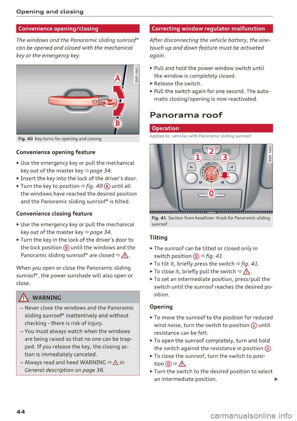
F ig . 40 Key turns for ope ning a nd clos ing
Con venienc e openin g fe ature
.,. Use the eme rgency key or pu ll the mechanical
key out of the master key ¢
page 34 .
! a,
.,. Insert the key into the lock of the driver's door .
.,. Turn the key to position¢
fig. 40 ® until all
the windows have reached the des ired position
and the Panoram ic sliding sunroof* is tilted.
Con venienc e clo sing f eatur e
.,. Use the emergency key or pull the mechanical
key out of the master key ¢
page 34.
.,. Turn the key in the lock of the driver's door to
the lock position @ until the w indows and the
Panoramic sliding sunroof* are closed¢,&. .
When you open or close the Panoramic sliding
sunroof*, the power sunshade will also open or
close.
A WARNING
- Never close the windows and the Panoramic sliding s unroof * inattentive ly and w ithout
check ing - there is risk of in jury .
- You must always watch when the w indows
are be ing raised so that no one can be trap
ped.
If you release the key, the closing ac
t ion is immediately cance led.
- Always read and heed WARNING
c> &. in
General description on page 36 .
44
Correcting window regulator malfunction
After disconnecting the vehicle battery, the one
touch up and down feature must be activated
agam .
.,. Pull and hold the power window switch until
the window is completely closed .
.,. Release the switch .
.,. Pull the sw itch agai n for one second. The auto
matic closing/open ing is now reactivated.
Panorama roof
Operation
App lies to: vehicles wit h Pano ramic sliding s unroof
Fig . 41 Sect ion from head liner: Knob for Pa noram ic s lid in g
su nroof
Tilting
.,. The sunroof can be tilted or closed only in
sw itch position @
c> fig. 41
.,. To t ilt it, briefly press the switch¢ fig. 41.
.,. To close it, briefly pull the switch¢,&. .
.,. To se t an intermed iate posi tion, p ress/pu ll the
sw itch un til the sunroof reaches the desired po
si tion.
Opening
.,. To move the sunroof to the position for red uced
w ind no ise, turn the switch to posit ion @ unt il
res istance can be felt.
.,. To open the sun roof complete ly, t urn and hold
the switch against the resistance in posit io n @ .
.,. To close the sunroof, turn the switch to posi
tion @¢,&. .
.,. Turn the switch to the desired position to select
an intermediate position. .,.
Page 47 of 296
Opening and closing th e sunshade
• To automat ica lly open the sunshade complete
l y, briefly press the switch@ in the desired ar
row direction .
• To stop the sunshade in an intermediate posi
tion, press the switch again, or
• Press and hold the switch in the desired arrow
direction.
• Release the switch when sunshade is at desired
pos it ion .
After the ign ition is switched off, you can still op
erate the Panoramic sliding sunroof for about 10
minutes . As soon as the driver's or passenger's
door is opened, the switch is inoperative.
The power sunshade can also be closed when the
Panoram ic sliding sunroof is open.
A WARNING
Pay careful attent ion when closing the Panor
am ic sliding sunroof -otherwise ser ious injury
could result! For this reason, always remove
the ignition key when leaving the vehicle.
@ Note
Always close your Panoramic sl iding sunroof
when leaving your vehicle . Sudden rain can
cause damage to the interior equipment of
your veh icle, particular ly the electronic equip
ment .
@ Tips
Information regarding convenience opening/
clos ing
~ page 44.
Emergency closing of the Panoramic sliding
sunroof
Applies to: veh icles with Panoramic sliding sunroof
If the Panoramic sliding sunroof detects an ob
ject in its path when it is closing, it will open
again automat ically. In this case, you can close
the roof with the power emergency closing func
tion .
a,
~ • Within five seconds after the sunroof opens au-
~ tomatically, pull the switch until the roof
8 closes . 0
0:
co
Openin g an d clos ing
Garage door opener
(Homelink)
Description
Applies to: vehicles with garage door opener (Home link)
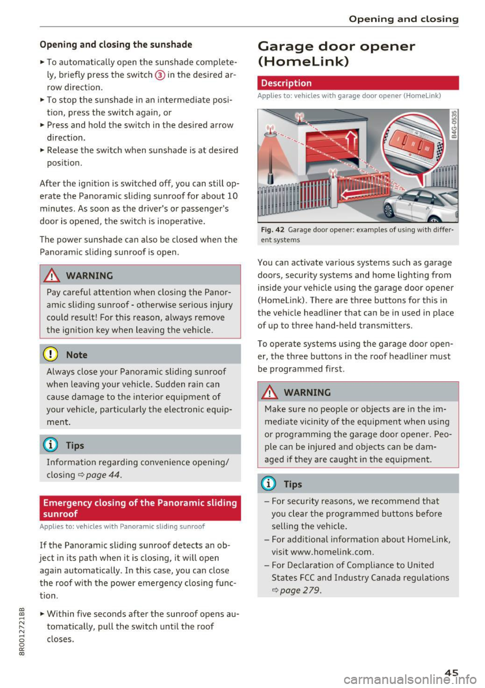
Fig. 42 Garage door opener: examples of using with differ
ent systems
You can activate various systems such as garage
doors, security systems and home lighting from
inside your vehicle using the garage door opener
(Homelink) . There are three buttons for th is in
the vehicle headliner that can be in used in place
of up to three hand-held transmitters .
To operate systems using the garage door open
er, the three buttons in the roof headliner must
be programmed first.
A WARNING
-
Make sure no peop le or objects are in the im-
mediate vicinity of the equipment when using
or p rogramm ing the ga rage door opener. Peo
p le can be injured and objects can be dam
aged if they are caught in the equipment.
(¼} Tips
- For security reasons, we recommend that
you clear the programmed buttons befo re
selling the vehicle .
- For add itiona l information about Homelink,
visit www.homelink.com.
- For Declaration of Compliance to United
States FCC and Indust ry Canada regulations
~page 279.
45
Page 48 of 296
Opening and clo sin g
Operation
Applies to: ve hicles w ith garage door opener (Homelink)
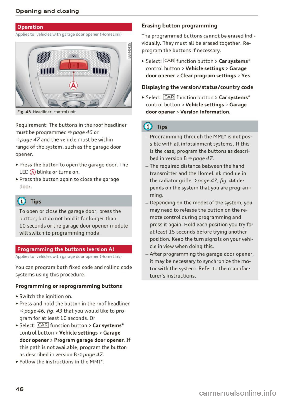
F ig. 43 Hea dlin er: co ntrol uni t
Requirement: The buttons in the roof headliner
must be programmed
Q page 46 or
¢
page 47 and the vehicle must be within
range of the system, such as the garage door
ope ner.
• Press the button to open the garage door . The
L E D @ blinks or turns on .
• Press the button again to close the garage
door .
@ Tips
To open o r close the garage door, press the
button, but do not hold it fo r lo nger than
10 seconds o r th e ga rage door opener module
w ill switch to prog ramming mode.
Programming the buttons (version A)
Applies to: ve hicles with ga rage doo r opener (Homeli nk}
You can program both fixed code and rolling code
systems using this procedure .
Programming or reprogramming buttons
• Switc h the ign ition on.
• Press and hold the but ton in the roo f headline r
¢
page 46, fig. 43 that you would like to pro
gram fo r at least 10 seconds. Or
• Se lect :
ICAR I function button> Car sys tems*
cont ro l button > Vehicle sett ing s > Garage
door opene r> Program garage door opener .
If
this path is not available, program the button
as descr ibed in version B ¢
page 47.
• Fo llow the inst ructions i n the MM I*.
46
Erasing button programm ing
The prog rammed but tons cannot be erased ind i
vidually . They must a ll be erased toge ther . Re
program the buttons if necessary.
• Sele ct:
I CAR I func tion b utton > Car sy ste m s*
con trol b utton > Vehicle setting s > Garage
door opener > Clear program setting s > Yes.
Displaying the version /status/country code
• Select: !CAR ! function button> Ca r sy stems *
control button > Vehicle setting s > Garage
door opener > Ver sion informa tion .
@ Tips
-Prog ramming through the MMI* i s not pos
sible wi th all infot ainm ent systems.
If th is
is the case, program the buttons as descri
bed in vers ion B ¢
page 47.
- T he required distance between the hand
transmitte r and the Homelink module in
the radiator grille ¢
page 47, fig. 44 de
pends on the system that you are program
ming.
- Depending on the mode l of the system, you
may need to release the b utton on the re
mote contro l dur ing programming and
press it again. Hold each position you try for
at least 15 seconds before trying another
posit ion . Keep the turn s ignals on your vehi
cle in view when doing this .
- After programm ing the garage door opener,
it may be necessary to synchron ize the mo
tor with the sys tem . Refer to the manufac
t u rer 's ins truct ions.
Page 49 of 296
a,
a,
..... N r-N ..... 0 0
0:
co
Programming the buttons (version B)
Appl ies to: ve hicles with garage door opener (Homelink)
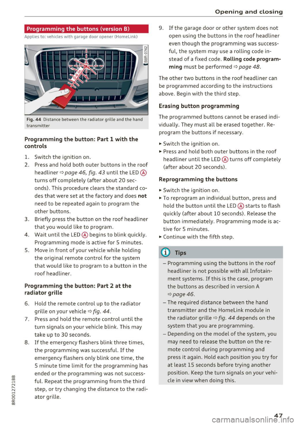
Fig . 44 D ist an ce betwee n the rad ia to r grill e and th e h and
tra nsmi tter
Programming the button: Part 1 with the
controls
1. Switch the ignition o n.
2 . Press and ho ld both outer buttons in the roof
headliner
c::> page 46, fig. 43 unti l the LED @
turns off completely (after about 20 sec
onds). T his procedure clears the standard co
des that were set at the factory and does
not
need to be repeated aga in to program the
other buttons .
3 . Briefly p ress t he b utton on the roof headline r
th at yo u wou ld like to prog ram.
4 . Wait un til the LED@ begi ns to blink quick ly .
Programm ing mode is ac tive for 5 minutes .
5 . Move in front of yo ur vehicle while holding
the orig inal remote contro l for the system
that would like to program to a button in the
roof headliner.
Programming the button : Part 2 at the
radiator gr ille
6 . Hold the remote control up to the radiator
grille on your vehicle¢
fig. 44.
7. Press and ho ld the remote control until t he
turn signals on yo ur vehicle bl ink . Th is may
tak e up to 30 seconds .
8 . If t he emergen cy f lashers blink th ree times,
the progr amming wa s suc cessful.
If t h e
emergency f las her s only blink one time, the
5 minute time limit for t he p rogramm ing has
ended o r the programm ing was not success
f ul. Repeat the programming from the third
step, o r try changing the distance to the radi
ator grille.
Open ing and closing
9 . If the garage door or o ther sys tem does not
open using the b uttons in the roof head liner
even tho ugh the programming was success
ful, the system may use a ro lling code in
stead of a fixed code.
Rolling code program
ming
must be perfo rmed c::> page 48.
The other two buttons in the roof hea dliner can
be programmed according to the inst ruct ions
above. Beg in with the third step.
Eras ing button prog ramming
T he programmed but tons can not be erased in di
vidually . They must a ll be erase d together . Re
program the buttons if necessary .
"' Switch th e ignit ion on.
"' Press and hold both ou ter but tons i n the roo f
headliner until the LED @turns off complete ly
(after about 20 seconds).
Reprogramming the buttons
"' Swit ch th e ignit ion on.
"' To reprogram an indivi dual but ton, p ress and
hold the button unti l the LED @starts to flash
quickly (afte r about 10 seconds) . Release the
button immediate ly. Prog ramming mode is ac
tive for 5 m inutes.
"' Continue w ith the fifth step.
@ Tips
- Prog ramming using the buttons in t he roof
head liner is not poss ible with a ll Infota in
ment systems . If this is the case, p rogram
t he b uttons as described in vers io n A
c::> page 46.
- T he required distance between t he hand
t ra nsmitte r and t he Homelink module in
t he radia tor grille ¢
fig. 44 depend s on th e
syste m th at y ou ar e pr og ra mming.
- De pending on the mo de l of t he syst em, you
m ay need to re lea se th e butt on o n the re
m ot e co ntrol dur ing progra mmin g an d
p ress it a gain. Hol d each position y ou try for
a t l east 15 seco nds befo re t rying a nother
p osit ion . Keep the turn s ignals on your veh i
cle in view whe n doin g this.
47
Page 50 of 296
Opening and closing
Rolling code programming
Applies to: vehicles w ith garage door opener (Homeli nk)
Rolling code programming is also needed for
some systems.
Identifying a rolling code
"' Press and hold the button in the roof headliner
that was already programmed .
"' Watch the LED @
c:> page 46, fig. 43. If the LED
blinks qu ickly, the systems (such as a garage
door) is equ ipped with a rolling code.
"' Program the rolling code as follows:
Activating the motor unit in a system
"'Locate the programming button on the sys-
tem's motor unit. The exact location and color
of the button may vary depending on the brand
of the system .
"'Pr ess the programm ing button on the ga rage
doo r opener motor unit (this w ill usually acti
vate an "indicator" on the motor unit). You now
have approximate ly
30 seconds to program the
button in the roof headliner.
Programming the button in the roof
headliner
"' Press and hold the previously programmed but
ton in the roof headliner for 2 seconds .
"' To end rolling code programming, press and
hold the button again for two seconds .
"' With some systems, the button may need to be
pressed a third time to end the programming
process .
After programming, the system should detect
the signal and begin mov ing when the button in
the roof headliner is pressed . Now you may pro
gram the other buttons as needed .
(D Tips
-The rolling code can be programmed more
quickly and more easily with the help of a
second person.
- If you have difficulty programming the roll
in g code, referring to the user guide for the
system may help .
48
Page 53 of 296
a,
a,
..... N l"N ..... 0 0
0:
co
Travel mode (Canada models)*
The headlight beam is asymmetrical. This pro
vides stronger illumination on the side of the
road on which you are driving. If you are driving
in a country that drives on the opposite side of
the road from your own country, this will cause
glare for oncoming drivers. To prevent glare:
- Travel mode must be selected in vehicles with
Xenon headlights*.
- In vehicles with halogen headlights, certain
areas of the headlight lenses must be covered
with waterproof adhesive covers that prevent
light from passing through. For more informa
tion, please see your authori zed Audi dealer or
authorized repair facility .
(!) Tips
When travel mode* is activated, a display in
the driver information system indicates this each time you switch the ignition on .
Adaptive light
Applies to: vehicles with adaptive light
When driving around bends, the relevan t area of
the rood is better illuminated .
Fig. 47 Adaptive lig ht when dr iving
Switching on adaptive light
.. Turn the light switch to AUTO c:> page 49,
fig. 45.
The adaptive light system is a combination of the
dynamic and the static cornering lights . With the
lights switched on, the dynamic cornering light
adapts to driving on curves . This is dependent
upon the vehicle speed and steering angle. This
provides better lighting through the curve. The
Lights and Vision
system operates in a speed range from approxi
mately 6 mph (10 km/h) to 68 mph (110 km/h).
The static cornering light switches on at speeds
of up to approximately 25 mph (40 km/h) when a
certain steering wheel angle is reached or when a
turn signal is activated. The area to the side of
the vehicle is illuminated better when turning.
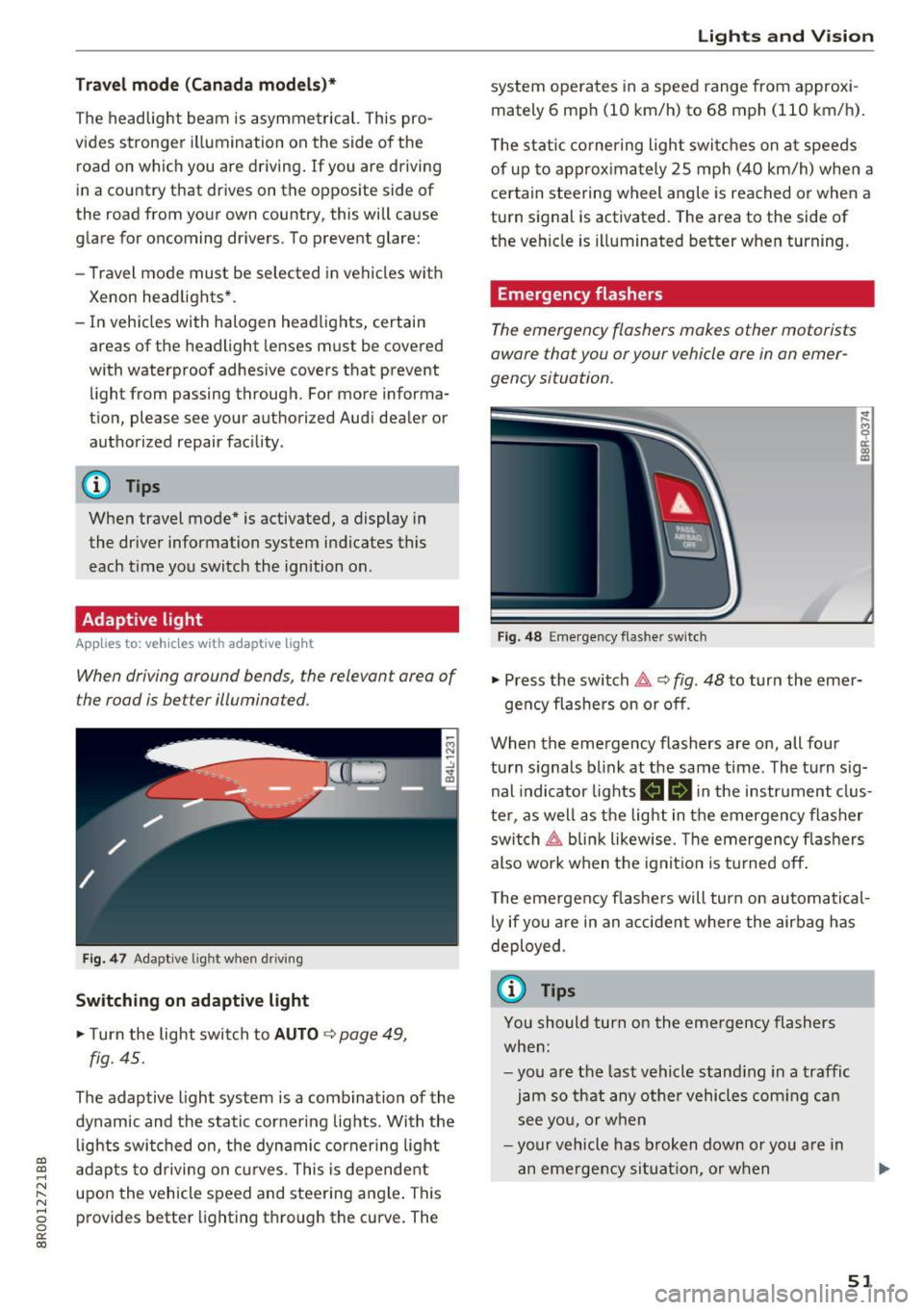
Emergency flashers
The emergency flashers makes other motorists
aware that you or your vehicle ore in on emer
gency situation.
Fig. 48 E mergency flas her switch
~
9 a: a, m
.. Press the switch &, c:> fig. 48 to turn the emer-
gency flashers on or off .
When the emergency flashers are on, all four
turn signals blink at the same time . The turn sig
nal indicator lights
B II in the instrument clus
ter , as well as the light in the emergency flasher
switch ~ blink likewise. The emergency flashers
also work when the ignition is turned off.
The emergency flashers will turn on automatical
ly if you are in an accident where the airbag has
deployed .
(0 Tips
You should turn on the emergency flashers
when:
-you are the last vehicle standing in a traffic
jam so that any other vehicles coming can
see you, or when
-your vehicle has broken down or you are in
an emergency situation, or when
51
Page 71 of 296
a,
a,
..... N r-N ..... 0 0
0:
co
Removing the cargo floor , installing
• To remove, lift t he cargo floor folded together
and pull it toward the rear lid .
• To install, place the folded cargo floor into
both retainers and unfold it.
Grab the protective tray on the ha ndles and pu ll
it out. You can also install a divider to divide @
the storage area. Depending on the vehicle
equipment level, the protective tray can have dif
ferent sizes and shapes .
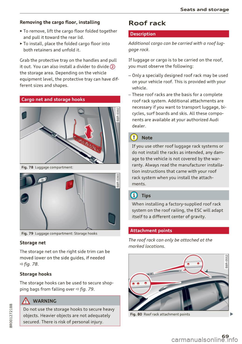
Cargo net and storage hooks
Fig. 78 Luggage compartment:
F ig . 79 Luggage compartment: Storage hooks
Storage net
The storage net on the right side trim can be
moved lower on the side guides, if needed
c:>fig. 78.
Storage hook s
The storage hooks can be used to secure shop
ping bags from falling over
c:> fig. 79.
A WARNING
Do not use the storage hooks to secure heavy
objects. Heavier objects are not adequately
secured. There is risk of pe rsonal injury.
Seats and storag e
Roof rack
Description
Additional cargo can be carried with a roof lug
gage rack .
If luggage or cargo is to be carried on the roof,
you must observe the following:
- On ly a specially designed roof rack may be used
on your vehicle roof. This is provided with your
veh icle .
- These roof racks are the basis for a complete
roof rack system . Additional attachments are
necessary if you want to transport luggage, bi
cycles, surf boards and skis. All these compo
nents are ava ilable at your a uthorized Aud i
dea le r.
(D Note
If you use other roof luggage rack systems or
do not install the racks as intended, any dam
age to the vehicle is not covered by the war
r anty. Always read the ma nufactu rer installa
tion ins tructions that came with yo ur roof
rack system when yo u install the atta ch
ments.
(D Tips
When ins tall ing a factory-supp lied roof rac k
system on the roof railing, the ESC will adapt
i tself to a differe nt center of gravity .
Attachment points
The roof rack can only be attached at the
marked locations .
Fig . 80 Roof rack attachment points
69
Page 72 of 296
Seats and storage
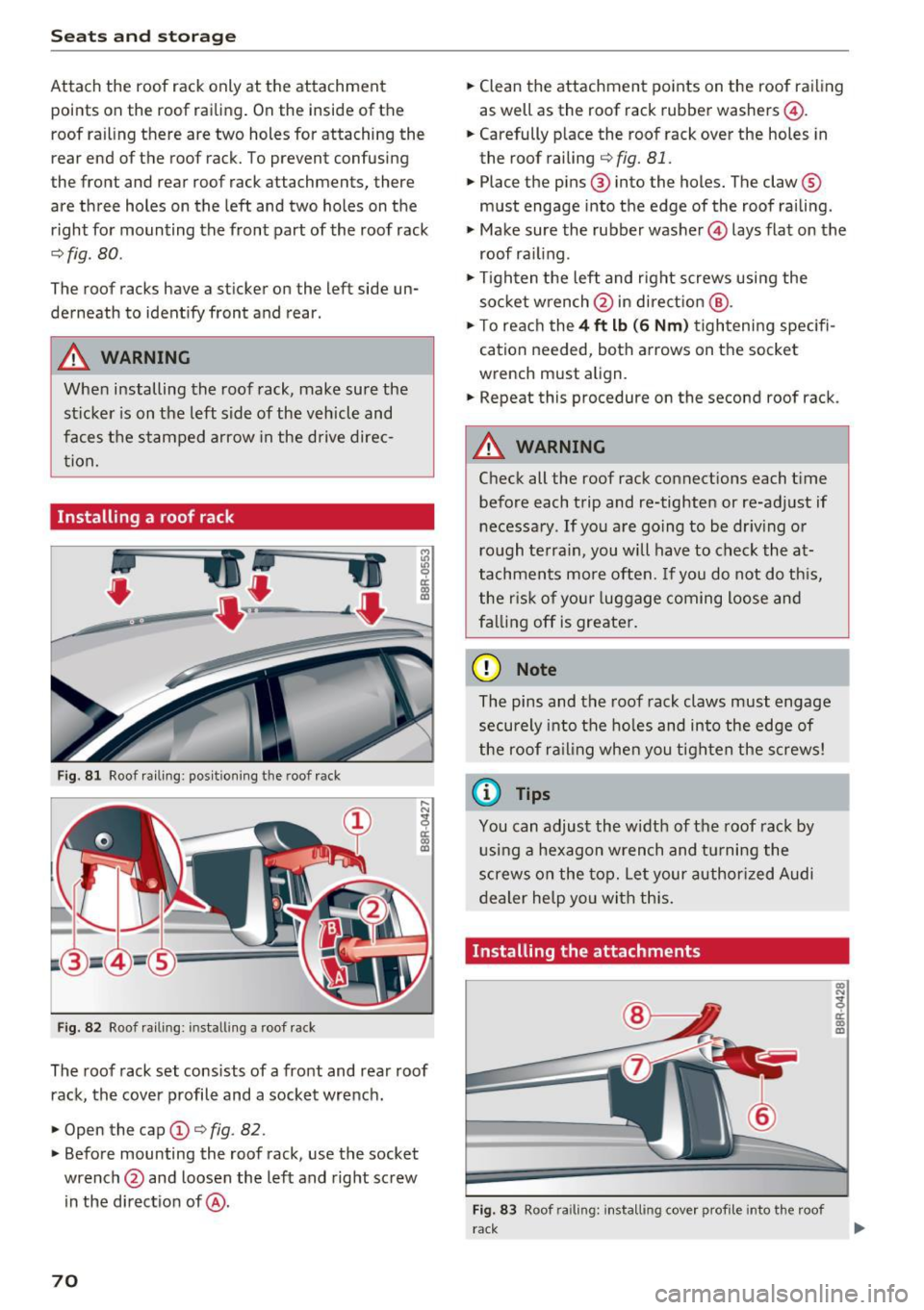
Attach the roof rack only at the attachment
points on the roof railing. On the inside of the
roof railing there are two holes for attaching the
rear end of the roof rack. To prevent confusing
the front and rear roof rack attachments, there
are three holes on the left and two holes on the
right for mounting the front part of the roof rack
~ fig . 80.
The roof racks have a sticker on the left side un
derneath to identify front and rear .
A WARNING
When installing the roof rack, make sure the
sticker is on the left side of the vehicle and
faces the stamped arrow in the drive direc
tion.
Installing a roof rack
Fig . 81 Roof ra iling : pos ition ing the roof rack
Fig . 82 Roof railing : installing a roof rack
The roof rack set consists of a front and rear roof
rack, the
cover profile and a socket wrench.
~ Open the cap (D c:> fig. 82.
~ Before mounting the roof rack, use the socket
wrench @and loosen the left and right screw
in the direction of@ .
70
~ Clean the attachment points on the roof railing
as well as the roof rack rubber washers@.
~ Carefully place the roof rack over the holes in
the roof railing
c:> fig. 81.
~ Place the pins@ into the holes. The claw®
must engage into the edge of the roof railing .
~ Make sure the rubber washer© lays flat on the
roof railing .
~ Tighten the left and right screws using the
socket wrench @ in direction @.
~ To reach the 4 ft lb (6 Nm) tightening specifi
cation needed, both arrows on the socket
wrench must align .
~ Repeat this procedure on the second roof rack.
A WARNING
Check all the roof rack connections each time
before each trip and re-tighten or re-adjust if
necessary .
If you are going to be driving or
rough terrain, you will have to check the at
tachments more often. If you do not do this,
the risk of your luggage coming loose and
falling off is greater.
(D Note
The pins and the roof rack claws must engage
securely into the holes and into the edge of
the roof railing when you tighten the screws!
(D Tips
You can adjust the width of the roof rack by
using a hexagon wrench and turning the
screws on the top. Let your authorized Audi
dealer help you with this.
Installing the attachments
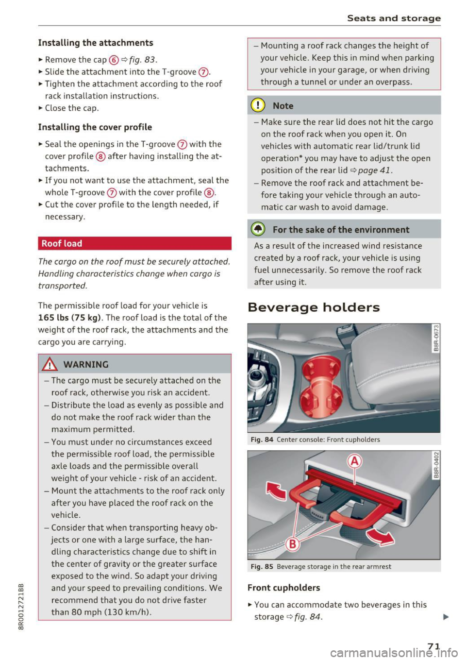
Fig. 83 Roof railing: installing cove r profile into the roof
rack
co
"' ~ er co a,
Page 73 of 296
a,
a,
..... r-1 ,-... r-1 ..... 0 0
0:
co
Installing the attachments
• Remove the ca p @ q fig . 83 .
• Slide the attachment into the T-groove 0-
• Tighten the attachment according to the roof
rack installation inst ructions .
• Close the cap.
Install ing the cov er profile
• Seal the openings in the T-groove 0 with the
cover profile @ after hav ing installing the at
tachments.
• If you not want to use th e attachment, seal the
whole T-groove
0 with the cover profile @.
• Cut t he cover profile to the length needed, if
necessary .
Roof load
The cargo on the roof mus t be securely attached.
Handling charac teristics change when cargo is
transported .
The permissible roof load for your veh icle is
165 lbs (75 kg ). The roof load is the total of the
weight of the roof rack, the attachme nts and the
cargo you are carrying .
_&, WARNING
- The cargo m ust be sec urely attached on the
roof rack, otherwise yo u risk a n accide nt.
- Dist ribute the load as evenly as possible and
do not make the roof rack wider than the
m ax imum permitted.
- Yo u must unde r no circumstances exceed
t he perm iss ible roof load, the permiss ible
ax le loads and the pe rm issib le overa ll
we ight of yo ur vehicle -risk of an accident.
- M ount the a ttachments to the roof rack only
after you have placed the roof rack on the
vehicle .
- C onsider that whe n transpo rting heavy ob
je cts or one wi th a large s urf ac e, the han
dling characterist ics c hange due to shift in
the cente r of gravity or the greater s urface
exposed to the w ind. So adapt your driving
and your speed to prevailing conditions. We
recommend that you do not dr ive faster
than 80 mp h (130 km/h) .
Seats and storag e
-Mounting a roof rack changes the height of
your veh icle. Keep t his in m ind when parking
your veh icle in your garage, or when dr iving
through a tunnel o r under a n overpass.
(D Note
- Ma ke sure the rea r lid does not hit the cargo
on the roof rack when you open it. On
vehicles with automatic rear lid/trunk lid
operation* you may have to adjust the open
position of the rear lid
~ page 41.
- Remove the roof rack and attachment be
fore taking your vehicle th rough an auto
matic car wash to avoid damage .
@ For the sake of the environment
As a result of the increased wind res istance
created by a roof rack, your vehicle is using
fuel u nnecessarily . So remove the roof rack
aft er using it.
Beverage holders
Fig . 84 Cente r conso le: Fro nt c upho lders
Fig. 85 Beverage storage in th e rea r arm rest
Front cupholders
• You ca n accommo date two beverages in this
storage
q fig . 84 .
71