wheel AUDI Q5 2017 Owners Manual
[x] Cancel search | Manufacturer: AUDI, Model Year: 2017, Model line: Q5, Model: AUDI Q5 2017Pages: 296, PDF Size: 74.43 MB
Page 5 of 296
CD
CD
.... N ,-... N ..... 0 0 C<'. 00
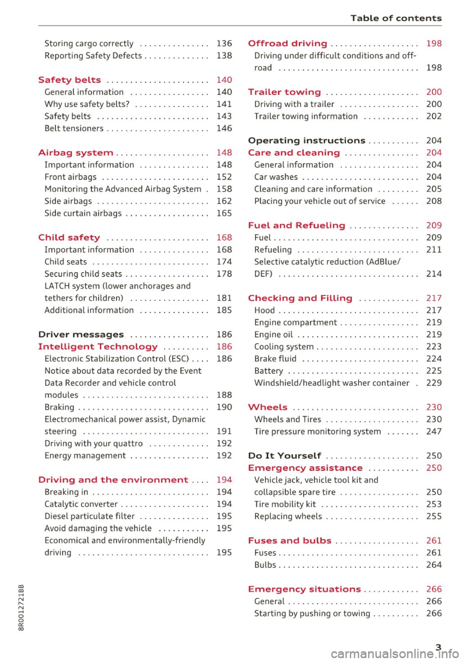
Storing cargo correctly . . . . . . . . . . . . . . . 136
R epo rting Safety Defects . . . . . . . . . . . . . . 138
Safety belts . . . . . . . . . . . . . . . . . . . . . . 14 0
General information . . . . . . . . . . . . . . . . . 140
Why use safety belts? . . . . . . . . . . . . . . . . 141
Safety belts . . . . . . . . . . . . . . . . . . . . . . . . 143
Belt tensioners . . . . . . . . . . . . . . . . . . . . . . 146
Airbag system . . . . . . . . . . . . . . . . . . . . 148
Important information . . . . . . . . . . . . . . . 148
Front airbags . . . . . . . . . . . . . . . . . . . . . . . 1S2
Monitoring the Advanced Airbag System . 158
Side airbags . . . . . . . . . . . . . . . . . . . . . . . . 162
Side curtain airbags . . . . . . . . . . . . . . . . . . 165
Child safety . . . . . . . . . . . . . . . . . . . . . . 168
Important information . . . . . . . . . . . . . . . 168
Ch ild seats . . . . . . . . . . . . . . . . . . . . . . . . . 174
S ecur ing ch ild seats . . . . . . . . . . . . . . . . . . 178
L ATCH system (lower anchorages and
tethers for chi ldren) . . . . . . . . . . . . . . . . . 181
Additional in fo rma tion
185
Driver messages . . . . . . . . . . . . . . . . . 186
Intelligent Technology . . . . . . . . . . 186
Elect ronic Stabilization Control (ESC) . . . . 186
Notice about data recorded by the Event
Data Recorder and vehicle control
modules . . . . . . . . . . . . . . . . . . . . . . . . . . . 188
B rak ing . . . . . . . . . . . . . . . . . . . . . . . . . . . . 190
E lect romechanical power assist, Dynamic
steering . . . . . . . . . . . . . . . . . . . . . . . . . . . 191
Dri ving with your quattro . . . . . . . . . . . . . 192
En erg y management . . . . . . . . . . . . . . . . . 192
Driving and the environment . . . . 194
Br eak ing in . . . . . . . . . . . . . . . . . . . . . . . . . 194
Catalytic converter . . . . . . . . . . . . . . . . . . . 194
Di ese l particulate filter . . . . . . . . . . . . . . . 195
Avoid damaging the vehicle . . . . . . . . . . . 195
Economical and environmentally-friendly
driving . . . . . . . . . . . . . . . . . . . . . . . . . . . . 195
Table of contents
Offroad driving . . . . . . . . . . . . . . . . . . .
198
Driving under difficult conditions and off-
ro ad . . . . . . . . . . . . . . . . . . . . . . . . . . . . . . 198
Trailer towing . . . . . . . . . . . . . . . . . . . . 200
Driving with a traile r . . . . . . . . . . . . . . . . . 200
Trailer towing information . . . . . . . . . . . . 202
Operating instructions . . . . . . . . . . . 204
Care and cleaning . . . . . . . . . . . . . . . . 204
Genera l information . . . . . . . . . . . . . . . . . 204
Car washes . . . . . . . . . . . . . . . . . . . . . . . . . 204
Cleaning and care information . . . . . . . . . 205
Plac ing your vehicle out of service . . . . . . 208
Fuel and Refueling . . . . . . . . . . . . . . . 209
Fuel .. .. .. .. .. .. .. ... .. ..... ... .. .. 209
Refueling ... .. .. .. .... .. ... .... .. .. 211
Selective catalytic reduct ion (Ad Blu e/
DEF) . . . . . . . . . . . . . . . . . . . . . . . . . . . . . . 214
Checking and Filling ........... .. 2 17
Hood ..... .. .. .. ................. .. 217
Eng ine compartm ent . . . . . . . . . . . . . . . . . 219
Eng ine oil . . . . . . . . . . . . . . . . . . . . . . . . . . 219
Cooling system . . . . . . . . . . . . . . . . . . . . . . 223
Brake fluid . . . . . . . . . . . . . . . . . . . . . . . . . 224
Battery . . . . . . . . . . . . . . . . . . . . . . . . . . . . 225
Windshield/headlight washer container
229
Wheels ........................... 230
Wheels and Tires . . . . . . . . . . . . . . . . . . . . 230
Tire pressure monitoring system 247
Do It Yourself . . . . . . . . . . . . . . . . . . . . 250
Emergency assistance . . . . . . . . . . . 250
Vehicle jack, vehicle tool kit and
collapsible spare tire . . . . . . . . . . . . . . . . . 250
T ire mobility kit . . . . . . . . . . . . . . . . . . . . . 253
Replacing wheels . . . . . . . . . . . . . . . . . . . . 255
Fuses and bulbs . . . . . . . . . . . . . . . . . . 261
Fuses . . . . . . . . . . . . . . . . . . . . . . . . . . . . . . 261
Bulbs . . . . . . . . . . . . . . . . . . . . . . . . . . . . . . 264
Emergency situations . . . . . . . . . . . . 266
General . . . . . . . . . . . . . . . . . . . . . . . . . . . . 266
Starting by pushing or tow ing . . . . . . . . . . 266
3
Page 9 of 296
CD
CD
.... N ,-... N ..... 0 0 C<'. 00
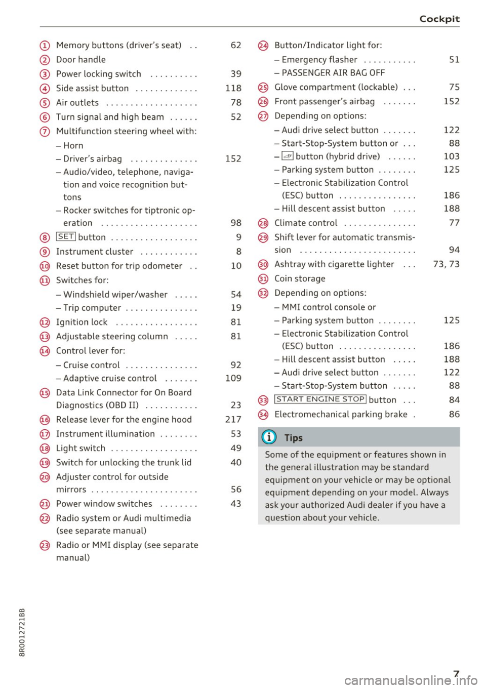
(!) Memory buttons (driver's seat)
@ Door handle
@ Power locking switch ......... .
© Side assist button ............ .
® Air outlets ..... ........ .... . .
@ Turn signal and high beam ... .. .
(j) Multifunction steering wheel with:
- Horn
- Driver's airbag ............ . .
- Audio/video, telephone, naviga-
tion and voice recognition but
tons
- Rocker switches for tiptronic op-
eration .. ............ ..... .
@ ISETI button ............... .. .
® Instrument cluster ........... .
@ Reset button for trip odometer
@ Switches for:
- Windshield wiper/washer
- Trip computer ............ .. .
@ Ignition lock ................ .
@ Adjustable steering column
@ Control lever for:
- Cruise control ............ .. .
- Adaptive cruise control ...... .
@ Data Link Connector for On Board
Diagnostics (OBD II) .......... .
@) Release lever for the engine hood
@ Instrument illumination ..... .. .
@ Light switch ............... .. .
@) Switch for unlocking the trunk lid
@ Adjuster control for outside
mirrors ..................... .
@ Power window switches ....... .
@ Radio system or Audi multimedia
(see separate manual)
@ Radio or MMI display (see separate
manual) 62
39
118
78
52
152
98
9
8
10
54
19
81
81
92
109
23
217
53
49
40
56
43
@ Button/Indicator light for:
- Emergency flasher .......... .
- PASSENGER AIR BAG OFF
@ Glove compartment (lockable) ...
@ Front passenger's airbag
@ Depending on options:
- Audi drive select button ...... .
- Start-Stop-System button or .. .
- Id'! button (hybrid drive) ..... .
- Parking system button ....... .
- Elect ronic Stabilization Control
(ESC) button . .............. .
- Hill descent assist button .... .
@ Climate control .. ............ .
@ Shift lever for automatic transmis-
sion ....... .. .............. .
@ Ashtray with cigarette lighter
@ Coin storage
@ Depending on options:
- MMI control console or
- Parking system button ....... .
- E lectronic Stabilization Control
(ESC) button . .. ............ .
Cockpit
51
75
152
122
88
103
125
186
188
77
94
73, 73
125
186
- Hill descent assist button . . . . . 188
-Audi drive select button . . . . . . . 122
- Start-Stop-System button . . . . . 88
@ I START ENGINE STOP! button . . . 84
@> Electromechanical parking brake 86
(D Tips
Some of the equipment or features shown in
the general illustration may be standard
equipment on your vehicle or may be optional
equipment depending on your model. Always
ask your authorized Audi dealer if you have a
question about your vehicle.
7
Page 53 of 296
a,
a,
..... N l"N ..... 0 0
0:
co
Travel mode (Canada models)*
The headlight beam is asymmetrical. This pro
vides stronger illumination on the side of the
road on which you are driving. If you are driving
in a country that drives on the opposite side of
the road from your own country, this will cause
glare for oncoming drivers. To prevent glare:
- Travel mode must be selected in vehicles with
Xenon headlights*.
- In vehicles with halogen headlights, certain
areas of the headlight lenses must be covered
with waterproof adhesive covers that prevent
light from passing through. For more informa
tion, please see your authori zed Audi dealer or
authorized repair facility .
(!) Tips
When travel mode* is activated, a display in
the driver information system indicates this each time you switch the ignition on .
Adaptive light
Applies to: vehicles with adaptive light
When driving around bends, the relevan t area of
the rood is better illuminated .
Fig. 47 Adaptive lig ht when dr iving
Switching on adaptive light
.. Turn the light switch to AUTO c:> page 49,
fig. 45.
The adaptive light system is a combination of the
dynamic and the static cornering lights . With the
lights switched on, the dynamic cornering light
adapts to driving on curves . This is dependent
upon the vehicle speed and steering angle. This
provides better lighting through the curve. The
Lights and Vision
system operates in a speed range from approxi
mately 6 mph (10 km/h) to 68 mph (110 km/h).
The static cornering light switches on at speeds
of up to approximately 25 mph (40 km/h) when a
certain steering wheel angle is reached or when a
turn signal is activated. The area to the side of
the vehicle is illuminated better when turning.
Emergency flashers
The emergency flashers makes other motorists
aware that you or your vehicle ore in on emer
gency situation.
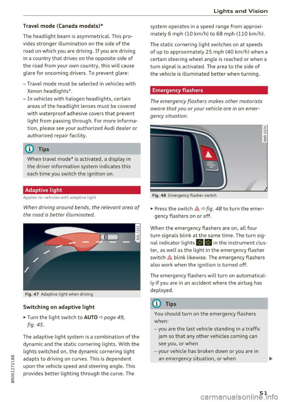
Fig. 48 E mergency flas her switch
~
9 a: a, m
.. Press the switch &, c:> fig. 48 to turn the emer-
gency flashers on or off .
When the emergency flashers are on, all four
turn signals blink at the same time . The turn sig
nal indicator lights
B II in the instrument clus
ter , as well as the light in the emergency flasher
switch ~ blink likewise. The emergency flashers
also work when the ignition is turned off.
The emergency flashers will turn on automatical
ly if you are in an accident where the airbag has
deployed .
(0 Tips
You should turn on the emergency flashers
when:
-you are the last vehicle standing in a traffic
jam so that any other vehicles coming can
see you, or when
-your vehicle has broken down or you are in
an emergency situation, or when
51
Page 54 of 296
Lights and Vision
-yo ur vehicle is being towed by a tow truck or
if you are towing another vehicle behind
you.
Turn signal and high beam lever
The lever on the le~ side of the steering column
is us ed to operat e the turn signals and th e high
beam as well as the headlight flasher.
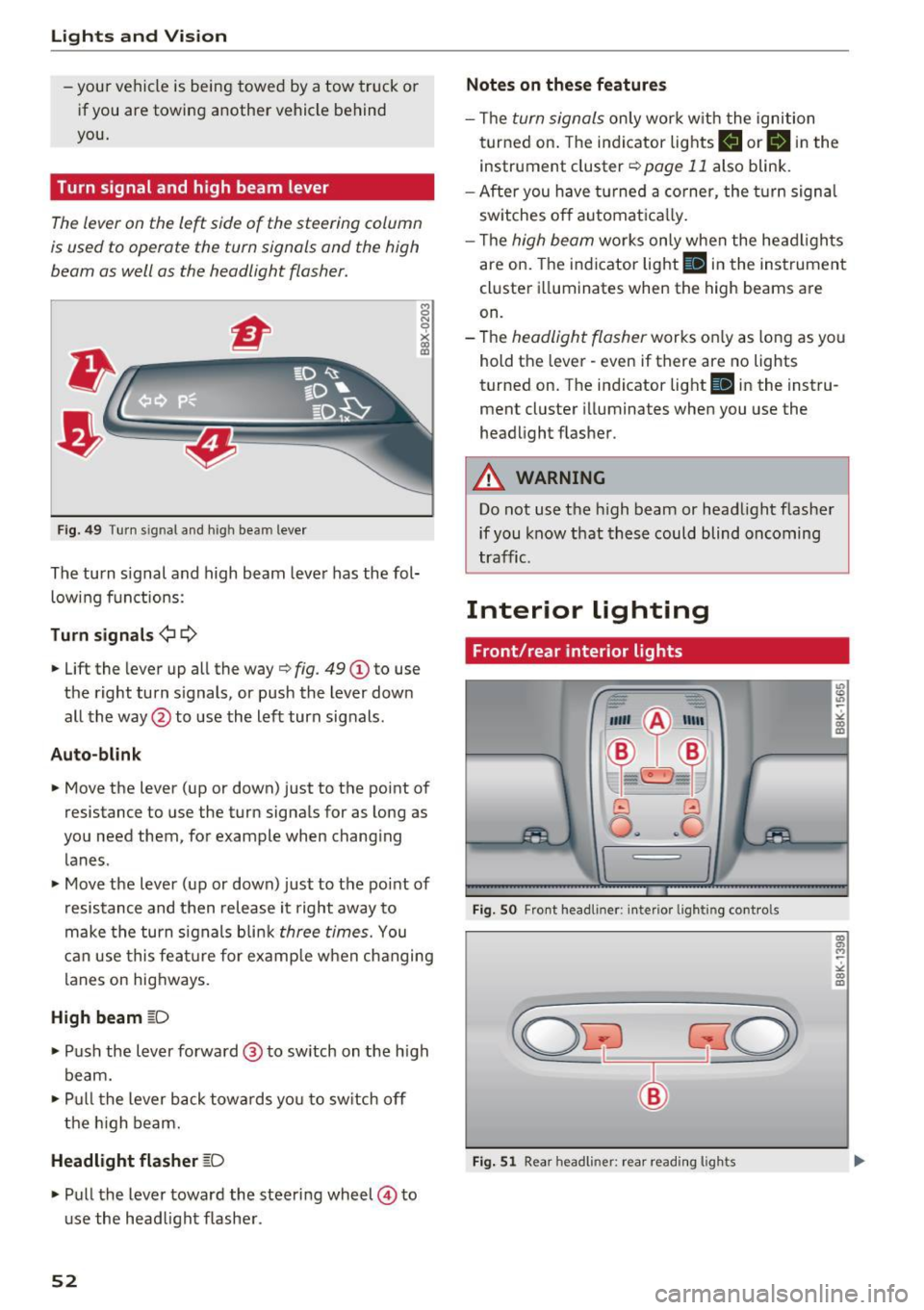
F ig . 4 9 Tu rn s ig na l a n d h ig h beam leve r
The turn signal and high beam leve r has the fol
low ing f unctions :
Turn signals ¢¢
8 N 'i'
~ (0
• Lift the lever up al l the way c> fig . 49 (D to use
the right turn s ignals, or push the lever down
all the way@to use the left turn signals .
Auto-blink
• Move the lever (up or down) just to t he point of
resistance to use the turn signals for as long as
yo u need them, for example when chang ing
lanes .
• Move the lever (up or down) just to the point of
resistance and then release it right away to
make the turn signals b li nk
three times. You
can use this fea ture for example when ch anging
lanes on hig hways.
High beam ~D
• Push the l ever forward @ to sw itch on the h igh
beam.
• Pull t he lever back towa rds you to sw itch off
t he hig h beam.
Headlight flasher ~D
• Pu ll the lever toward the steering wheel © to
u se the head light f lashe r.
52
Notes on these features
- Th e turn signals on ly work w it h the ignition
t urned on. The indi cator lights
B or B in the
instrument cluster¢
page 11 also blink .
- After you have turned a co rner, the turn signa l
sw itches o ff automat ica lly.
- Th e
high beam works only when the head ligh ts
are on. The indicator light
Bl in the instrumen t
cl uster illuminates when the high beams are
on.
- The
headlight flasher works o nly as long as yo u
hold t he lever - even if there are no lights
turned on. T he indicator light
Bl in the inst ru
ment cluster illuminates when you use the
headlight flas her .
A WARNING
Do not use the h igh beam or head light flasher
if you know that these could blind oncoming
tra ffic.
Interior lighting
Front/rear interior lights
Fig. SO Fro nt headl iner: interio r li gh tin g cont ro ls
Fig. 51 Rear h eadli ner: rea r read ing ligh ts
" co (0
co a, M ~
"' co (0
Page 62 of 296
Seat s and sto rage
Seats and storage
General information
Why is your seat adjustment so important?
The safety belts and the airbag system can only
provide maximum protection if the front seats are correctly adjusted .
There are various ways of adjusting the front
seats to provide safe and comfortable support
for the dr iver and the front passenger . Adjust
your seat properly so that:
- you can easily and quickly reach all the switches
and controls in the instrument panel
- your body is properly supported thus reducing
physical stress and fatigue
- the safety belts and a irbag system can offer
maximum protection ¢
page 148.
In the following sections, you will see exact ly
how you can best adjust your seats.
There are spec ial regulat ions and instr uctions for
installing a c hild safety seat on the front pas
senger 's seat . Always fo llow the information re
garding child safety provided in ¢
page 168,
Child safety.
A WARNING
Incorrect seating position of the driver and all
other passengers can result in serious person
al injury.
- Always keep your feet on the floor when the
vehicle is in motion - never put your feet on
top o f the instrument pane l, o ut of the win
dow o r on top of the sea t cushion. This ap
plies espe cially to the passenge rs.
If your
seat ing pos ition is inco rre ct, you increase
the risk of injury in the case of sudden b rak
ing or an accident . If the airbag inf lates and
the seating position is incor rect, this could
result in personal injury or even death.
- It is important for both the driver and front
passenge r to keep a d istance o f at least
10 inches (25 cm) between themselves and
the steering wheel and/or instrument pan el. If you're s itting any closer than this, the
airbag system cannot pro tect you properly.
60
In addition, the front seats and head re
straints must be adjusted to your body
he ight so that they can give you maximum
protection .
- Always try to keep as much distance as pos
sible between yourself and the steer ing
wheel or instrument panel.
- Do not adjust the driver's or front passeng
er's seat while the veh icle is moving. Yo ur
seat may move unexpectedly, causing sud
den loss of vehicle contro l and personal in
jury. If you ad just yo ur seat while the veh icle
is moving, you a re o ut of pos ition.
, Driver's seat
The correct seat position is important for safe
and relaxed driving .
We recommend that you adjust the dr iver's seat
i n the following manner:
.. Adjust the seat in fore and aft direction so that
you can easi ly push the pedals to the floor
while keep ing your knees slightly bent¢
A. in
Why is your seat adjustment so important? on
page 60 .
.. Adjust the seatback so that when yo u sit with
your back agains t the seatback, you can still
gras p the top of the steering wheel.
.. Adjust the head res traint so the uppe r edge is
as even as possib le w ith the top of you r head. If
that is not possible, try to adjust the head re
straint so that it is as close to this pos it ion as
possible ¢
page 64.
A WARNING
Neve r place any objects in the dr iver's foo t
well. An object could get into the pedal area and inte rfere with pedal function. In case of
sud den bra king or an ac cident, you w ould no t
be ab le to b rake o r accelerate.
-
Page 81 of 296
![AUDI Q5 2017 Owners Manual CD
CD
.... N ,-... N .... 0 0 C<. 00
[i] Adjusting seat heating*
Pressing the button switches the seat heating on
at the highest setting (level 3) . The LEDs indicate
the temperat AUDI Q5 2017 Owners Manual CD
CD
.... N ,-... N .... 0 0 C<. 00
[i] Adjusting seat heating*
Pressing the button switches the seat heating on
at the highest setting (level 3) . The LEDs indicate
the temperat](/img/6/57633/w960_57633-80.png)
CD
CD
.... N ,-... N .... 0 0 C<'. 00
[i] Adjusting seat heating*
Pressing the button switches the seat heating on
at the highest setting (level 3) . The LEDs indicate
the temperature level. To reduce the tempera
ture, press the button again. To switch the seat heating off, press the button repeatedly until the
LED turns off.
After 10 minutes, the seat heating automatically
switches from level 3 to level 2.
lil Adjusting seat ventilation*
Pressing the button switches the seat ventilation
on at the highest sett ing (level 3). The LEDs indi
cate the venti lation level. To reduce the ventila
tion level, press the button again. To switch the
seat v entilation off, press the button repeatedly
until the LED turns off.
I ..., FRONT I Switch the defroster on/off
The windshield and side windows are defrosted
or cleared of condensation as quickly as possib le.
The maximum amount of air flows mainly from
the vents below the windshield. Recirculation
mode switches off. The temperature should be
set to 72 °F (22 °() or higher. The temperature is
controlled automatically .
T he
IAUTOI button switches the defroster off.
llliil REARI Switching rear window heater on/
off
The rear window heater on ly operates when the
engine is running. It switches off automatica lly
after a few minutes, depending on the outs ide
temperature.
To prevent the rear window heater from switching off automatically, press and hold the
!llil> REAR I
button for more than 2 seconds . This remains
s tored until the ignition is switched off .
Air vents
You can open and close the center and rear air
vents using the thumbwheels . The levers adjust
the direction of the airflow from the vents.
You can adjust the air temperature in the rear by
turning the thumbwheel toward the red side to
Warm and cold
make it warmer or toward the blue s ide to make
it coo ler.
A WARNING
-~
- Do not use the recirculation for extended
periods of time. The windows could fog up
since no fresh air can enter the vehicle . If
the windows fog up, press the air rec ircula
tion button again immed iately to switch off
the air rec irculat ion function or select de
frost.
- Individuals with reduced sensit ivity to pain
or temperature could develop burns when
using the seat heating* function. To reduce
the risk of injury, these individua ls should
not use seat heating.
(D Note
To avoid damage to the heating elements* in
the seats, do not kneel on the seats or place heavy loads on a small area of the seat.
Setup
The basic climate control settings can be adjust
ed in the radio or MMI*.
"'Select: !CAR I function button> A/C control but
ton. Or
"' Select:
!CAR ! function button> Car systems*
control button >
A/C.
Automatic recirculation
When switched on, automat ic rec irculat ion con
trols the recirculation mode automatically. If the
windows fog up, press the
I@ F RON T I button.
Synchronization
When synchronization is switched on, the same
settings are appl ied to both the driver and front
passenger , except for the seat heating/ventila
t ion* . Synchronization switches off when you ad
just the settings on the front passenger's sid e.
You can also sw itch synchronizat ion on by press-
i ng and holding the knob on the driver's side. ..,.
79
Page 83 of 296
a,
a,
,...,
N l"N ,...,
0 0
0:
co
Driving
Steering
Manually adjustable steering wheel
The height and reach of the steering wheel can
be adjusted .
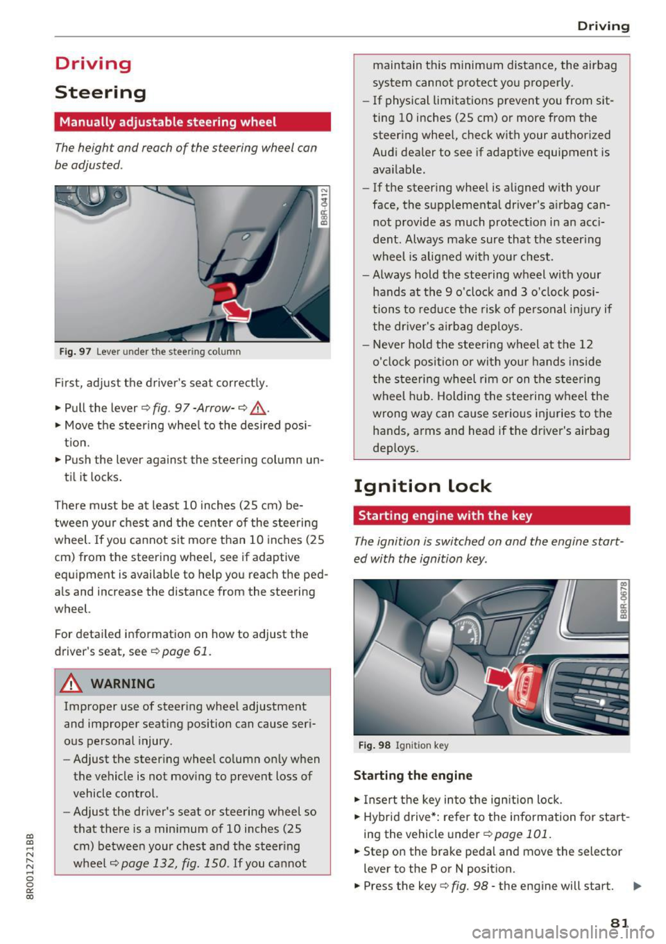
Fig. 97 Lever under the steering column
Fi rst, ad just t he driver 's sea t correct ly.
• Pull the lever ¢
fig. 97 -Arrow- ¢ A.
• Move the steer ing whee l to the desired posi
t ion.
• Push the lever against the steeri ng column un-
ti l it locks .
There must be at leas t 10 inches (25 cm) be
tween your chest and the center of the stee rin g
wheel. If yo u cannot sit mo re than 10 inches (25
cm) from the steering wheel, see if adaptive
equipment is available to help you reach the ped
a ls and increase the distance from the steering
wheel.
F or detailed information on how to adjust the
driver's seat, see
¢ page 61 .
.&_ WARNING
Improper use of steering wheel adjustment
and improper seating position can cause ser i
ous personal injury.
- Adjust the steering whee l co lumn on ly w hen
the vehicle is not mov ing to prevent loss of
vehicle control.
- Adjust the driver's seat or steering wheel so
that there is a min imum of 10 inches (25
cm) betwee n your chest and t he steer ing
w heel
¢page 132, fig. 150 . If you cannot
-
D rivi ng
maintain t his minim um distance, the airbag
system cannot p rotect yo u proper ly.
- If physical limitations prevent you from sit
ting 10 inches (25 cm) or more from the
steer ing whee l, check with your author ized
Audi dealer to see if adaptive equipment is
ava ilable.
- If the steer ing whee l is aligned w ith your
face, the supplementa l driver's a irbag can
not provide as much protect io n in an acc i
dent. Always ma ke sure that the steer ing
wheel is aligned with you r chest.
- Always hold the steering wheel with your
hands at the 9 o'clock and 3 o' clock posi
tions to reduce the risk of pe rso nal inju ry if
the dr iver's a irbag dep loys .
- Never ho ld the stee ring wheel at the 12
o'cl ock position or wi th you r hands inside
the stee rin g wheel rim or on t he s teer ing
wheel h ub. Holding the stee ring w heel the
wrong way can cause serious inj uries to the
hands, arms and head if the driver's airbag
deploys .
Ignition lock
Starting engine with the key
Th e ignition is switched on and the engine start
ed with the ignition key .
Fig . 9 8 Igh iti oh key
Starting the engine
• Insert the key into the ign ition lock .
• Hybrid drive*: re fer to the information for start
ing the vehicle under
¢ page 101.
• Step on the brake pedal an d move the selector
lever to the P or N position.
• Press the key¢
fig. 98 -the engine will start. II>
81
Page 89 of 296
CD
CD
.... N ,-... N .... 0 0 C<'. 00
Emergency brake function
An emergency brake ensures tha t the vehicle can
be slowed down even if the
normal brakes fai l
¢ page 88, Emergency braking.
A WARNING
If a drive range is engaged with t he vehicle
stat iona ry and the engine running, you must
in no instance accelerate care lessly . Other
w ise the vehicle will start to move immed iate
ly- risk of a n accide nt.
(D Tips
- If the parking brake is app lied with the igni
tion switched off, the indicator lights in the
switch and . (USA models)/ . (Cana-
da models) in the instrumen t cluster will go
out af ter a ce rtain per io d of t ime .
- Occasiona l noises when the park ing brake is
applied and re leased a re normal and a re not
a cause for conce rn.
- When the vehicle is parked, the park ing
brake goes th ro u gh a se lf-tes t cycle at regu
l a r i nte rva ls . Any associated noises a re no r
mal.
Parking
~ P ress the brake ped al to stop the vehicle.
~ Pull the switch c::> page 86, fig. 102 to set the
parking b rake.
~ Move the selecto r lever to P .
~ Turn the eng ine off c::> .&, .
-
~ When on incl ines or declines, turn the steering
wheel so that the veh icle w ill roll into the curb
if it beg ins to move .
A WARNING
-Whe n you leave your ve hicl e -even if onl y
br iefly- alw ays remove the ig nition key. Thi s
applies p articul arly when children rem ain i n
t h e ve hicle . Othe rwise the c hildren could
sta rt the eng ine, release t he parking brake
o r operate elect rical eq uipment (e.g. powe r
windows). There is the risk of an accident.
- When the vehicle is loc ke d , no one - part icu
larly not children shou ld remain in the vehi-
-
D riving
cle. Locked doors make it more d ifficult for
emergency wo rkers to get into the vehicle -
putting lives at r isk.
Starting from rest
The starting assist function ensures that the
parking brake is released automatically upon starting.
Stopping and applying parking brake
~ Pull the sw itch to app ly the parkin g brake.
Starting and automatically releasing the
parking brake
~ W he n you start to drive as usu a l, t he p ark ing
b rake is automa tic ally released and yo ur vehicle
beg ins to move.
When stop ping at a tr affic sig nal or sto pping in
c ity traff ic on vehicles wi th an aut omat ic t ra ns
mission, t he parking brake can be app lied . The
vehicle does not have to be held with the foot
bra ke. The pa rking brake e liminates the tendency
to c reep w ith a dr ive range engaged. As soon as
you drive off as usual, the parking brake is re leased a utomat ica lly and the vehicle starts to
move .
Starting on slopes
When starting on incl ines, the sta rting assist pre
vents the vehicle from un intent iona lly rolling
back. The b raking force of the parking brake is
not re leased unt il su ff icient dr iving force has
been buil t up at t he wheels .
(D Tips
For safety reasons, the park ing brake is re
l eased automatically on ly when t he d river's
safety be lt is engaged in t he buc kle.
Starting off with a trailer
To prevent rolling back unintentionally on an in
cline, do the following:
~ Keep the switch pulled and depress the acceler
ator . The parking brake stays applied and pre-
vents the veh icle from roll ing backward . .,,.
87
Page 90 of 296
Driving
"'You can re lease the switch once you are sure
that you are developing enough driving force at
the wheels by depressing the accelerator.
Depending on the weight of the r ig (vehi cle and
trai ler) and t he severity of the incline, you may
ro ll backwards as you start . You ca n prevent roll
ing bac kwards by holding the parking brake
sw itch pulled out and accelerating -just as you
wou ld when sta rting on a hill with a conventional
hand b rake.
Emergency braking
In the even t that the conventional brake system
fails or locks .
"'In an emergency, pull the switch and cont inue
to pull it to slow your ve hicle down with the
park ing b rake .
"' As soon as you release the switch or accelerate,
the b raking process stops .
If you pull the sw itch and hold it above a speed of
about 5 mph (8 km/h), the eme rge ncy brak ing
f u nction is ini tiated . The vehicle is braked at all
four whee ls by activating th e hydrau lic brake sys
t em. T he b rake perfo rman ce is sim ila r to making
a n emergency stop ~.&, .
In order not to activate the emergency brak ing by
mista ke, an audib le wa rn ing tone (buzz er)
sounds w hen the sw itch is p ulled . As soon as the
sw itch is rele ased, or the a cce le ra to r pedal is de
p ressed, eme rgency bra king stops.
_& WARNING
Emergency braking should only be use d in an
emergency, w hen the normal foot brake has
failed or the bra ke peda l is obstr ucted . Using
the parking b rake to perfo rm emergency
brak ing will slow your vehicle down as if you
had made a fu ll bra ke ap plication . The laws of
physics c annot be suspended even wi th E SC
a nd i ts asso ciated componen ts (AB S, AS R,
ED S). I n corne rs and when r oad or we ather
c ondi tions are bad , a f ull bra ke ap plicat ion
can ca use the vehicle to sk id or the rea r end to
break away -ris king an accident .
88 '
Driver messages in the instrument cluster
Caution: Vehicle parked too steep
This message appears when the pa rking brake is
applied on an in cl in e that exceeds about 30%.
In this case the braking power of the pa rking
brake may
not be adequate to prevent the veh i
cle from roll ing unin ten tionally.
Press b rake pedal to release parking brake
This dr iver message appears when the sw itch to
r elease the parking brake was pressed. The pa rk
i ng brake can only be released if you step on the
brake pedal and at the same time p ress the
switch or you automat ica lly re lease the par king
bra ke w ith the sta rting ass is t ~
page 87 .
f pj Parking brake malfunction!
This dr iver message appears together with the
yellow
DI symbol when there is a parki ng b rake
malfunction .
Start/Stop system
Description
Applies to: vehicles wit h Start ·Stop ·System
The Sta rt -Stop-System can he lp increase f uel
economy and reduce CO2 emissions.
I n the Start -Stop -mode, the eng ine sh uts off au
tomat ica lly when the vehicle is sto pped, such as
at a t raff ic light. The ignition remains switched
on du ring this stop phase . The eng ine will be au
tomat ically restarted when needed.
The last Start-Stop -System setting (on/off using
the b utton
l(A)~ I) will be restored when the igni
tion is turned on. The L ED in t he
l(A) ~I b utton turns
o n when the Start-Stop-System is switched off
manua lly .
Ba sic requirements for the Start-Stop mode
- The driver 's door is closed.
- The drive r's sea t b elt is latched.
- The hood is closed .
- The vehicle m ust have bee n driven fas ter than
2.5 mph (4 km/h) s ince the last s top.
- A t railer is not hitched to the vehicle . .,.
Page 92 of 296
Driving
engine will not be switched off in the following
situations:
- T he eng ine has not reached the mi nimum re·
quired temperature fo r Start-Stop-mode .
- T he inter io r temperat ure selected by the A/C
system has not been reached.
- T he outs ide temperatu re is ext remely high/low.
- The w indshield is being defrosted
c:> page 79 .
-The park ing system* is switched on.
- The battery charge leve l is too low.
- The steering wheel is sharply tu rned or there is
a steering movement.
- After engaging the reverse gear.
- On sharp inclines.
tij appea rs in the instrument cluster display and
6/i;Ff-Flf 1lso appears in the tr ip comp ute r.
Engine automatically restarts
The stop phase is interrupted in the following sit·
uations, fo r example . The engi ne restarts without
any action by the dr iver .
- The inter ior temperatu re varies from the tern·
perature se lected in the A/C system .
- The w indshield is beeing defrosted
c:> page 79.
- The brake pedal is pressed severa l times in a
row.
- The battery charge leve l becomes too low.
Switching the ignit ion off automat ically
To prevent the battery from dra ining, the ignition
will switch off
automat ically when all of the fol ·
low ing conditions have bee n met:
- The veh icle has already been driven.
- The eng ine has been turned off by the Start ·
Stop-System.
- The driver's door is opened .
- T he driver's seat bel t is removed .
- T he brake pedal is no t pressed down.
- T he veh icle is sta tionary.
In th is case, the activated low beam will be re·
p laced by the s ide marker lights . T he side marker
90
lights w ill switch off a fter approximate ly 30 mi·
nutes or when you lock the vehicle.
If t he S tart-S to p-Sy stem has not tu rne d off the
engine or if yo u have swi tched the S tar t-Stop·
System off manually, the ignition wi ll
not be au
tomatica lly switched off and t he eng ine wi ll con
tin ue to run
c:> A .
_& WARNING
Never a llow the engine to run in conf ined
spaces· danger of asphy xiat ion .
(D Tips
-
If you shift into the 0/5 or N positions after
shift ing into reverse, the vehicle must be dr iv·
en faste r than 6 mph
(10 km/h) in o rder for
the eng ine to switch off again.
Switching the Start -Stop-System on /off
manually
App lies to: vehicles with Start-Stop-System
If you do not wish to use the system, you can
switch it off manually.
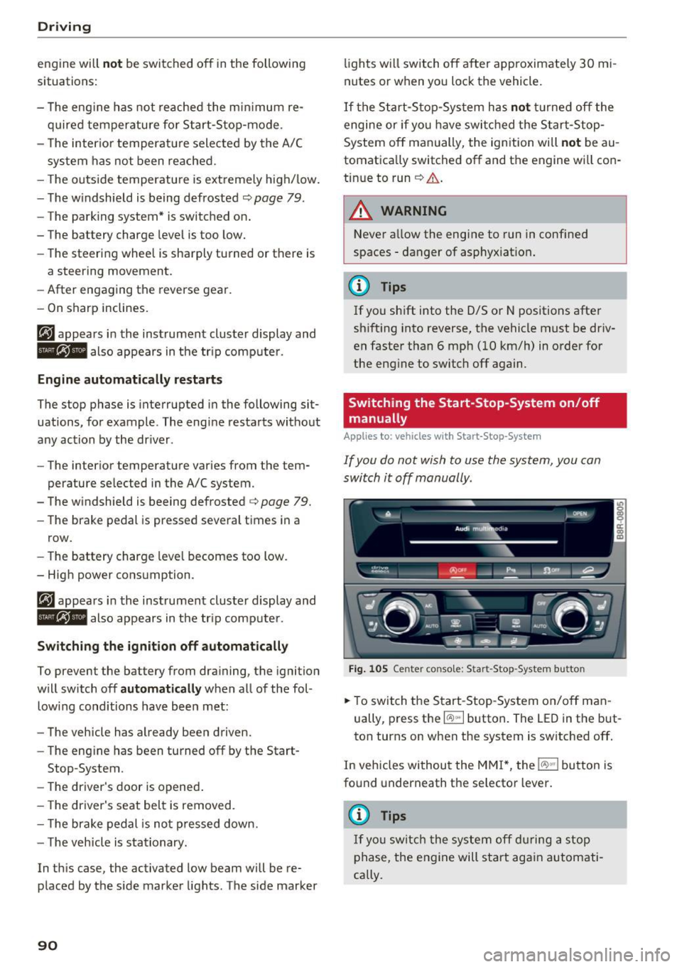
F ig . 10 5 Ceri ter co nsole: S tar t-Stop -System bu tton
.. To swit ch the Start-Stop -System on/off man
ually, press t he
l(A) .. I button . The LED in the but·
ton turns on when the system is switched off .
I n vehicles withou t the MMI*, the
l(A)"'I button is
fo und underneath the se lector lever.
(D Tips
I f yo u swit ch the sy stem off dur ing a stop
p hase, the engi ne will start ag ain automati·
cally .