display AUDI Q5 2021 Owner´s Manual
[x] Cancel search | Manufacturer: AUDI, Model Year: 2021, Model line: Q5, Model: AUDI Q5 2021Pages: 332, PDF Size: 118.86 MB
Page 128 of 332
High-voltage system
of the possible charging display colors under
=> page 127.
The charging connector is locked while charging
and cannot be removed.
If the driver's door is opened while the ignition is
switched off, the current battery charge level and
the high-voltage battery range will be displayed
in the instrument cluster. If charging is in prog-
ress, the remaining charging time will also be
displayed.
Immediate charging and timer charging
You can switch between the immediate charging
@ and charging timer @ options during the
charging process if a charging timer is set
= page 127. Press the corresponding button to
do this.
Ending the charging process
You can interrupt the charging process at any
time.
— Unlock the vehicle or press the @/@) button
when the vehicle is unlocked, and the LED will
turn on.
— Remove the charging connector. If the charging
connector is not removed within 30 seconds, it
will automatically relock and the charging proc-
ess may continue.
— Put the cap back on the charging port.
— Close the charging port door.
— Disconnect the charging cable from the power
supply if necessary or return it securely to the
charging station.
— Install the protective caps on the charging ca-
ble again.
— Ifyou are transporting the charging cable in
the vehicle, store it securely > page 130.
If the charging connector cannot be removed,
you must unlock it manually > page 128.
If you cannot disconnect the charging connector
from the charging station, authenticate yourself
126
again at the charging station and then try again
to disconnect the charging connector. If you still
cannot disconnect the charging connector from
the charging station, contact the charging sta-
tion operator.
ZA WARNING
— Do not disconnect the charging cable from
the socket or the vehicle charging port while
the vehicle is charging. End the charging
process before removing the charging cable
from the socket in order to reduce the risk of
damaging the connector contacts from
sparks.
—If the charging unit is damaged, do not
charge using the charging port to reduce the
risk of injury.
— If the charging unit is damaged or the
charging port door cannot close or is miss-
ing, drive immediately to an authorized Audi
dealer or authorized Audi Service Facility
and have the malfunction corrected to re-
duce the risk of injury.
C) Note
If you drive with the charging unit open, both
the charging port door and the electronics in-
stalled behind it could be damaged. Check
each time after charging if the port door is
locked before you start driving the vehicle.
@ Tips
— If the parking brake is set, it could create
noises
when the charging connector is con-
nected.
— Remove ice and snow in the charging unit
using a hand brush and solvent-free deicing
spray.
— The vehicle radio and TV systems may have
limited reception when charging the vehicle.
Page 129 of 332
80B012721BA
High-voltage system
Charging display
Applies to: vehicles with plug-in hybrid drive
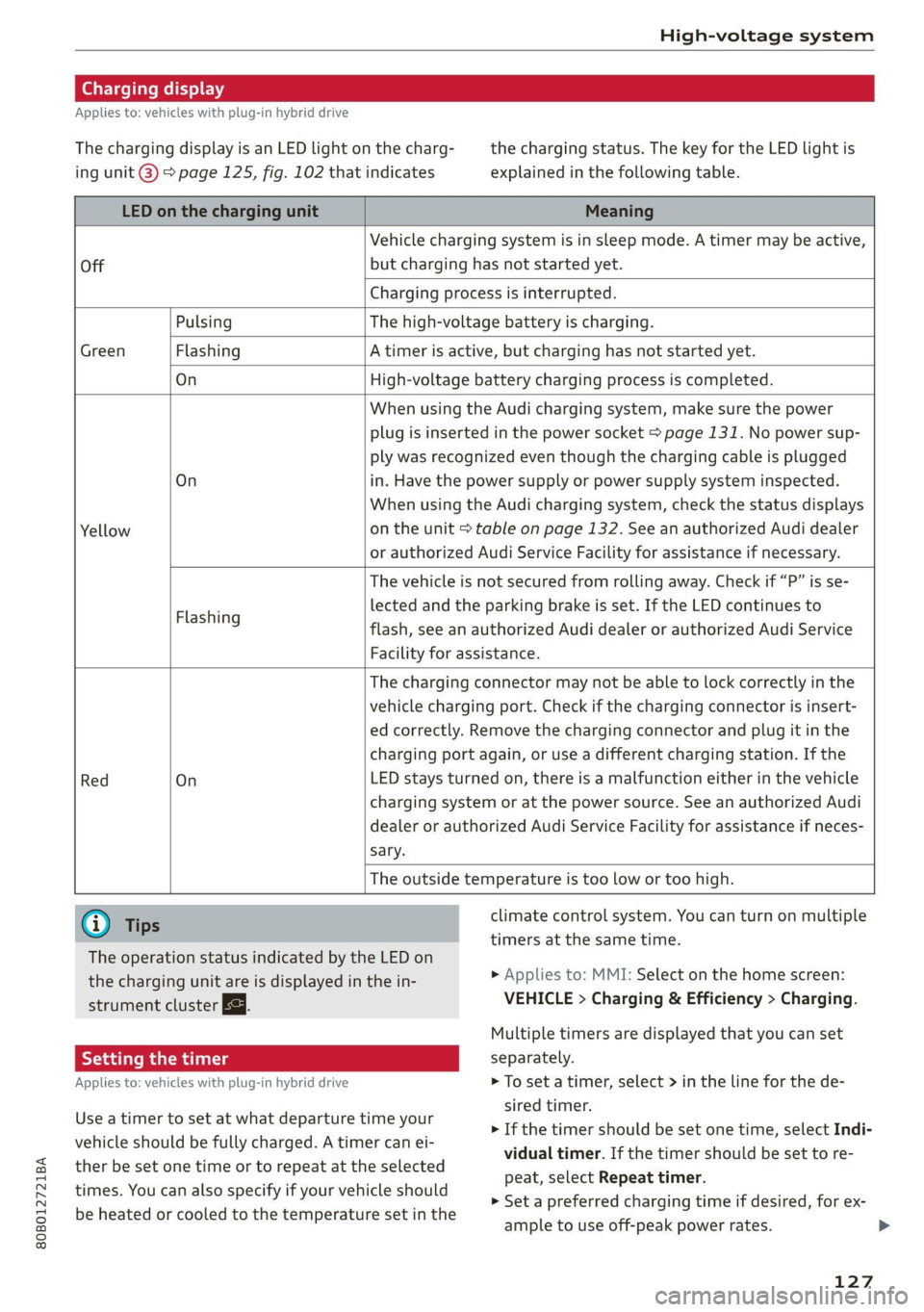
The charging display is an LED light on the charg- the charging status. The key for the LED light is
ing unit @) page 125, fig. 102 that indicates explained in the following table.
LED on the charging unit Meaning
Vehicle charging system is in sleep mode. A timer may be active,
Off but charging has not started yet.
Charging process is interrupted.
Pulsing The high-voltage battery is charging.
Green Flashing A timer is active, but charging has not started yet.
On High-voltage battery charging process is completed.
When using the Audi charging system, make sure the power
plug is inserted in the power socket > page 131. No power sup-
ply was recognized even though the charging cable is plugged
On in. Have the power supply or power supply system inspected.
When using the Audi charging system, check the status displays
Yellow on the unit > table on page 132. See an authorized Audi dealer
or authorized Audi Service Facility for assistance if necessary.
The vehicle is not secured from rolling away. Check if “P” is se-
lected and the parking brake is set. If the LED continues to
flash, see an authorized Audi dealer or authorized Audi Service
Facility for assistance.
Flashing
The charging connector may not be able to lock correctly in the
vehicle charging port. Check if the charging connector is insert-
ed correctly. Remove the charging connector and plug it in the
charging port again, or use a different charging station. If the
Red On LED stays turned on, there is a malfunction either in the vehicle
charging system or at the power source. See an authorized Audi
dealer or authorized Audi Service Facility for assistance if neces-
sary.
The outside temperature is too low or too high.
@ Tips climate control system. You can turn on multiple
timers at the same time.
The operation status indicated by the LED on
the charging unit are is displayed in the in-
strument cluster Eg.
> Applies to: MMI: Select on the home screen:
VEHICLE > Charging & Efficiency > Charging.
Multiple timers are displayed that you can set
Applies to: vehicles with plug-in hybrid drive > To set a timer, select > in the line for the de-
sired timer.
> If the timer should be set one time, select Indi-
vidual timer. If the timer should be set to re-
peat, select Repeat timer.
> Set a preferred charging time if desired, for ex-
ample to use off-peak power rates. >
Use a timer to set at what departure time your
vehicle should be fully charged. A timer can ei-
ther be set one time or to repeat at the selected
times. You can also specify if your vehicle should
be heated or cooled to the temperature set in the
127
Page 130 of 332
High-voltage system
> To also activate the climate control with a tim-
er, select CD.
> Select Next and follow the instructions in the
menu.
> To turn ona timer, select CD.
> To activate an enabled timer, select s+ until the
Timer charging mode is displayed.
If the set departure time on the timer is too
close, it may not be possible to charge the vehicle
fully.
It is not possible to charge using the timer at
some charging stations.
Emergency release
Applies to: vehicles with plug-in hybrid drive
In case of malfunction, you can manually release
the charging port door or the charging connec-
tor.
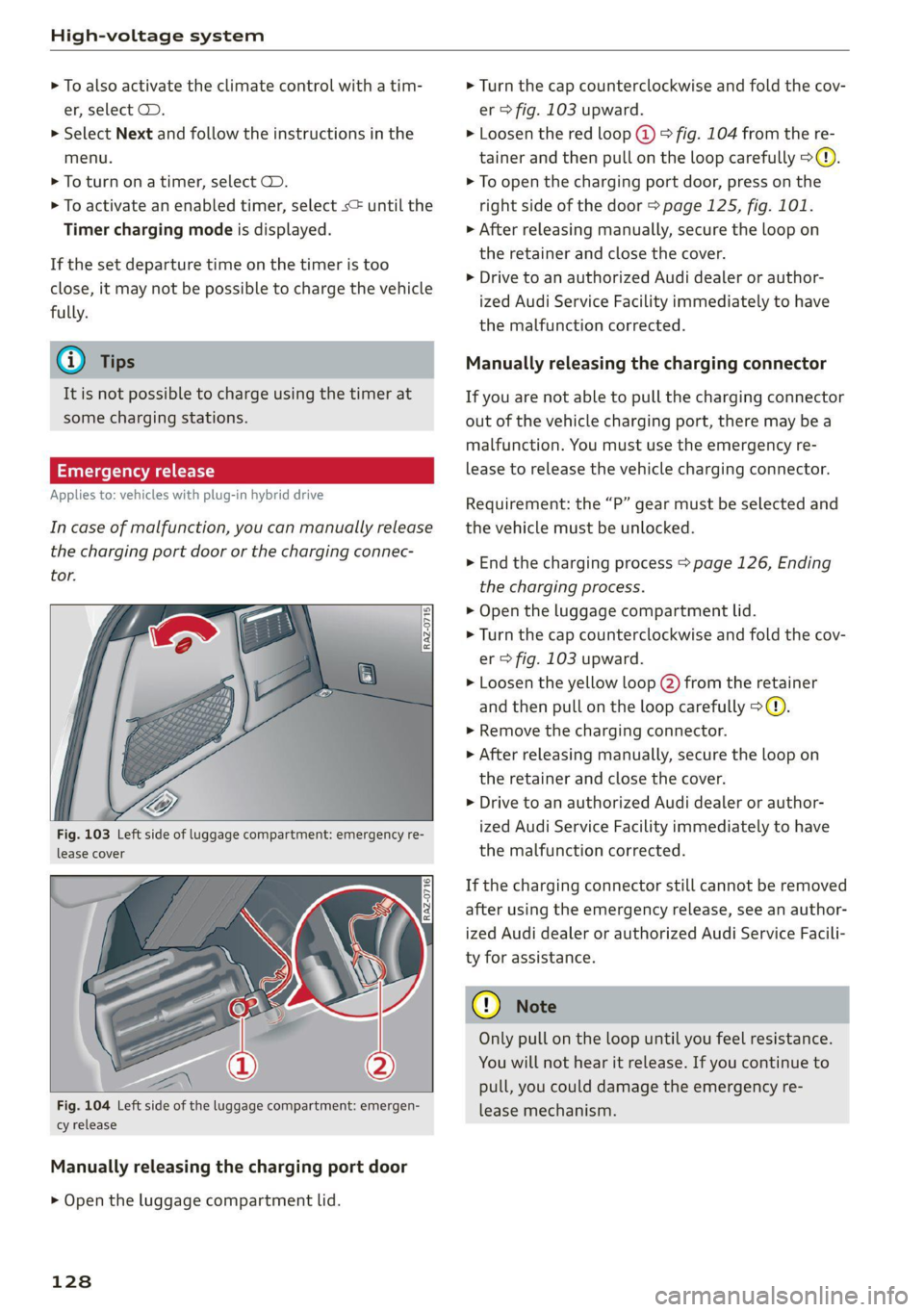
Fig. 103 Left side of luggage compartment: emergency re-
lease cover
[RAz-0716]
Fig. 104 Left side of the luggage compartment: emergen-
cy release
Manually releasing the charging port door
> Open the luggage compartment lid.
128
> Turn the cap counterclockwise and fold the cov-
er > fig. 103 upward.
> Loosen the red loop @) > fig. 104 from the re-
tainer and then pull on the loop carefully >@.
> To open the charging port door, press on the
right side of the door > page 125, fig. 101.
» After releasing manually, secure the loop on
the retainer and close the cover.
> Drive to an authorized Audi dealer or author-
ized Audi Service Facility immediately to have
the malfunction corrected.
Manually releasing the charging connector
If you are not able to pull the charging connector
out of the vehicle charging port, there may bea
malfunction. You must use the emergency re-
lease to release the vehicle charging connector.
Requirement: the “P” gear must be selected and
the vehicle must be unlocked.
> End the charging process > page 126, Ending
the charging process.
> Open the luggage compartment lid.
> Turn the cap counterclockwise and fold the cov-
er > fig. 103 upward.
> Loosen the yellow loop (2) from the retainer
and then pull on the loop carefully >@®.
> Remove the charging connector.
>» After releasing manually, secure the loop on
the retainer and close the cover.
> Drive to an authorized Audi dealer or author-
ized Audi Service Facility immediately to have
the malfunction corrected.
If the charging connector still cannot be removed
after using the emergency release, see an author-
ized Audi dealer or authorized Audi Service Facili-
ty for assistance.
Only pull on the loop until you feel resistance.
You
will not hear it release. If you continue to
pull, you could damage the emergency re-
lease mechanism.
Page 133 of 332
80B012721BA
High-voltage system
Audi e-tron compact charging system
Applies to: vehicles with Audi e-tron compact charging system
a |
m=)
[RAZ-0726|
72
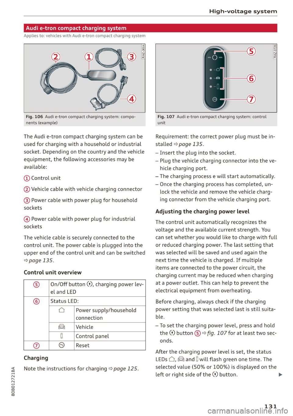
Fig. 106 Audi e-tron compact charging system: compo-
nents (example)
The Audi e-tron compact charging system can be
used for charging with a household or industrial
socket. Depending on the country and the vehicle
equipment, the following accessories may be
available:
@ Control unit
@ Vehicle cable with vehicle charging connector
@®) Power cable with power plug for household
sockets
@ Power cable with power plug for industrial
sockets
The vehicle cable is securely connected to the
control unit. The power cable is plugged into the
upper end of the control unit and can be switched
=> page 135.
Control unit overview
© | On/Off button @, charging power lev-
el and LED
© _ |Status LED:
a Power supply/household
connection
& | Vehicle
0 Control panel
Reset
® 9
Charging
Note the instructions for charging > page 125.
Fig. 107 Audi e-tron compact charging system: control
unit
Requirement: the correct power plug must be in-
stalled > page 135.
— Insert the plug into the socket.
— Plug the vehicle charging connector into the ve-
hicle charging port.
— The charging process e will start automatically.
— Once the charging process has completed, un-
lock the vehicle and remove the vehicle charg-
ing connector from the vehicle charging port.
Adjusting the charging power level
The control unit automatically recognizes the
voltage and the available current strength. You
can set whether you would like to charge with full
or reduced charging power. The last setting that
was selected will be saved and used again the
next time the vehicle is charged. If multiple
items are connected to the power circuit, the
charging current may be reduced when charging
at a power outlet. This can help to prevent the
electrical equipment from overheating.
Before charging, always check if the charging
power setting that was selected last is still suita-
ble.
—To set the charging power level, press and hold
the ® button © © fig. 107 for at least two sec-
onds.
After the charging power level is set, the status
LEDs (, {and [| will flash green one time. The
selected value (50% or 100%) is displayed on the
left or right side of the ® button.
131
>
Page 142 of 332
Trailer towing
You can also increase ground clearance by select-
ing the Audi drive select* Offroad or allroad
modes > page 115.
@) Note
Applies to: vehicles with air suspension
— Changes in temperature or load can affect
the height of the vehicle.
— If the standard vehicle height is not used,
the tongue weight specification is no longer
applicable.
©) Note
Attachments retrofitted on the vehicle may
cause damage, especially on the trailer hitch
ball head. In cases of damage, have the func-
tion checked by an authorized Audi dealer or
authorized Audi Service Facility.
@) Tips
— Block the wheels with chocks when parking
on inclines if the trailer is loaded.
— Audi recommends having the vehicle in-
spected between the inspection intervals if
you tow a trailer frequently.
— Avoid driving with a trailer during the vehi-
cle break-in period.
PTL RR CT Coe
Driving with a trailer requires extra caution.
Speed
Adhere to the legal speed limits. Follow the legal
regulations that are applicable in the country
where you are operating the vehicle.
As the speed increases, the driving stability of
the trailer decreases. Therefore you should not
exceed the maximum legal speed limit when
there are unfavorable road, weather, and/or wind
conditions. This especially applies when driving
downhill.
Hill
When you start driving uphill or downhill, trailers
may tilt or sway sooner than when driving ona
level surface. If small swaying movements have
140
already occurred, you can stabilize the trailer by
firmly braking immediately. Never attempt to
“straighten out” the trailer by accelerating.
Downshift before driving on hills to utilize the en-
gine braking effect > A\.
Brakes
When using a trailer with overrun brakes, first
brake gently then quickly. This reduces the risk of
jerking while braking if the trailer wheels lock up.
Engine coolant temperature
Pay attention specifically to the coolant tempera-
ture display when there are high outside temper-
atures, and when driving on long inclines
= page 14. Shift to a higher gear in a timely man-
ner.
Z\ WARNING
Constant braking causes the brakes to over-
heat and can substantially reduce braking per-
formance, increase braking distance, or cause
complete failure of the brake system.
Page 143 of 332
80B012721BA
Assist systems
Assist systems
General information
Sra eel delay
ZA\ WARNING
— As the driver, you are always completely re-
sponsible for all driving tasks. The assist
systems cannot replace the driver's atten-
tion. Give your full attention to driving the
vehicle, and be ready to intervene in the
traffic situation at all times.
— Activate the assist systems only if the sur-
rounding conditions permit it. Always adapt
your driving style to the current visual,
weather, road, and traffic conditions.
— Loose objects can be thrown around the ve-
hicle interior during sudden driving or brak-
ing maneuvers, which increases the risk of
an accident. Store objects securely while
driving.
— For the assist systems to be able to react
correctly, the function of the sensors and
cameras must not be restricted. Note the in-
formation on sensors and cameras
=> page 142.
@ Tips
— Pay attention to applicable local regulations
relating to driving tasks, leaving space for
emergency vehicles, vehicle distance, speed,
parking location, wheel placement, etc. The
driver is always responsible for following
the laws that are applicable in the location
where the vehicle is being operated.
— You can cancel a steering or braking inter-
vention by the system, by braking or accel-
erating noticeably, steering, or deactivating
the respective assist system.
— Always check the assist systems settings be-
fore driving. The settings could have been
changed, for example by other drivers.
System limitations
ZA\ WARNING
—The use of an assist system cannot over-
come the natural laws of physics. A collision
cannot be prevented in certain circumstan-
ces.
— Warnings, messages, or indicator lights may
not be displayed or initiated on time or cor-
rectly, for example, if vehicles are approach-
ing very fast.
— Corrective interventions by the assist sys-
tems, such as steering or braking interven-
tions, may not be sufficient or they may not
occur. Always be ready to intervene.
@) Tips
— Due to the system limitations when detect-
ing the surrounding area, the systems may
warn or intervene unexpectedly or too late
in certain situations. The assist systems may
also interpret a driving maneuver incorrectly
and then warn the driver unexpectedly.
— The systems may not function as expected
in unusual driving situations, such as driving
offroad, on unpaved roads, on loose ground,
on inclines, or on grooves in the road.
— The systems may not function correctly in
unclear traffic situations, such as turning
lanes, exit ramps, construction zones, rises
or dips that obstruct visibility, intersections,
toll stations, or city traffic.
— The detection of the surrounding area can
be limited, for example by vehicles driving
ahead or by rain, snow, heavy spray, or light
shining into the camera.
—In trailer mode, some assist systems may be
limited, may not react as usual, or may be
unavailable. Please refer to the instructions
for towing a trailer located in > page 138.
— The steering wheel touch recognition may
be limited when you wear gloves. Steering
intervention requests from the steering as-
sist systems may occur more frequently.
— If accessories have been mounted on the
steering wheel, the steering assist systems
may
be limited. The frequency of steering
141
>
Page 144 of 332

Assist systems
intervention requests from the steering as-
sist systems may vary as well.
Surrounding area
detection
Sensor and camera coverage areas
RAZ-1071
Fig. 111 Rearview camera coverage area
The assist systems analyze the data from various
sensors and cameras installed in the vehicle. Do
not use any assist systems if there is damage in
there area of the sensors and cameras or on the
vehicle underbody. Damage can impair the func-
tion of the sensors and cameras or cause mal-
functions. Have an authorized Audi dealer or au-
thorized Audi Service Facility check their func-
tion.
142
Radar sensors
Depending on the vehicle equipment, the area
surrounding the entire vehicle may be detected
> fig. 110.
The wheel sensors on the rear corners of the vehi-
cle are positioned so that the adjacent lanes to
the left and right are detected on roads with a
normal lane width.
Ultrasonic sensors
Depending on vehicle equipment, various areas
may be displayed in the MMI using the ultrasonic
sensors > fig. 110.
The range of the displays depends on the location
of the ultrasonic sensors:
@ Approximately 4 ft (1.20 m)
® Approximately 3 ft (0.90 m)
@® Approximately 5.2 ft (1.60 m)
©® Approximately 3 ft (0.90 m)
© Approximately 3 ft (0.90 m)
The side area ©) is detected and evaluated when
passing. There may have been changes to the sur-
rounding area after switching the ignition off and
on again, after opening the doors, or if the vehi-
cle is left stationary for a period of time. In this
case, the area will appear black until the area has
been detected and evaluated.
Cameras
Use the camera image on the display to assist you
only if it shows a good, clear picture. Keep in
mind that the image in the display is enlarged
and distorted. Under certain circumstances, ob-
jects may appear different and unclear on the dis-
play.
The rearview camera can only detect the area
marked in red > fig. 111. Only this area is dis-
played on the center display. > A\.
ZX WARNING
Sensors and cameras have spots in which the
surrounding area cannot be detected. Objects,
animals, and people may only be detected
with limitations may not be detected at all.
Always monitor the traffic and the vehicle's >
Page 145 of 332
80B012721BA
Assist systems
surroundings directly and do not become dis-
tracted.
() Note
— Obstacles may disappear from the measure-
ment range when approaching them, even if
they were already detected.
—Insome situations, the ability of the sen-
sors and cameras to detect and display cer-
tain objects may be limited.
— Objects located above the coverage area,
such as bumpers on parked cars, garage
doors that are partially open, or objects
that are hanging
— Low obstacles
— Narrow objects, such as barrier chains, fo-
liage, poles, or fences
— Projecting objects, such as trailer draw
bars
— Objects with certain surfaces and struc-
tures,
such as fabric
@) Tips
— The sensors and cameras and the areas
around them must not be obstructed be-
cause this can impair the function of the
systems that depend on them. Make sure
that the sensors and cameras are free of
snow, ice, and other deposits. Do not use
any accessories, stickers, or other objects
that extend into the range of the sensors
and cameras.
— On vehicles that have factory-installed li-
cense plate brackets on the front of the ve-
hicle, the brackets may only be replaced
with ones that are the same size and made
of the same material. Do not install any li-
cense plate brackets on the front of vehicles
that do not have factory-installed brackets.
Otherwise, the function of the system could
be impaired.
— The function of the sensors and cameras
may be limited when light and visibility con-
ditions are poor, for example when driving
into
a tunnel, when there is glare, or when
there are reflective objects.
— External ultrasonic sensors, such as those in
other vehicles, can interfere with the sen-
sors.
— The coverage areas of the sensors > fig. 110
and cameras > fig. 111 are diagrams and do
not represent a true-to-scale image of the
sensor ranges.
— The system complies with United States FCC
regulations and ISED regulations
=> page 311.
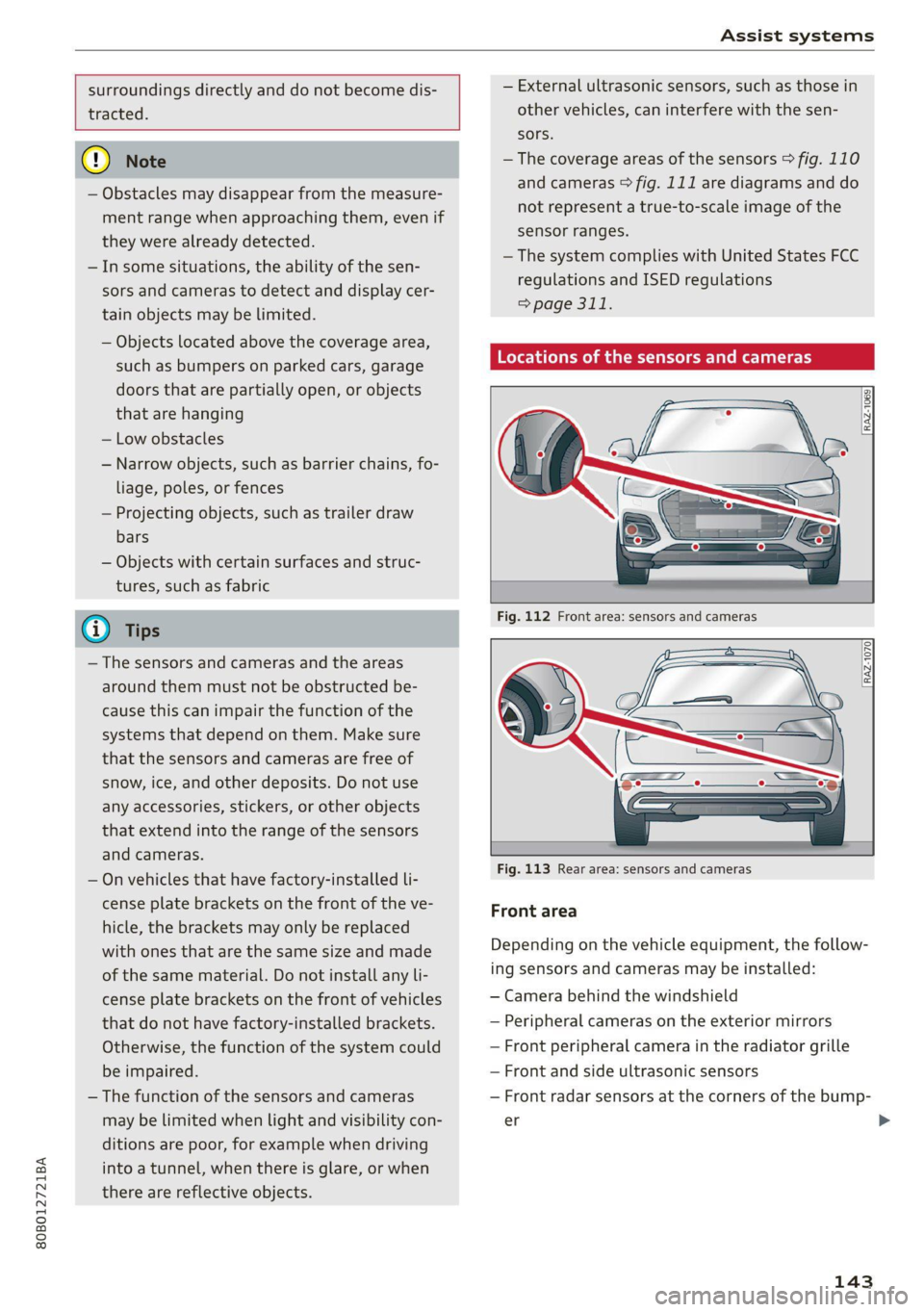
Locations of the sensors and cameras
[RAZ-1069
Fig. 113 Rear area: sensors and cameras
Front area
Depending on the vehicle equipment, the follow-
ing sensors and cameras may be installed:
— Camera behind the windshield
— Peripheral cameras on the exterior mirrors
— Front peripheral camera in the radiator grille
— Front and side ultrasonic sensors
— Front radar sensors at the corners of the bump-
er
143
>
Page 147 of 332
80B012721BA
Driving information
Driving information
Speed warning system
Applies to: vehicles with speed warning system
The speed warning system helps the driver to
stay below a specified maximum speed. A warn-
ing threshold can be set in the MMI for this pur-
pose.
Once the speed slightly exceeds the stored
threshold, the speed warning system will alert
the driver with an indicator in the instrument
cluster and a warning tone. Once the speed drops
below the stored maximum speed, the indicator
will turn off.
Setting a threshold is recommended if you would
like to be reminded when you reach a certain
maximum speed. Situations where you may want
to do so include driving in a country with a gener-
al speed limit or if there is a specified maximum
speed for winter tires.
@) Tips
Regardless of the speed warning system, you
should always monitor your speed using the
speedometer and make sure you are adhering
to the legal speed limit.
Setting the warning threshold
Applies to: vehicles with speed warning system
> Applies to: MMI: Select on the home screen:
VEHICLE > Driver assistance > Speed warning.
Messages
Applies to: vehicles with speed warning system
iol Manually set speed limit XX mph
(km/h) exceeded
The stored speed was exceeded.
Camera-based traffic
sign recognition
Applies to: vehicles with camera-based traffic sign recognition
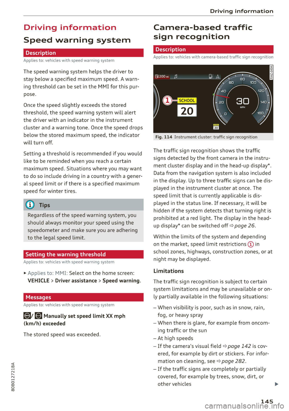
Fig. 114 Instrument cluster: traffic sign recognition
The traffic sign recognition shows the traffic
signs detected by the front camera in the instru-
ment cluster display and in the head-up display”.
Data from the navigation system is also included
in the display. Up to three traffic signs can be dis-
played in the instrument cluster at once. The
speed limit that is currently applicable is dis-
played in the status line. If necessary, it will be
hidden if the system detects that turning right is
prohibited at a red light. The display in the head-
up display* can be switched off > page 26.
Within the limits of the system and depending
on the market, speed limit restrictions @ in
school zones, highways, construction zones, or at
night may be displayed.
Limitations
The traffic sign recognition is subject to certain
system limitations and may be unavailable or on-
ly partially available in the following situations:
— When visibility is poor, such as in snow, rain,
fog, or heavy spray
— When there is glare, for example from oncom-
ing traffic or the sun
— At high speeds
— If the camera's visual field > page 142 is cov-
ered, for example by dirt or stickers. For infor-
mation on cleaning, see > page 282.
— If the traffic signs are completely or partially
covered, for example by trees, snow, dirt, or
other vehicles
145
Page 148 of 332
Driving information
— If traffic signs do not conform to the standard
format
— If traffic signs are damaged or bent
— If traffic signs are displayed on sign holders
with electronic signs
— If the traffic signs or the roadways have
changed, and the navigation data is no longer
up-to-date
Z\ WARNING
— Observe the safety precautions and note the
limits of the assist systems, sensors, and
cameras > page 141.
— Under some circumstances, traffic sign rec-
ognition may not detect traffic signs correct-
ly or detect them at all. As a result, the sys-
tem may not display the correct speed limit
or any speed limit.
@) Tips
— Traffic sign recognition does not adapt your
vehicle's speed to match the speed Limit.
— The display in the instrument cluster is
based on the units of measurement used for
speed in the country where the vehicle is be-
ing operated. As a result, a display of 50 in
the instrument cluster can mean either mph
or km/h, depending on the country.
Applies to: vehicles with camera-based traffic sign recognition
Accessing traffic sign recognition
> Select in the instrument cluster: vehicle func-
tions tab > Traffic signs.
Setting a traffic sign based speed warning
> Applies to: MMI: Select on the home screen:
VEHICLE > Driver assistance > Speed warning.
You can select a warning threshold. If you exceed
this, then the current detected speed limit will be
shown in the display with an exclamation point
for the duration that it is exceeded and it will
blink for a short time.
146
IY ett Tel -1
Applies to: vehicles with camera-based traffic sign recognition
Traffic sign recognition: unavailable. Camera
view limited due to environm. conditions
The camera’s visual field is covered. Clean the
windshield.
Traffic sign recognition: currently limited.
See owner's manual
This message appears if navigation system data
is not available, for example on newly-construct-
ed roads. The speed limit display will be tempo-
rarily limited, which increases the risk of an incor-
rect display. If this message continues to appear,
drive immediately to an authorized Audi dealer or
authorized Audi Service Facility to have the mal-
function repaired.
No traffic sign information available
Depending on the area, there is no valid naviga-
tion data and no speed limits were detected. This
may also appear if there is a recommended
speed, but no speed limit (for example when
driving on and off the expressway).
Malfunction! See owner's manual
The system may not function correctly so it has
been switched off. See an authorized Audi dealer
or authorized Audi Service Facility for assistance.
Function currently unavailable. See owner's
manual
If this message appears on vehicles without cam-
era-based traffic sign recognition, then the traffic
light
information function is currently unavaila-
ble. See > page 148.