AUDI Q7 2010 Owner´s Manual
Manufacturer: AUDI, Model Year: 2010, Model line: Q7, Model: AUDI Q7 2010Pages: 390, PDF Size: 93.04 MB
Page 171 of 390
______________________________________________ _:P_ a=.:... r:.:k ;.:in :..:.;;; g!.....:: s.,?.y .=s :..:t :.:e :.: m...:..:.._..J_
Parking system advanced
App lies to veh icles: wit h pa rk ing syste m advanced
Introduction
0, g ~ ..!J
~================- i
Fig. 166 Parking
model: Backing into a
parking space
Fig. 167 Parking
mode 2: parallel
parking
Vehicles with the parking system advanced are equipped with a rear
view camera
in addition to the acoustic and visual parking system.
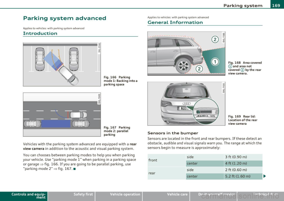
You can chooses between parking modes to help you when parking
your vehicle. Use "parking mode
1" when parking in a parking space
or garage~ fig. 166 .
If you are going to be parallel parking, use
"parking mode
2" ~ fig. 167. •
Contro ls a nd e quip
m en t Vehicle
OP-eration
Applies to vehicles : w ith par kin g system advanced
General Information
Sensors in the bumper
Fig. 168 Area covered
@ and area not
covered @
by the rear
v iew camera.
Fig. 169 Rear lid:
Location of the rear
view camera
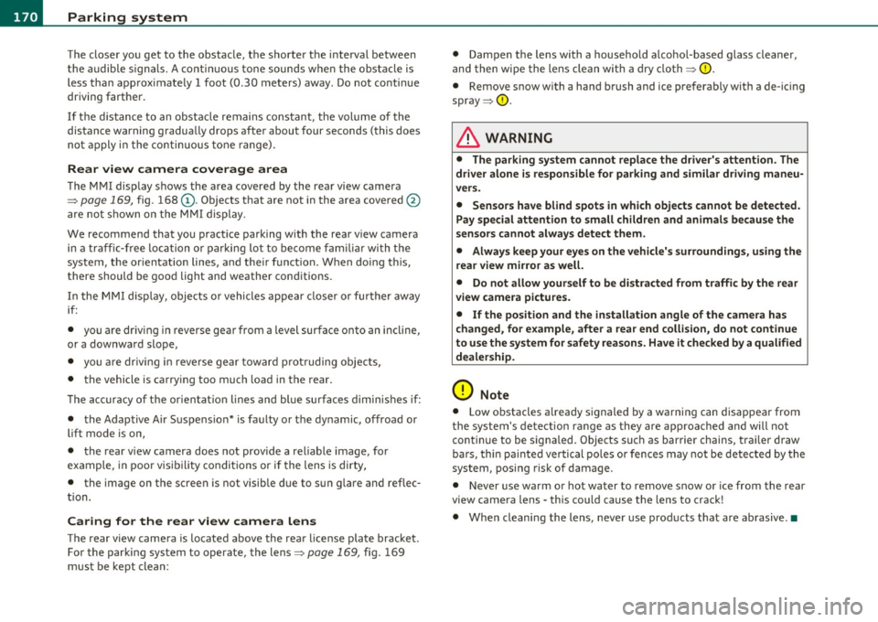
Sensors are located in the front and rear bumpers . If these detect an
obstacle, audible and visual signals warn you. The range at which the
sensors begin to measure is approximately:
front
rear side
center
side
center
Vehicle care
3 ft (0
.90 m)
4 ft (1.20 m)
2 ft (0.60 m)
5.2 ft (1.60 m)
Do-it-yourselt service iTechnical data
Page 172 of 390
lffl!IL-___;P:....:: a:.:.r..:.k .:.: i.:..n .:.:g:!....: s:.: y~ s..:t ..:e ..:.m .:..:... _______________________________________________ _
The closer you get to the obstacle, the shorter the interval between
t he audible s ignals. A contin uous tone sounds whe n the obstacle is
less than approximately 1 foot (0 .30 meters) away . Do not co ntin ue
driving farther.
If the distance to an obstacle remains constant, the volume of the
distance warning gradually drops after about four seconds (this does
no t a pply in the co nti nuous to ne range).
Rear view camer a coverage area
The MMI display shows the area covered by the rear v iew camera
=> page 169, fig . 168 (D. Objects that are not in the area covered@
are not shown on the M MI display.
We recommend that you practice parking with the rear v iew camera
in a traff ic -free location o r parki ng lo t to become fam iliar wi th t he
system, the orientation lines, and the ir funct ion . When do ing th is,
there should be good lig ht and weather cond itions.
In the MM I disp lay, objects o r vehicles appea r closer or fu rther away
if:
• you are dr iv ing in r everse gea r from a level surface onto an incline,
or a downwa rd slope,
• you a re driving i n reve rse gear toward p rot ruding objec ts,
• the vehicle is carry ing too much load in the rear.
T he accur acy of the or ien tat io n lines and blue su rf a ces dimin ishes if:
• the Adaptive Air Suspens ion* is faulty or the dynamic, offroad or
lift mode is on,
• the rear view camera does not prov ide a reliable image, for
example, in poor visib ility conditions or if the lens is dirty,
• the image on the screen is not visible due to sun g lare and ref lec
ti on .
Caring for the rear view camera lens
The rear view came ra is lo cated above the rea r license plate bracke t.
For the parking system to ope rate, the lens=>
page 169, fig. 169
must be kept clean: •
Dampen the lens with a househo ld alcoho l-based glass cleaner,
and then wipe the lens clean with a dry cloth =>
CD.
• Remove snow with a hand brush and ice preferably with a de-ic ing
spray =>
CD.
& WARNING
• The parking sy stem cannot replace the dri ver's attention . The
d river alone i s respo nsible for p arking and sim ila r dri ving maneu
ver s.
• Sensor s hav e blind spots in which objects cannot be detected.
Pa y s peci al att ention to small children and animal s beca u se the
sen so rs cannot al ways detect them.
• Alway s keep your e yes on the v ehicle's surr ound ing s, u sing the
r ear view mirror as well.
• Do not all ow your self to be distract ed from traffic by the r ear
v iew camera pictu res .
• If the position and the installation angle of th e camera has
changed , for e xample, after a rear end colli sion, do not continu e
to use th e system for safety r ea son s. Hav e it check ed by a qualified
deale rship.
0 Note
• Low obstacles a lready signaled by a warning can disappear from
the system's detection range as they are approached and will not
continue to be signaled . Objects such as barrier chains, trai ler draw
bars, th in pa inted vertical po les or fences may not be detec ted by the
system, posing risk of damage.
• Never use warm or hot water to remove snow or ice from the rear
view camera lens -this co uld cause the lens to crack!
• When cleaning the lens , never use products that are abrasive .•
Page 173 of 390

Parking system -
----------------=-------'
Applies to veh icles : w ith par king system advanced
Switching on and off
Th e rear view camera switches on automatically together
with the acoustic and visual park assist when you put the
vehicle in reverse.
Switching on
F ig. 170 Cente r
c on sole: Pa rki ng
sys tem swi tch
Fig . 171 MMI display:
v is ual d istance disp la y
- Switch the MMI on and select reverse gear.
- Switch on the Adaptive Air Suspension * comfort or auto-
matic mode .
Contro ls a nd e quip
m en t Vehicle
OP-eration
-To use the front parking system , press the switch P11.1A in the
center console ~ fig . 170 . A short confirmat ion tone
sou nds an d the indicator light in the sw itch lights up.
Switching between the rear view camera and
visual display
- Press the Graphic control button~ page 172, fig. 172 ®
to see the visual dis pla y.
- P ress the
Rear view control button to see the rear view
camera image~ fig . 171.
Switching off
Drive faster than 6 mph ( 10 km/h), or
- press th e swi tch
P111 A or
- switch off the ignition .
Segments in the visual display
The red segments i n front of and behind the vehicle=> fig . 171 help
you to determine the distan ce between you and an obstacle . As your
vehicle comes closer to the obstacle, the segm ents move closer to the
veh icle . The co llision area has been reached when t he next to last
segmen t is displayed . Do not cont inue dr iv ing farthe r=>
& in
"Ge neral Information " on
page 169!
& WARNING
• The MMI display cannot show , or cannot adequately show ,
c ertain objects (such a s small posts or grating ), reces ses in the
ground and protruding parts on another car.
• Onl y use the rear view camera to a ssist you if it show s a good ,
clear picture. For e xample, the image may be affected by the sun
shining into the lens , dirt on the len s or if there is a defect. .,_
Vehicle care Do-it-yourselt service iTechnical data
Page 174 of 390
Ill Parking system
"---~--------------
& WARNING (continued)
• Use the rear view camera only with the rear lid completely
closed. Make sure any objects you may have mounted on the rear
lid do not block the rear view camera.
[ i ) Tips
• The sensors must be kept clean and free of snow and ice for the
park assist to operate.
• The visual display is shown in the illustration of the rear view
camera . This display shows where the sensors have detected an
obstacle.
• You can change the volume and pitch of the signals as well as the
display =>poge
174.
• Please follow the instructions for towing a trailer=> page 175 .
• What appears in the display is time-delayed. •
Applies to veh icles: wit h pa rking sy ste m adv anc ed
Reverse Parking
Parking mode 1 can be used when parking in a garage or
into a parking space.
Fig. 172 MMI display:
aiming at a parking
spot Fig. 173
MMI display:
aligning the vehicle
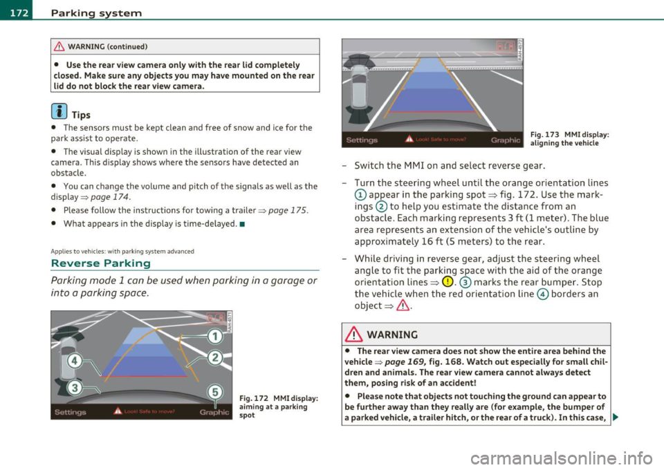
-Switch the MMI on and select reverse gear.
- Turn the steering wheel until the orange orientation lines
(D appear in the parking spot=> fig. 172. Use the mark
ings @to help you estimate the distance from an
obstacle. Each marking represents 3
ft (1 meter) . The blue
area represents an extension of the vehicle's outline by
approximately 16 ft (5 meters) to the rear.
- While driving in reverse gear, adjust the steering wheel
angle to fit the parking space with the aid of the orange
orientation lines=>
0. ® marks the rear bumper. Stop
the vehicle when the red orientation line© borders an
object=> &.
& WARNING
• The rear view camera does not show the entire area behind the
vehicle =>
page 169, fig. 168. Watch out especially for small chil·
dren and animals . The rear view camera cannot always detect
them, posing risk of an accident!
• Please note that objects not touching the ground can appear to
be further away than they really are (for example, the bumper of
a parked vehicle, a trailer hitch, or the rear of a truck). In this case, .,
Page 175 of 390
Parking system -
----------------=-------'
& WARNING (continued )
you should not use the help lines to help with parking, which
poses danger of an accident!
0 Note
In the MMI display , the direction of travel of the vehicle rear is repre
sen te d dependin g on the s teering wheel ang le . The vehicle fron t
swings out more than the vehicle rear. Maintain plenty of distance so
that your outside mirror or a corner of your vehicle does not collide
with any obstacles. This can damage to your vehicle. •
Applies to ve hicles : w ith pa rk ing system advanced
Parallel Parking
Use parking mode 2 to help you parallel pork along the
side of a street.
Con tro ls a nd e quip
m en t
Fig . 174 MMI display:
blue surface in the
parking spot
Vehicle OP-eration
Fig. 175 MMI display:
Blue curve on the curb
The following steps apply only when there is no obstacle such
as a wall near the parking spot. Otherwise, please read the information provided in the "Parking Next to Obstacles"
section.
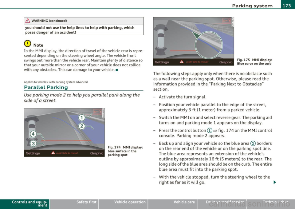
- Activate the turn signal.
- Position your vehicle parallel to the edge of the street,
approximately 3 ft (1 meter) from a parked vehicle.
- Switch the MMI on and select reverse gear . The parking aid
turns on and parking mode 1 appears on the display .
Press the control button©~ fig. 174 on the MMI control
console. Parking mode 2 appears.
- Back up and align your vehicle so the blue area @ borders
on the rear end of the vehicle or on the parking spot line.
The blue area represents an extension of the vehicle's
outline by approximately 16 ft (5 meters) to the rear. The
long side of the blue area should be on the curb. The entire
blue area must fit into the parking spot.
- With the vehicle stopped, turn the steering wheel to the
right as far as it will go. _.,
Vehicle care Do-it-yourselt service iTechnical data
Page 176 of 390
IIII.___P_ a_r_k _ i_n ...::g::- s_, y...._ s_t _e _m ________________________________________________ _
- Back into the parking spot until the blue c urve touches t he
curb==>
page 173, fig. 175 . Stop the vehicle .
- With t he vehicle stopped, turn the steeri ng whee l to the
left as far as it wi ll go.
- Continue to back into the parking spot until the vehicle is
parked paralle l to the curb.@ marks the rear bumper .
Stop the vehic le w hen t he re d orientation line© borders
an object ==>& . Ke ~ an eye on the fro nt o f your ve hicle
whi le doing this==><.!).
Parking next to ob stacles
When there is an obstacle (such as a wall) next to the parking spot,
choose a spo t w it h more space on the sides. Position t he long side of
the blue area so that there is sufficient space from the curb. The area
must not be on the curb. You will also need to star t turning the
steer ing wheel much earlier. There should be a suff icie nt amount of
space between the c urb and the b lue c urve, and t he b lue c urve
=> page 173, fig . 175 must not touch the curb .
& WARNING
• The rear view camer a does not show the entire area beh ind the
vehicle =>
page 169, fig. 168 . Watch out e specially for small chil
dr en and animals. The rear view camera cannot always detect
them, p osing ri sk of an ac cident!
• Please note that object s not touching the g round can appear to
be further away than th ey r eally are (for example, the bumper of
a parked vehicle, a trailer hitch, or th e rear of a t ruck) . In this case,
you should not us e the help line s to h elp with parking , which
po se s danger of an accid ent !
0 Note
In the MMI display, the direct io n of travel of the vehicle rea r is rep re
sented depending on the steering wheel angle . The vehicle front sw
ings out more than the vehicle rear . Maintain plenty of d istance so
t ha t your ou tside mirror or a corner of your vehicle does no t collide
w ith any obstacles . This can damage to you r vehicle.
(I] Tips
The left or right or ientation lines and surfaces w ill be displayed,
depending on the turn signa l being used. •
Applies to vehicles: w it h rear park ass ist/pa rking sys tem advance d
Adjusting the display and warning
tones
T he display * and warning tones can be adjusted in the
fv1 fv1I.
- Select: Function but ton [CAR ]> System s*> Parking
system.
Displ ay*
• Off -when the parking system is switched off, only audible signals
are g iven .
• On -when the parking system is switched on, either the visual
display o r the picture from the rear v iew c amera is displayed.
Warning tones
• Front volume * -front sensor vol ume
• Front frequen cy * -front sensor frequency
• Rear volume -rear sensor vo lume
• Rear frequenc y-rear senso r freq uency
• In-car entertainment fader -when the parking system is switched
on, the vol ume of t he active audio source is lowered.
The newly adjusted va lue is briefly heard from the signal generator . .,
Page 177 of 390

Parking system -
--------------=--=---
[I) Tips
• The warn ing tones can also be adjusted d irectly by the v isua l
display* or the picture from the rear view camera* . Simply press t he
S ettings * control butto n.
• Changed settings are activated when park ing system is switched
on again.
• T he settings are automatically stored and assigned to the remote
control key. •
Applies to veh icles: w ith rear park assist/park ing system advanced and t ra iler h itch
Trailer hitch
For vehicles with a factory installed trailer hitch, or a trailer hitch
ins talled a cco rding to factory specifica tions, the p arking sys tem rear
sensors do not come on whenever you shift into reverse gear or when
you p ress the
P,.,1~ swit ch*. If yo u install a hitch yourse lf, this f unction
may not work. In genera l the follow limitations may come up:
Rear park assist*
There is no warning for distances to the rear.
Parking system advanced *
There is no warning for d istances to the rear. The front sensors
remain act ivated. The v isua l display sw itches to the trailer tow ing
mode. The p icture from the rear v iew camera will not show the orien
tat ion li nes nor the bl ue surfaces. •
Applies to veh icles: with rear park ass ist/park ing sys tem advanced
Error messages
There is an erro r in the system if the LED on the Pwi switc h* is blink ing
and you he ar a continuous alarm for a few se con ds afte r swi tching on
Controls and equip
ment Safety first
the parking system or when the parking system
is a lready activated.
Have your au thor ize d Aud i deale r co rrec t th e error.
[I) Tips
If the er ror is not corrected befo re yo u switch off the ignition, when
you sw itch on the parking system again, the LED in the
P'#A sw itch * will
blink. •
Vehicle care Technical data
Page 178 of 390
lfflJ.___A_ d_ a__,__ p_t_ i_v _e _ A_ i_ r_ S _ u_ s__. p ,_ e_n_ s _ io_ n __________________________________________ _
Adaptive Air Suspension
Air suspension and damping
Applies to veh icles : w ith Adap tive Air Suspens ion
Description
Air suspensi on and damping can be regulated as desired
by driver, and they adapt automatically to the driving
situation at the time.
Adaptive Air Suspens ion is an e lectro nically controlled springing and
damping system . This chass is system makes it eas ie r on the d river by
adapting to the particular situation through imperceptible contro l
processes .
The
Adapt ive Air Suspension component regu lates ground clearance
depending on vehi cle speed and driver input .
It fu nc tions in depen
dently from the load cond itio n. Accele rating to a speed above a
predetermined limi t will ma ke the vehicle lower itse lf . On the other
hand, driv ing more slowly res ults in the vehicle ra is ing again at
specific s peeds.
T he
damping component provides individua l control of the damping
forces. For example, with damping characterist ics set to provide
greater comfort, damp ing is se t somewh at harder for a br ief period
only as req uired, for example, whe n going aro und a curve or when
bra king.
Settings
Ad aptive Air Suspension provides the drive r wi th the opportu nity to
set the chass is characterist ics also to their individual preference.
With the driving modes
Comfort, Au tomatic an d Dynamic the dr ive r
has three chassis sett ings available, ranging from comfort to spo rty.
Th e
Offroad mode c an be selected for dr iv ing on poor qu ality
st retches of road . In addition,
Li~ provides a f ifth mode, w hich can be
selecte d when exceptionally high ground clearance is needed
:::;, page 177, "C hass is controls" . The modes are set
in MM I:::;,
page 178.
& WARNING
The height of the parked vehicle can change due to temperature
fluctuation s or changes in load .
0 Note
• Whenever you park yo ur vehicle, always make sure there is
adeq uate clearance above and below the ve hicle . T he heig ht of the
parked vehicle can change as the res ult of temperature fluctuations,
changes in load condition and changes in the dr iv ing mode (ground
clearance).
• If the veh icle is be ing transported (e .g. by tow truck, train, ship,
etc.) , mount the tie-down cha ins/cables over the r unning s urface
(c ircumfere nce) of the tires. Never sec ure the vehicle by the ax le, the
suspension struts or the front or rear tow line eye. For technical
reaso ns, the p ressure in t he suspension st ru ts m ay change dur ing the
transport, w hic h could result in the vehicle no longer being secured
pro perly.
• If you are going to tow a trailer w ith a tra iler hitch that was
not
ins talled accor ding t o fac tory spe cifica tion s, you mus t activa te t he
trai ler operation mode manually :::;,
page 180.
[ i ] Tips
• Before you ca n raise your vehicle using the vehicle jack (for
examp le, when changi ng a flat tire) o r a veh icle lift , yo u m us t a ct iv a te
the jacki ng mode:::;,
page 180.
• O n some mo dels, the vehicle can reac h its m aximum spee d on ly in
the
Automatic and Dynamic modes .•
Page 179 of 390
____________________________________________ A_ d_a_ p ,_ t_iv _ e_ A _ i_ r _ S_ u_s_, p __ e_n _ s_ i _o_ n __ ffllll
A pp lies to ve hicles : with A dap tive Air Su spen sion
Chassis controls
Five different driving modes can be set by the driver.
The automatic control processes are speed- and time-dependent. For
example, it is not possible to raise the suspension to a high level
above certain speeds.
When a speed of about 75 mph (120 km/h) is exceeded for more than
30 seconds, the vehicle is automatically lowered to
low level when in
comfort and automatic mode. Ground clearance is about 0.6 inch (15
mm) less, compared to the
normal level.
When a speed of about 100 mph (160 km/h) is exceeded for more
than 20 seconds, the vehicle is automatically lowered to
highway
level
when in automatic and dynamic mode . Ground clearance is
about 1.4 inches (35 mm) less, compared to the
normal level. Road
holding is optimized as a resu lt of the lower center of gravity, and fuel
consumption is reduced as a result of reduced wind resistance .
Level adjustment
high level 2
normal level
highway level
Ground clearance
about 9.4 inches (240 mm)
about 8 inches (205 mm)
about 7 inches (180 mm)
about 6.5 inches (165 mm)
about 5. 7 inches (145 mm)
The segment display @ in the MMI Display =>
page 178 or in the
instrument cluste r display =>
page 179 shows the current vehicle
level.
Automatic
Select the automatic mode if you prefer a balanced, comfortable
suspension setting. The damp ing characteristics are adjusted accord
ing ly .
Controls and equip
ment Safety first •
Automatic lowering: When a speed of about 75 mph (120 km/h)
is exceeded for more than 30 seconds, the veh icle is automatically
lowered by about 0 .6 inch (15 mm) to the
low level, which is more
suitable for highway speeds. Road holding is optimized as a result of
the lower center of gravity and fuel consumpt ion is reduced as a
result of reduced wind resistance . When a speed of about 100 mph
(160 km/h) is exceeded fo r more than 20 seconds, the vehicle is auto
matically lowered by an additional 0.8 inch (20 mm) to
highway level.
• Automatic raising: When the vehicle is at highway level and the
speed falls below about 80 mph (130 km/h) for more than 20
seconds, the vehicle is automat ically raised to
low level. The vehicle is
automatically raised again to
normal level if the speed falls below
about 44 mph (70 km/h) for a period of 2 minutes. The vehicle is
raised immediately when speed falls below about 22 mph (35 km/h).
Dynamic
Select the dynamic mode if you prefer a sporty suspension setting . In
this mode, the vehi cle is lowe red to
low level wh ile it is still stationary
and sporty damp ing characteristics a re selected . The warning light
c.:> in the instrument cluster wi ll come on for a few seconds just to
remind you of the reduced ground clearance.
If you switch off the engine whi le the vehicle is in the dynamic mode
and then switch on the ignition once again, the
c.:> warning light will
also come on again for a few seconds as a reminder .
• Automatic lowering : When a speed of about 100 mph (160 km/h)
is exceeded fo r more than 20 seconds, the vehicle is automatically
lowered by 0.8 inch (20 mm) to
highway level.
• Automatic raising: The vehicle is automatically raised to low level
again, if the speed falls below about 80 mph (1 30 km/h) for a per iod
of 20 seconds. The vehicle is raised immediately when speed falls
below about 22 mph (35 km/h).
Comfort
Select the comfort mode if you desire a suspension setting with a
special emphasis on comfort. Damping characteristics with a clear
emphasis on comfort are selected in this mode.
~
Vehicle care Technical data
Page 180 of 390
llffl..__A_ d_a_ p,__ t_iv _ e_ A_ i_r _ S_ u_s _, p'--- e_n _ s_ i_ o _ n ___________________________________________ _
• Automatic lowering: When a speed of about 75 mph ( 120 km/h)
is exceeded for more than 30 seconds, the vehicle is automatically
lowered by 0 .6 inch (15 mm) to
low level .
• Automatic raising: The vehicle is automatically raised to normal
level
again, if the speed falls below about 44 mph (70 km/h) for a
period of 2 minutes . The vehicle is raised immediately when speed
falls below about 22 mph (35 km/h) .
Offroad
Select the offroad mode when you have to travel over poor quality
sections of road (e.g. trails) . In this mode, the vehicle is raised to
high
level 1, and damping characteristics for poor road stretches are
selected. When switching to offroad mode, the Adaptive Air Suspen
sion indicator appears automatically in the instrument cluster display
=>page 179.
The offroad mode can only be activated at speeds below 37 mph
(60 km/h). Offroad mode ends automatically and the automatic
mode is activated when a speed of approximately 50 mph (80 km/h)
is exceeded.
Lift
Select the lift mode when exceptionally high ground clearance is
needed at a reduced speed. In this mode, the vehicle is raised to
high
level 2 . When switching to lift mode , the Adaptive Air Suspension
indicator appears automatically in the instrument cluster display
=:>page 179 .
The lift mode can be activated only at speeds below 12 mph (20
km/h) . When a speed of about 25 mph (40 km/h) is exceeded, the
system automatically leaves
lift mode and the offroad mode is acti
vated . The instrument cluster display automatically switches the
display to Adaptive Air Suspension to indicate reduced ground
clearance. •
Appli es to veh icles : with Adapt ive Air Su spens ion
MMI se ttings
Driving modes are adjusted in the MMI and the current
vehicle level is displayed.
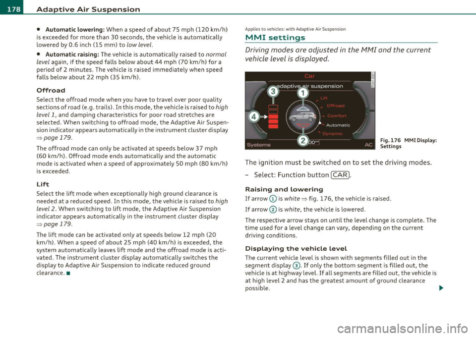
Fig.176 MMI Display:
Settings
The ignition must be switched on to set the driving modes.
- Select: Function button
(CAR].
Raising and lowering
If arrow (Dis white => fig. 176, the vehicle is raised.
If arrow @ is
white, the vehicle is lowered .
The respective arrow stays on until the level change is complete. The
time used for a level change can vary, depending on the current
driving conditions.
Displaying the vehicle level
The current vehicle level is shown with segments filled out in the
segment display ®·
If only the bottom segment is filled out, the
vehicle is at highway level. If all segments are filled out, the vehicle is
at high level 2 and has the greatest amount of ground clearance
possible. .,_