display AUDI Q7 2010 Owner´s Manual
[x] Cancel search | Manufacturer: AUDI, Model Year: 2010, Model line: Q7, Model: AUDI Q7 2010Pages: 390, PDF Size: 93.04 MB
Page 4 of 390
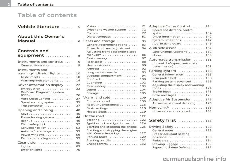
Table of contents
Table of contents
Vehicle literature ..... .
About this Owner's Manual .......... ......... .
Controls and
equipment .............. .
Instruments an d contr ols ... .
Gene ral illus tration ........... .
Instruments and
wa rni ng/indi cator Ligh ts ..... .
Instrumen ts ... ... .......... .
Warning/ indicator ligh ts ..... . .
Driver inform atio n dis pla y ... .
Introduction ...... ...... ... . .
On-Board D iagno stic sy ste m
(OBD) . ..... ....... .......... .
Auto Ch eck Control ........... .
Speed warning system ........ .
Tr ip compu ter ....... ........ .
Opening and closing ......... .
Keys ............ ............ .
Power locki ng sys tem .... .... .
Rear lid .... ..... ............ .
Child safety Lock ............. .
Convenience key ............. .
An ti-thef t alarm sys tem .... .. .
Power w indows .............. .
Panoram ic sliding sunroof ..... .
C lea r vision .. .... ............ .
L igh ts ... .. ........ ......... .
Interior ligh ts ... ... .. ....... .
5
6
8
9
9
1 0
1 0
1 4
22
2 2
2 6
27
35
37
4 0
40
4 4
49 52
53
55
56
59
65
65 7 0 Vi
sion .................... .. .
W iper and washer system
Mi rrors ... ............ ...... .
Digi tal compass ............ .
Sea ts a nd storage ..... ...... .
General recommendations .... .
Power front seat adjus tmen t .. .
A dj usting fron t pa sse nger's se at
ma nually .... ............... .
Seat m emory ......... ....... .
Rear sea ts .... .. .. .......... .
Head res tra in ts ........ ...... .
A rmrest .. .... .............. .
Long ce nter conso le ... ....... .
L uggag e com par tm en t ....... .
Roof rack . .... .... .......... .
Cupho lder .... .............. .
Rear ashtray . ... .. .......... .
Outl et ....... ............. .. .
S torage .................... .
Warm and cold .............. .
Climat e contro l .......... .... .
Rear A ir Condi tioning ......... .
Basi c se tting s ............ ... .
Heated Seats ................ .
On the road ................. .
Steering .. ... ..... ...... .... .
I gn ition lock a nd ign it ion sw itch
S ta rti ng and stopp ing th e e ngin e
S tar ting and s to pping the engine
w ith Conv eni ence key .. ..... .. .
Parking brake ............... .
Starting on h ills .. ... ...... . .
C ruise contro l ............... . 7
1
7 2
7 7
81
83
83
84
86
87
88
90
92
93
94
100
1 02
103
1 04
105
109
109
116
1 18
1 19
1 22
1 22
12 4
125
1 27
129
131
1 32
A dap tive C ruise Contro l ... .... 1 34
Speed and d istance contro l
system .... .................. . 134
Dr iver info rma tion . . . . . . . . . . . . . 14 2
Sy ste m Limitation s ............ 147
Au di braking guard . . . . . . . . . . . . 149
Audi side assist ............ ... 152
L an e Chang e Ass ist ant .. .. ..... 152
No tes .................... .... 159
Automatic transmiss io n 161
tiptroni c® (6-sp ee d au toma tic
t ra nsmiss ion) ........... ... ... 161
Par king system ............. .. 1 68
Ge nera l information . . . . . . . . . . . 168
R ear pa rk assis t . . . . . . . . . . . . . . . 168
Parking sy stem advan ced .... ... 169
Ad justing the display and warn ing
tone s ................ ..... ... 174
Traile r hitch ...... ........ .... 175
E rror messages .............. . 175
Adaptive A ir Suspension ... ... 176
A ir suspens ion and damp ing . . . . 17 6
Homelink ® ............. ... ... 183
Un ive rsal remote control 183
Safety first ............... 188
D riving Safely .............. ... 188
Ge nera l note s ...... ......... .. 188
Proper occupant seati ng
pos itions . . . . . . . . . . . . . . . . . . . . . 190
Pedal area ................ .... 194
Stowing Luggag e .............. 195
R ep o rting Saf ety D efects . . . . . . . 197
Page 8 of 390
About this Owner's Manual
About this Owner's Manual
This owner's manual contains important information, tips, sugges
tions, and warnings for the use of your vehicle.
Make sure that this owner's manual is always located in the veh icle.
This is especia lly important if you allow other people to drive the
vehicle, or if you sell it.
This owner's manual describes the
equipment range specified for
this model at the editorial deadline date. Some of the equipment
described here will only be available at a later date, or only in specific
markets.
Some sections in this owner's manual do not apply to all vehicles. In
that case, the
range of applicability is given at the beginning of the
section, e.g. "Applies to veh icles : w ith parking system advanced". In
addition, optional equ ipment is indicated by an asterisk"*".
Th e detai ls in the
illustrations may be different from those in your
vehicle, and are intended to be viewed as a basic gu ide.
You will find a
table of contents at the beginning of this book, which
displays all topics described in this manua l in order of appearance.
You will find an alphabetical
index at the end of this book.
All
directions , such as "left", "right", "front", "back", are relative to
the direction of travel.
* optional equipment
.,. This section continues on the next page.
a Indicates the end of a section.
® Registered trademarks are identified with a®. If this symbol is
missing, it is no guarantee that the terms can be used freely.
=> &. Cross-reference to a "WARNING!" within a sect ion. For indica
tion with a page number, the corresponding "WARN ING!" can be
found outs ide of the section .
& WARNING
Text with this symbol contains important information on safety
and how to reduce the risk of personal injury or death .
0 Note
Text with this symbol draws your attention to potential sources of
damage to your vehicle.
W For the sake of the environment
Text with this symbol contains information about the environment
and how you can help protect it.
[I) Tips
Text with this symbol contains special tips and other information
about getting the most out of your vehicle and its features. •
Page 13 of 390
If the needle is well in the upper area of the gauge, the coolant
tempe rat ure is too high.
Stop the vehicle , switch the engine off and
allow the engine to cool.
If the warning light comes on again after
driving a short distance, contact an authorized dealer.
& WARNING
• Alway s observe th e warning in=> page 286 , "Engine comp art
ment ", before opening the hood and checking the engine coolant
level.
• Never open the engine hood if you see or hear steam, or if you
s ee engin e coolant dripping from the engine compartment. You
could burn yourself. Let the engine cool off first so that you cannot
hear or see any steam or engine coolant .
0 Note
• Mounting additiona l lights or accessories in fron t of the a ir inlets
reduces the cooling effect of the radiator . At high outside tempera
t ur es o r high engine load, the engine could overheat.
• The front spo iler has bee n des igned to prope rly d istribute the
coo ling air when the vehicle is moving.
If the spoiler is damaged, this
cou ld reduce the coo ling effect and the eng ine could then overheat .
Ask your author ized A udi dealer for assistance .•
Tachometer (engine rev counter)
The tachometer indicat es th e engine RPM (revolutions
per minutes).
Th e ta chomete r@ ::::> page 1 0, fig. 2 is the left of the tw o large clock
type displays.
Th e engine tu rns at a speed
1,000 times the si ng le dig it in the
display, e.g. if the need le is po int ing at the "2 " the engi ne is t urning
at 2,000 RP M.
Controls and equip
ment Safety first
Instruments and warning
/indicator lights
If e ngine RPM drops below 1,500, you s hould dow nsh ift to t he next
lower ge ar. T he re d area at t he e nd of the s cale i ndic ates m aximum
permissible e ngine RPM after the break-in per iod . Before reaching
this area, move the selector lever to posit ion "D (Drive)" or ease yo ur
foot off the accelerator pedal.
0 Note
T he tachome ter needle s houl d not move into the red range. If it does,
then only fo r a very short period of time . You could damage your
e n g in e by driv ing at h igh RPM .
c£> For the sake of the environment
Upshifting early saves fuel a nd reduces e ngine noise. •
Digital clock with date display
Date and time of day can be set in the MM I.
Fig. 3 Instrumen t
cluster with digital
clock
Th e d ate, t ime o f day, and time and date fo rmat c an be se t in the
MMI. You can find o ut more in the MMI manual.
Vehicle care Technical data
Page 14 of 390
Instruments and warning /indicator lights
(I) Tips
• T he dig ita l clock and the odomete r are t urned on for about 30
seconds when the driver's door is opened .
• When the ign ition is turned off, the odometer read ing and the
digital clock with date disp lay can be switc hed on for about
30 se conds by press ing the
[CH ECK! button~ page 13, fig. 5. •
Speedometer with odometer
The speedometer shows you the vehicle speed, and the
odometer shows you how many miles (kilometers) you
have driven .
"' ---------1 ~ .!, ;g
Fig. 4 Instrume nt
clu st e r O dom eter a nd
r e se t bu tton
The odometer and tr ip odometer are located inside the speedometer .
• USA models -Miles
• Canada models -Kilometers
You can sw itch the display from miles to kilometers and vice versa via
t he MM I.
Lower odometer
The lowe r odometer shows the total n umber of m iles ( kilomete rs)
dr iven .
Upper odometer (trip odometer)
The upper odometer shows the total n umber of m iles (k ilometers)
dr iven since you last reset the odometer to zero . You can use th is
odometer when you want to keep track of how many m iles (kilome
ters) you have dr iven for a sing le trip or errand. The last d igit indicates
1/10 of a mile (100 meters) .
You can reset t he t rip odometer to zero by pressi ng t he Rese t bu tto n
~ o.o.
Malfunction message
If there is a malfunction somewhere in the instrument cluster, dEF
w ill appear in the tr ip odomete r and will s tay on . Con tact yo ur autho
r ized Audi dealer to have the problem corrected.
[ i ] Tips
• The d igita l clock and the odometer are turned on for about 30
seconds when the driver 's door is opened .
• When the ignition is turned off, the odometer reading and the
dig it a l cl ock with date d isp lay can be sw itched on for abou t
30 seconds by pressing the [
CHECK! button=> page 13, fig. 5. •
Fuel gauge
The fuel gauge only works when the ignition is on.
When the need le reaches the rese rve mark, the~
page 33 symbol
appea rs in the instrument cluste r display as we ll as the message
Plea se refuel. T here are approximate ly between 2.6 and 3.2 gallons
( 1 0-12 li ters) of fuel left . T hi s message is meant to remind you to
refuel.
Th e to tal tank capa city of yo ur vehicle is liste d in ~ page 363.
Page 15 of 390
0 Note
Never run the tan k comp letely d ry . An irregular s upply of f ue l can
cause engine misfiring and fue l cou ld enter the ex ha ust system . T he
c ata lytic co nve rter co ul d the n overhea t and be damaged .•
[ C HECK ) button
You can per form differen t functions wi th this button.
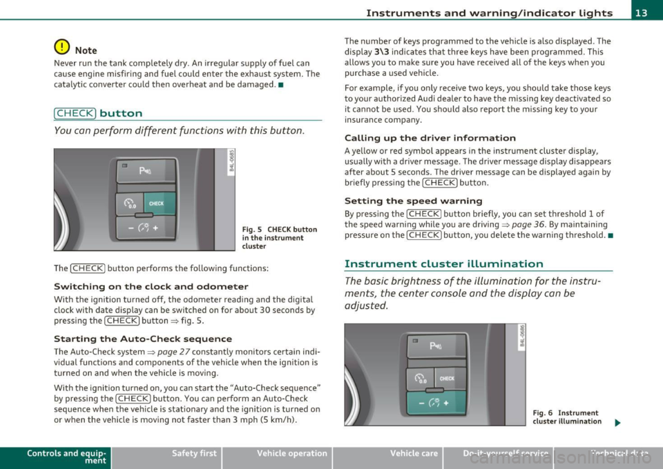
Fig . 5 CHE CK button
i n the in strume nt
clu ste r
Th e [ C H ECK] bu tton perfo rms the fo llowing func tions :
Switching on the clock and odometer
With the ignition tu rned off, the odome ter read ing and the dig ita l
clock with date d isplay can be switched on for abo ut 30 seconds by
pressin g the [
CHECK ] button ~ fig . 5.
Starting the Auto-Check sequence
The Auto-Check system~ page 2 7 constantly monitors ce rtain indi
vidual functions and components of the vehicle when the ignit ion is
tur ned on and w hen the vehicle is movi ng.
With the ignition turned on, yo u can sta rt the "A uto-Check sequence"
by pressing the
!CHECK ] button. You can perform an Auto -Check
sequence whe n the veh icle is st ationa ry a nd the ignition is turned on
or when the vehicle is moving not faster than 3 mph (5 km/h) .
Control s and equ ip
m ent Vehicle OP-eration
Instruments and warning /indicator lights
The nu mber of keys programmed to the vehicle is a lso displayed . The
di splay
3\3 indic ates th at three keys have been programmed . T his
allows you to make sure you have received all of the keys w hen you
purc hase a used ve hicle.
For example, if you o nly receive two keys, yo u sho uld ta ke tho se keys
to your a uthorized Audi dealer to have the missing key deactivated so
i t ca nn ot be used. You sh ould also re port the mis sing key to you r
insurance compa ny.
Calling up the driver information
A ye llow or red symbol appears in the instrument cluster display,
us ua lly w it h a dr ive r mes sage . T he driver message display di sappe ars
after about 5 seco nds. The driver message can be displayed again by
br iefly p ressing t he
[CHECK ] but to n.
Setting the speed warning
By press ing t he I CH ECK] button br iefly, you can set t hreshold 1 of
the speed warning while yo u are driving ~
page 36. By maintaining
pressure on the
I CHECK ] button, you de lete the warning th reshol d.•
Instrument cluster illumination
The basic brig htness of the illumination for the inst ru
ments, the center console and the display can be
a dju sted.
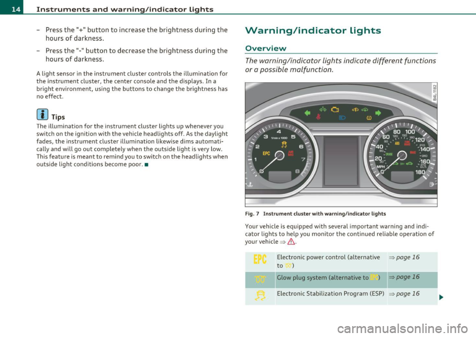
Fig. 6 Instrument
clu ste r illum inat ion .,,_
Vehicle care Do-it-yourselt service iTechnical data
Page 16 of 390
Instruments and warning /indicator lights
- Press the"+" button to increase the brightness during the
hours of darkness.
- Press the"-" button to decrease the brightness during the
hours of dark ness.
A light sensor in the instrument cluster contro ls the illumination for
the instrument cluster, the center console and the displays. In a
br ight env ironment, using the buttons to change the br ightness has
no effect .
[ i ] Tips
The illumination for the instrument cluster lights up whenever you
switch on the ig nition with the vehicle head lights off. As the daylight
fades, the instrument cluster illum inat ion likewise d ims automati
cally and w ill go out completely when the outside light is very low.
Th is feature is meant to remind you to sw itch on the headlights when
outside light conditions become poor. •
Warning/indicator lights
Overview
The warning/indicator lights indicate different functions
or a possible malfunction .
Fig . 7 Instr um ent cluste r w ith warn in g/ indicato r lig hts
Your vehicle is equipped with several important warning and ind i
ca tor lights to he lp you moni to r the continued re liable operat ion of
your vehicle ~& .
Electronic power cont rol (a lternative
~ page 16
to )
Glow plug system (alternative to ) ~ page 16
Elect ronic Stabili zation Prog ram ( ESP) ~ page 16
-
Page 24 of 390
Driver information display
Driver information display
Introduction
General notes
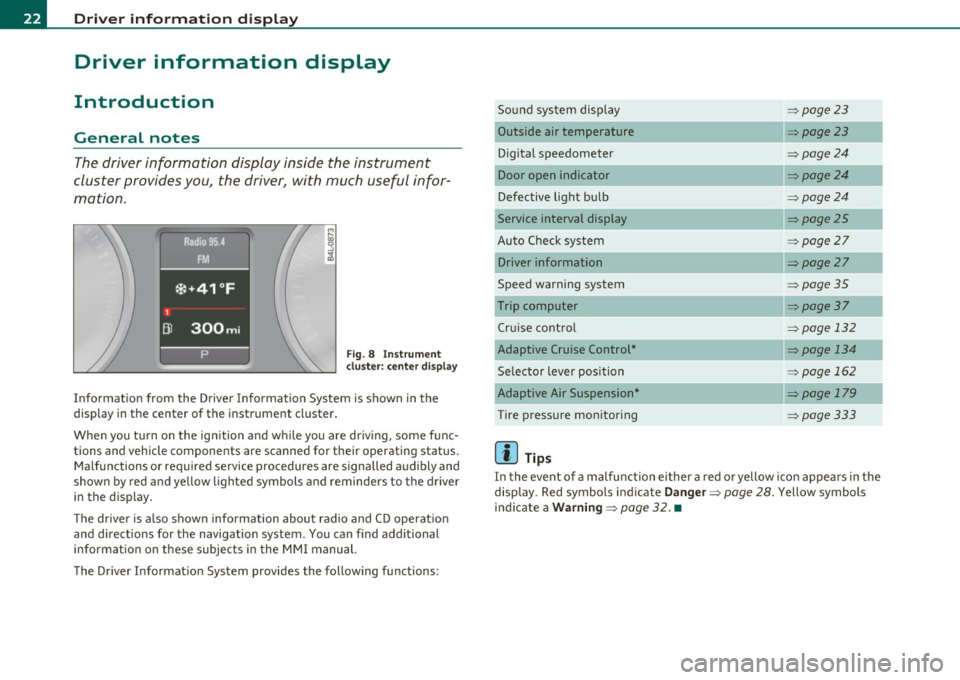
The driver information display inside the instrument
cluster provides you, the driver, with much useful infor
mation .
Fig. 8 Instrument
cl uste r: center display
Informat ion from the Driver Information System is shown in the
display in the center of the instrument cluster.
When you tu rn on the ig nition and while you are driving, some func
tions and vehicle components are scanned for their operating status. Malfunctions or required service procedures are signalled audibly and
shown by red and yellow lighted symbols and reminders to the driver
in the display.
Th e d river is also shown information about radio and CD operat ion
and directions for the navigation system. You can find additional
information on these subjects in the MMI manual.
The Driver Informat ion System provides the following functions: Sound system display
=>
page23
Outside air temperature =>page23
Digital speedometer =>page24
Door open indicator =>page24
Defective light bulb =>page24
Service interval display =>page25
Auto Check system => page27
Driver information =>page27
Speed warning system =>page35
Trip computer => page 37
Cruise control => page 132
Adaptive Cruise Control* => page 134
Selector lever position => page 162
Adaptive Air Suspension* =>page 179
Tire pressure monitoring =>page333
[ i ] Tips
In the event of a malfunction either a red or yellow icon appea rs in the
display. Red symbols indicate
Danger => page 28. Yellow symbols
ind icate a
Warning => page 32. •
Page 25 of 390
Sound system display
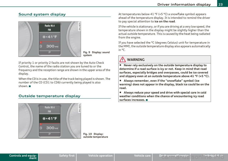
Fig. 9 Di sp lay : sound
s ystem
If prior ity 1 or priority 2 fau lts a re not show n by the A uto Ch eck
Con trol, the name of the ra dio s tat ion you are tuned to or the
frequency and the recept io n range are s hown in the upper area of the
display.
When the C D is in use, the title of t he track be ing p layed is shown. The
number of the CD (CDl to CD6) cu rrent ly being played is also
shown. •
Outside temperature display
Contro ls a nd e quip
m en t
Fig . 10 D ispl ay :
o uts id e tempera ture
Vehicle OP-eration
Driver information display
At temperatures be low 41 °F ( +S °C) a s nowflake symbol appears
a he ad of t he temperature displ ay . It is in tended to remi nd t he driver
to pay special attention to
ice on the road .
If the vehicle is stationary, or if yo u are driving at a very low speed, the
tempe ra ture shown in the d isp lay m igh t be sligh tly higher than the
actua l outside temperat ure. This is cause d by the heat being radiated
fr om the e ng ine.
If you have selected the °C (degrees Ce lsius) un it for temperature in
the MMI, the outs ide tempe rature display a lso appears automatically
in°(.
& WARNING
• Never rely exclusi vely on the outs ide temperature display to
determine if a road surface is icy or not . Keep in mind that road
surfaces, especially br idges and overpasses , could be ice covered
and slippery even at an outside temperature above 41 °F (+S °C ).
• Always remember , even if the "snowflake " symbol (ice
warning ) does not appear in the di splay, black ice could be on the
road .
• Alway s reduce your speed and drive with special care in cold
weather cond itions when the chance of encountering icy road
surfaces increa se s.•
Vehicle care Do-it-yourselt service iTechnical data
Page 26 of 390
Driver information display
Digital speedometer
Fig. 11 Display:
Digita l speedomet er
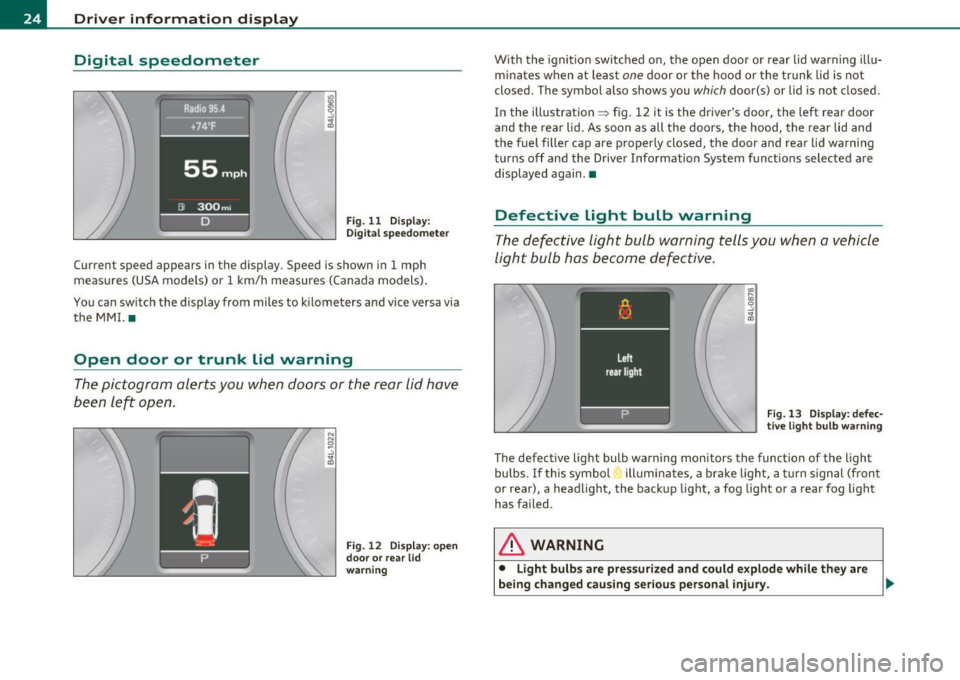
Current speed appears in the display. Speed is shown in 1 mph
measures (USA models) or 1 km/h measures (Canada models) .
You ca n sw itch the display from miles to kilometers and vice versa via
the MMI. •
Open door or trunk lid warning
The pictogram alerts you when doors or the rear lid have
been left open.
Fig. 12 Display: open
d oo r or rear lid
warning
With the ignition switched on, the open door or rear lid warning illu
minates when at least one door or the hood or the trunk lid is not
closed. The symbol also shows you
which door(s) or lid is not closed.
In the illustration ~ fig. 12 it is the driver's door, the left rear door
and the rear lid. As soon as all the doors, the hood, the rear lid and
the fuel filler cap are properly closed, the door and rear lid warning
turns off and the Driver Information System functions selected are
displayed again. •
Defective light bulb warning
The defective light bulb warning tells you when a vehicle
light bulb has become defective .
Fig. 13 Display : defec
tive light bulb warning
The defective light bulb warning monitors the function of the light
bulbs. If this symbol illuminates, a brake light, a turn signal (front
or rear), a headlight, the backup light, a fog light or a rear fog light
has failed .
& WARNING
• Light bulb s are pressurized and could explode while they are
being changed causing serious personal injury. .,._
Page 27 of 390
& WARNING (co ntinued )
• Wo rk with due care when handling the high-volt age section of
gas di scharge (xenon) lights. Failure to do so could result in death
or ser ious injury.
[ i ] Tips
Have the bulb replaced or the connection repaired by your autho rized
Audi Se rvice departmen t.•
Service interval display
The service interval display reminds you when your next
service is due.
Fig . 14 D ispl ay :
Service inte rval disp la y
Th e schedu le for the next oil change or inspection is c alc ul ated auto
matically and displayed accord ingly. The display works in two stages:
Service reminder
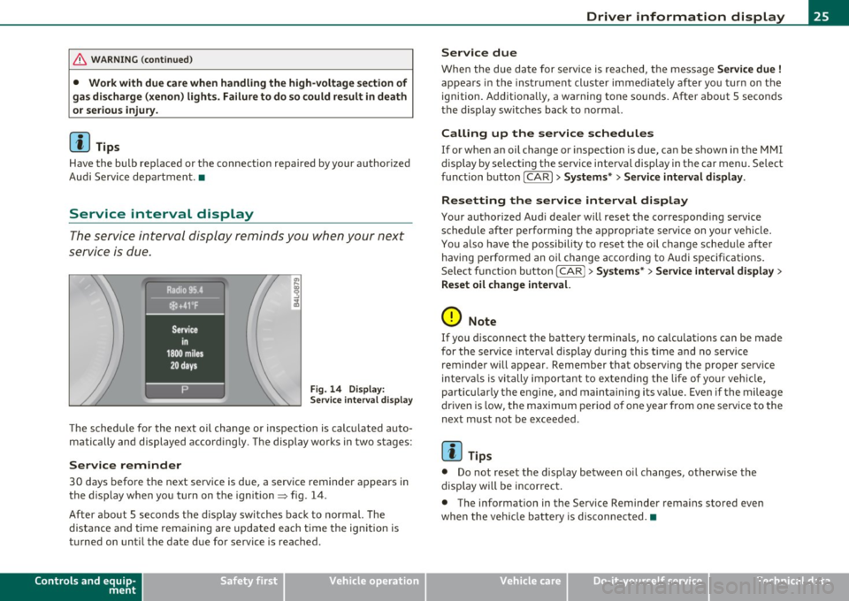
30 days before the next serv ice is due, a serv ice reminder a ppears in
the display when yo u turn on t he ign it ion=> fig. 14 .
After about 5 seconds the d isp lay switches back to normal. The
dis tan ce and time rema ining are updated each t ime t he ig nition is
turned on unti l the date due for service is reac hed .
Controls and equip
ment Safety first
Driver information display
Service due
W
hen the due da te for service is rea ched, t he message Service due !
appea rs in the inst rument cluste r immediately afte r yo u tur n on the
ignition. Additiona lly, a wa rning tone sounds. After about 5 secon ds
the d isp lay sw itches back to no rma l.
Calling up the service schedules
If or when an oil change or inspection is due, can be shown in the MMI
display by se lecting the se rvice interval display in the car menu. Se lect
fu nction button
I CAR ]> Systems *> Service interval display.
Resetting the service interval display
Your authorized Aud i dea ler will reset the correspond ing se rvice
schedule after performing the a ppropriate service on yo ur vehicle .
You a lso have the possibility to reset t he oil c hange sched ule afte r
having performed an o il change acco rding to A udi specifications.
Se lect f unct io n butto n
I CAR j >Systems *> Service interval display >
Reset oil change interval.
0 Note
If you d isconnect the batte ry termina ls, no ca lculations can be made
for the se rvice in terva l display d uring this time and no serv ice
reminder will appear . Remember that observing the proper service
in terv als is vi tally import ant to ex te ndi ng the life of your vehi cle,
particularly the engine, and maintaining its value . Even if the mileage
dr iven is low, the max imum per io d of one year from one serv ice to the
next must not be exceeded.
[I] Tips
• Do not reset the display between oi l changes, otherw ise the
display will be incor rec t.
• The info rmation in the Service Reminder rema ins stored even
when the vehicle ba tte ry is disconnec ted. •
Vehicle care Technical data