display AUDI Q7 2012 Owner´s Manual
[x] Cancel search | Manufacturer: AUDI, Model Year: 2012, Model line: Q7, Model: AUDI Q7 2012Pages: 342, PDF Size: 86.42 MB
Page 222 of 342
220 Intellig ent technol ogy
The vehicle is then stabilized by the forces act
ing on the whee l during braking. If the vehicle
is
oversteering (rear tends to sk id out of the
turn), the brakes are ma inly applied on the
wheel that is on the outside of the curve. In
the case of a vehicle that is
understeering
(tendency to slide out of the curve), the
brakes are applied as needed on the whee l
that is on the ins ide of the curve or addit ional
l y on the o ther wheels. An acoustic s ignal indi
cates when ESC b rake app lication cuts in
¢ A .
The system operates across the entire speed
range in combination with the ABS system
¢ page 223. If the Anti-Lock Brake System
(ABS) malfunctions, the ESC wi ll be out of ac
tion as well .
Activating
When you turn on the engine, ESC w ill auto
mat ica lly be act ivated and will perform a se lf
test. As soon as the test is comp leted, the sys
tem is in normal operating mode.
Offroad mod e
ESC should normally be ope rated in normal
mode because this ensures maximum vehicle
stability. If necessary, you can act ivate the
ESC offroad mode by pressing the but to n
¢ fig . 218 to obtain maximum traction and
braking ability when driving
off paved roads at
l ow speeds. In ESC offroad mode, the indica
tor light
fi illuminates and the message Off
road control Warning! Red uced t ract ion
ap
pears briefly in the display .
The ESC offroad mode can be usefu l in the fo l
low ing except iona l situations when slip or a
h ighly effective differentia l locking function is
desirable . Examples:
- when driving with tire chains,
- when driving in deep snow or on loose
ground,
- when driving on uneven surfaces with the
wheels severe ly unloaded (articulation), and
- when rocking the vehicle loose after it has
become stuck.
When the unusua l situat ion is past, you
should shift back to the normal ESC operating mode by pushing the button again
. The mes
sage
S tabilit y prog ram on then appears brief
l y in the display.
H ill descent control
T he hill descent con trol is swi tched on in ESC
offroad mode . When slowly descending steep
gradients on loose gro und or when the axles
are articulated, hill descent control provides
ass istance by automatically applying the
brakes to keep vehicle speed constant. The ve
hicle is also rendered easier to steer by selec
t ive d istr ibut ion of braking force . H ill descent
control intervenes when:
- the acce lerator pedal is not pressed,
- the vehicle is travelling less than 12 mph
(20 km/h),
- a steep gradient is detected,
- wheel behavior indicates loose ground or
conditions with poor adhesion (e.g . a lso axle
articu lation).
Hill descent con tro l operates both d riving for
ward and in reverse. Active hill descent con
trol is deactivated by pressing the accelerator
pedal unti l the conditions for activation al
ready listed are met again.
A WARNING
- The Electronic Stability Control is never
theless subject to the laws of phys ics. It
is part icu larly important to pay attention
to this fact on wet and slippery roads. It is therefore impo rtant that you a lways
a dapt your d riving to the condit ion of the
road and traffic cond itions. Do not allow
the increased safety provided by the Electron ic Stability Control system to lull
you into accepting additional safety
risks.
- Please be aware that in ESC offroad
mode, particularly on a smooth and s lip
pery road, the wheels may have an in
creased tendency to spin and the vehicle
may break away - danger of skidding!
- Stability is limited in the ESC offroad
mode.
Page 228 of 342
226 Intelligent technology
can result in there being insufficient energy
avai lab le to start the engine .
I ntell igent energy management in your vehi
cle handles the distribution of electrical ener
gy . Starting abi lity is markedly improved and
the life of the battery is extended .
Basically , energy management consists of
battery diagnosis , idling current manage
ment
and dynamic energy management.
Battery diagnosis
Battery diagnosis continuously determines
the state of the battery. Sensors determine
battery volta ge, battery current and battery
temperature. This determines the current
state of charge and the power of the battery.
Idling current management
Idling current management reduces energy
consumption while the vehicle is stand ing.
With the ignition switched off, it contro ls the
energy supply to the various e lectrica l compo
nents. Data from battery diagnosis is consid
ered.
Depending on the battery's state of charge,
individua l consumers are gradually turned off
to prevent excessive discharge of the battery
and thus maintain starting capability.
Dynamic energy management
While the vehicle is being dr iven , dynamic en
e rg y management distributes the energy gen
erated according to the needs of the individu
a l components. It regulates consumption, so
that more ele ctrical energy is not being used
than is being generated and ensures an opti mal state of cha rge for the battery.
{D) Tips
- But even energy management cannot
negate the limits of physics. Consider
that the power and life of a battery are
limited .
- If starting ab ility is threatened, you are
i nformed by a warn ing
c> page 22 7,
Driver notification in the instrument
cluster display .
What you should know
The highest priority is given to maintaining
starting capability .
The battery is seve rely taxed in shor t-distance
driving, in city tra ffic and dur ing the cold time
of year . Abundant electrical energy is re
quired, but only a little is generated . It is also
critical if the engine is not running and e lectri
ca l components are turned on . In this in
stance energy is being consumed but none is
being generated.
It i s in precisely these situations that you will
notice energy management actively regulat
ing the distribution of energy.
Vehicle stands for an extended period
If you do not drive your vehicle over a period
of several days or weeks , e lectr ica l compo
nents are gradually cut back or sw itched off.
T his reduces energy consumption and main
ta ins start ing capability over a longer period .
Take into consideration that when you unlock
your vehicle , some conven ience functions ,
s uc h as the inte rior lights or the power seat
adjustment, may not be available. The con
venience functions will be available again
when you turn on the ignition and start the e ngine .
With the engine turned off
If you listen to the radio, for example, w ith
the engine turned off or use other MMI func
tions, the battery is being discharged .
If starting capability is jeopardized due to en
ergy consumption , the following warning ap
pears in the MMI display:
Please start engine, otherwise system will
switch off in 3 minutes .
The warning indicates that the system will be
turned off automatically after 3 minutes . If
you w ish to continue using the funct ions, you
have to sta rt the eng ine.
1111>
Page 229 of 342
With the engine running
Although electrical energy is generated when
the vehicle is being driven, the battery can be
come discharged. This happens most ly when
litt le energy is being generated and a great
deal consumed and the battery's state of
charge is not optimal.
To bring the energy balance back into equili
brium, consumers which require especia lly
large amounts of energy are temporarily cut
back or switched off. Heating systems in par
ticular requ ire a great deal of energy. If you
notice, for example, that the heated seats* or
the heated rear window are not heating, they h ave been temporar ily cut back or switched
off. These systems will be available again as
soon as the energy ba lance has been restored.
You will also notice that engine idle speed has
been increased slightly. This is normal and not
a cause for concern . By increasing engine idle
speed the additional energy required is gener
ated and the battery is charged .
Driver notification in the instrument
cluster display
If battery power drops into the range where it
can limit the ab ility of the engine to start, th is
is shown in the instrument cluster display
with the following driver message:
(•i Low battery charge: battery will be
charged while driving
This notification reminds you that the starting
capability of the engine may be limited. As
soon as you start driving again, the battery
will be recharged and the notification will go
out.
Driver notification appears and goes out
again
If th is driver notification appears after the ig
nition is turned on or while driving and it goes
out again after a wh ile, the battery has been
adequately recharged.
Intelligent technology 22 7
Driver notification appears and does not
go out again
If this driver notification appears after the ig
nition is turned on or whi le driving and does
not go out again, the battery's state of charge
is not in the optimal range. Starting ab ility is
restricted . Have the battery checked as soon
as possible by an authorized Aud i dealer or
qualified workshop.
•
•
Page 246 of 342
24 4 Cl eaning and protec tio n
8_ WARNING
- Moisture and ice on brakes may affect
braking efficiency¢
page 222, Gen eral
information.
Test the brakes carefu lly
e ach time you wash the veh icle .
- Always read and heed all WARNINGS and
-
other information ¢ page 239.
Body cavity sealing
The body cavity sealing does not need to be
checked .
All body cavities wh ich could be affected by
corrosion have been thoroughly protected at
the factory.
This sealing does not require any inspection or
additional treatment. If any wax should seep
out of the cavity when the ambient tempera
ture is high, it can be removed with a plastic
scraper and a suitable solvent.
8_ WARNING , ~
Solvents can be dangerous .
- Benzine is flammable and toxic . If you
use benzine for removing the wax, keep
sparks, flame and lighted c igarettes
away. Never dump benzine on the
ground, into open streams or down sew
age drains.
- Be sure to observe all safety and env iron
menta l regulations. Follow all instruc
tions on the con tainer .
- Always read and heed all WARN INGS and
other information
¢ page 239 .
Chassis
Have the undercoating checked for damage
from time to time.
The lower body shell of your Audi is also thor
oughly protected against corrosion .
Any damage to the undercoating caused by road hazards should be repa ired promptly .
8_ WARNING
Too much undercoating in the wrong p la
ces can cause a fire.
- Do not apply additional undercoating or
rustp roofing on or near the exhaust
manifold, exhaust pipes, catalytic con
verter or heat shields. While driving, the substance used fo r undercoating could
overheat and cause a fire.
- Always read and heed all WARNINGS and
other info rmation ¢
page 239.
Exhaust tail pipes
Road salt and o ther co rrosive materials w ill
damage the material in the exhaus t tail pipes
i f they a re not cleaned regular ly . Do not clean
the tail pipes with wheel cleaner, paint polish, chrome polish or other abras ive cleaners .
Clean the tail pipes with car care products
that are suitable for sta inless steel.
Your a uthorized Audi dea ler can provide clean
ing products that have been tested and ap
proved for your vehicle .
Care of interior
MMI display
.,. Clean the MM I display wi th a soft clean
cloth and an LC D cleaner .
T he M MI display can be cleaned wit h a profes
s io nal ly availab le " LCD cleane r". The cloth
sho uld be slightly dampened with t he clean
ing fluid to clean the disp lay.
CIT) Note
To avoid sc ratching the M MI display, you
shou ld never clean it dry.
MMI control console
.,. First clean the MMI contro l conso le with a
brush to remove dust from the housing .
.,. Then wipe the MMI control console with a
clean, soft, slightly damp cloth. .,..
Page 257 of 342
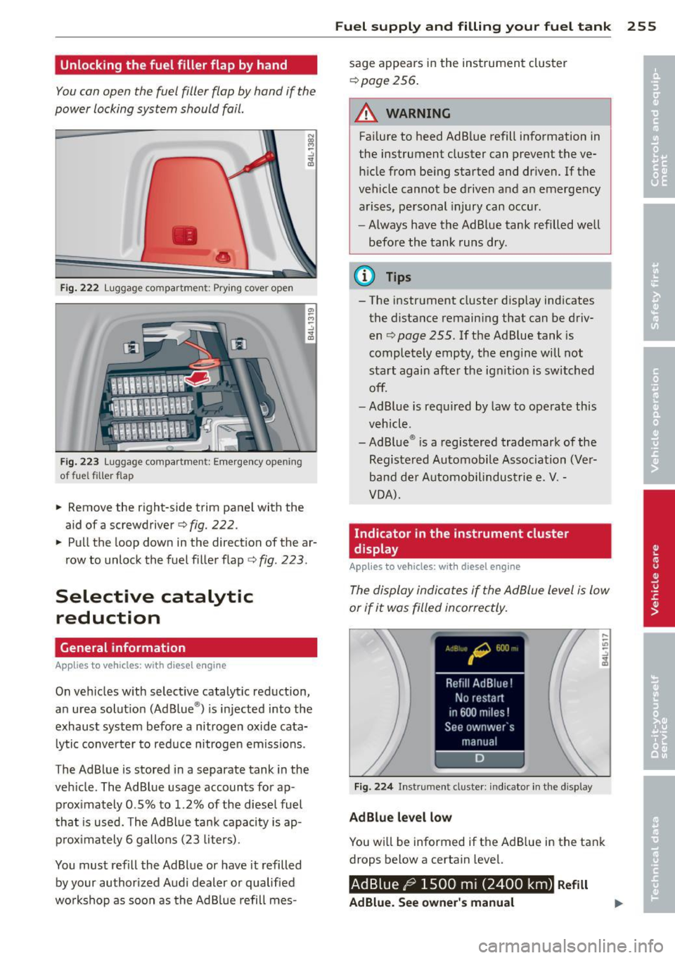
Unlocking the fuel filler flap by hand
You can open the fuel filler flap by hand if the
power locking system should fail.
•
•
Fig . 222 Luggage co mpa rtme nt: Pry ing cover ope n
Fi g. 22 3 Luggage co mpartmen t: Emergency ope ning
of fue l filler flap
.. Remove the right-side trim panel with the
aid ofa screwdriver
¢ fig. 222.
.. Pull the loop down in the direction of the ar
row to unlock the fuel f iller flap ¢
fig. 223 .
Selective catalytic
reduction
General information
App lies to vehicles : with diesel engine
On vehicles w ith select ive catalytic reduction,
an urea solut ion (Ad Blue ®) is injected into the
exhaust system befo re a nitrogen oxide cata
lytic converter to reduce nitrogen em iss ions .
The AdBlue is stored in a separate tank in the
veh icle. The AdBlue usage accounts for ap
p rox imately 0.5% to 1.2% of the diese l fuel
that is used. The Ad Blue tank capaci ty is ap
pr ox ima tely 6 gallons (23 liters) .
You must refill the Ad Blue or have it refilled
by your authorized A udi dealer or qualified
wo rkshop as soon as the Ad Bl ue refill mes-
Fu el suppl y and filli ng your fuel t ank 255
sage appears in the instrument cluster
¢ page 256.
A WARNING
Failure to heed AdBlue refill info rmation in
the instrument cluster can prevent the ve hi cle from be ing started and dr iven. If the
vehicle cannot be driven and a n emerge ncy
a rises, pe rsonal injury can occur .
- Always have the AdBlue tank refilled well
befo re the tank runs dry .
(D Tips
- The instrument cluster d isp lay ind icates
the distance remain ing that can be driv
en ¢
page 255. If the Ad B lue tank is
completely empty, the engine will not
start again afte r the ignit ion is switched
off.
- Ad Blue is req uired by law to operate th is
veh icl e.
- Ad Blue ® is a registered trademark of the
Registe red Automobile Association (Ve r
band de r Automob ilindustrie e .
V. -
VOA) .
Indicator in the instrument cluster
display
Appl ies to vehicles: wit h diesel eng ine
The display indica te s if the Ad Blue level is low
or if it was filled incorrectly.
Fi g. 22 4 Instrument cluste r: in dicator in t he d isp lay
AdBlue level low
You w ill be informed if t he AdB lue in the tank
drops below a certain level.
AdBlue /9 1500 mi (2400 km) Refill
AdBlue. See owner 's manual
Page 258 of 342
256 Fuel supply and filling your fuel tank
This indicator appears when there is on ly
enough Ad B lue left to drive th e distance indi
cated in the driver informat ion system. Please
add Ad B lue.
AdBlue ,0 600 mi (1000 km) Refill
AdBlue! No restart in 600 miles (1000 km )!
See owner 's manual
This indica to r appea rs when there is on ly
enough Ad B lue left to drive the distance ind i
cated in the dr iver information system. Please
add Ad B lue . Otherw ise the eng ine will not
start aga in if you stop it once the distance i n
d icated has been driven .
Refill Ad Blue! No
restart! See owne r's manual
This message appears whe n the AdBl ue ta nk
i s empty . Please add AdBlue. Ot herwise yo u
will not be able to start the engi ne again o nce
you stop it.
When the m inim um AdB lue leve l has been
reached , you must add Ad Bl ue
c:> page 256 .
f.i Filling incorrectly
I f the Ad B lue tank was filled with a diffe rent
f luid than Ad Blue and t he system detec ts that
it is incor re ct, a mess age w ill appe ar.
AdBlue ./' 600 mi (1000 km) AdBlue!
No re start in 600 mile s (1000 km)! See own·
er' s manual
This message appears when it is only poss ible
to drive the distance indicated in the dr iver in
formation system . Dr ive to the nearest qua li
fied work shop to have the malfunc tion re
pai red . O therw ise the engine w ill not start
a ga in if you stop it once the distan ce indicated
has been driven .
AdBlue : sy stem
fault. No restart! See owner's manual
This message appears if the sys tem detects it
was fille d in corre ct ly . Drive immed iate ly to
the nea rest qualified wo rkshop to have t he
mal func tio n repaired. Otherw ise you wi ll not
b e able to s tart the engine ag ain once yo u
stop it. Filling AdBlue
Applies
to vehicles: with diesel engine
A special refill bottle must be used to fill the
AdBlue .
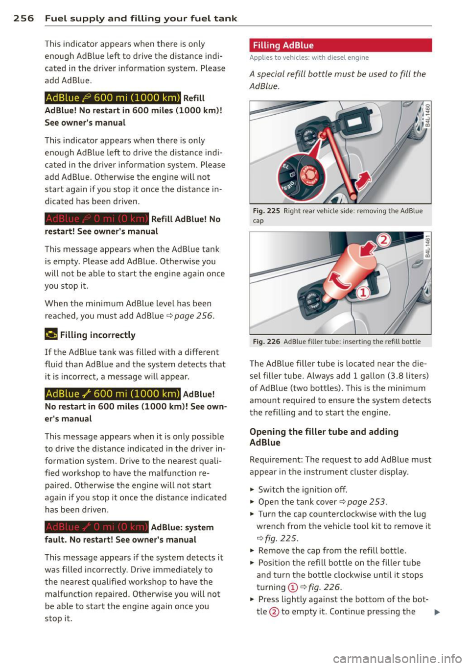
Fig. 22 5 Right rear veh icle side: re m oving th e AdB lue
cap
Fig. 226 AdB lu e fi ller t ube: inser ting the re fill bott le
The Ad Blue filler t ube is located near the d ie
sel filler tube. Always add 1 gallon (3.8 liters)
of Ad Blue (two bott les) . T his is the minimum
amount required to ensu re the system detects
the refill ing and to sta rt the e ngine .
Opening the filler tube and adding
AdBlue
Req uirement: The request to add Ad Blue mus t
appea r in the instrument cluster display.
.,. Switch t he ignit io n off.
.,. Open the tank cover
c:> page 253.
.,. Tur n t he cap counterclockwise with the lug
w rench from the vehicle tool kit to remov e it
<=> fig. 225 .
.,. Remove the c ap fr om the refi ll bottle.
.,. Pos it io n the refill bottle on the filler tube
an d tur n the bo tt le clockwise until it stops
tur ning
(D <=> fig . 22 6.
.,. Press lightly against the bottom of t he bot-
tle @to empty it . Continue pressing the ..,.
Page 259 of 342
bottom of the bottle until it is empty or
until fluid stops f lowing into the tank.
~ Turn the bott le to the left without press ing
on the bottom.
Closing the filler tube
~ Turn the cap clockwise on the filler tube
with the lug wrench until you hear it tighten
completely.
~ Close the tank cover .
After filling
The vehicle must be driven . The system may
take up to two minutes to detect that the
Ad B lue has been filled.
~ If there was no AdBlue left in the tank and a
range of
O mi (0 km ) was displayed in the
instrument cluster, switch the ignition on
for about 15 seconds before starting the en
gine .
.&_ WARNING
Ad Blue can irritate the skin, eyes and res
piratory system. If there is contact with
the fluid, flush immediately with plenty of
water . Consult a physician if necessary .
(D Note
-Only use Ad Blue that conforms to the
standard ISO 22241-1. Do not mix any
additives with the Ad Blue and do not di
lute it with water .
- Ad Blue is not a diesel additive. Do not
add it to the diesel tank. If Ad Blue is
mixed w ith diesel fuel, it can lead to
damage to the eng ine and the Ad Blue
tank system . The Limited New Vehicle
Warranty does not cover such damage.
- AdBlue attacks surfaces such as painted
vehicle components, plast ic and carpet.
Remove the fluid as quick ly as possible
with a damp cloth and plenty of cold wa
ter . If the AdBlue has already crystal
lized, use warm water and a sponge.
AdBlue residue that is not removed w ill
crystall ize and can damage the affected
surface .
Fuel supply and filling your fuel tank 257
-Do not store the refill bottle in the vehi
cle . If it leaks, the escaping Ad Blue could
damage the vehicle interior.
- Do not allow Ad Blue to come into con
tact with clothing . If there is contact
with the fluid, flush immediate ly with
plenty of water .
(1) Tips
-Yo u can obtain refill bottles from any au
thorized Audi dealer or other qualified
workshop .
- Follow the Ad Blue manufacturer's in
struct ions for usage and storage. •
•
Page 295 of 342

TPMS malfunction indicator is combined with
the low tire pressure tellta le . When the sys·
tern detects a malfunction, the telltale will
flash for approximately one minute and then
remain continuously illuminated. This se·
quence will continue upon subsequent vehicle
start-ups as long as the malfunction ex ists .
When the malfunc tion indicator is illuminat·
ed, the system may not be able to detect or
signal low tire pressure as intended. TPMS
malfunct ions may occur for a variety of rea·
sons, including the installation of replace·
mentor alternate tires or wheels on the vehi·
cle that prevent the TPMS from functioning
properly. Always check the TPMS malfunction
telltale after replacing one or more tires or
wheels on your vehicle to ensure that the re
p lacement or alternate tires and wheels allow
the TPMS to continue to function properly.
Tire pressure indicator appears
The tire pressure indicator in the instrument
cluster informs you if the tire pressure is too
low or if there is a system malfunction.
-
-
;g
Fig. 242 Display: underinflat io n warning
Fig. 243 Display: Syste m ma lfunct io n
Using the ABS sensors , the tire pressure moni·
toring system compares the tire tread circum·
Tires and wheels 293
ference and vibration characteristics of the in
dividual tires. If the pressure decreases in one
or more tires, this is indicated in the instru
ment cluster with a warning symbol
[I] and a
message
c;, fig. 242 . The driver message in the
display goes out after S seconds . The driver
message can be displayed again by pressing
the
ICHECKI button . If only one tire is affect·
ed, the disp lay wi ll indicate its posit ion.
The tire pressure monitoring must be reset via
MMI each time the pressures are adjusted (e.
g. when switching between part ial and fu ll
load pressu re) o r after changing or replacing a
tire on your vehicle
c;, page 294. You can find
the recommended tire pressures for your vehi ·
cle on the label on the driver's door pillar
c;,page 278.
Tire tread circumference and vibration charac·
teristics can change and cause a tire pressure
warning if:
- the tire pressure in one or more tires is too
low,
- the tir e has structural damage ,
- the tir e pressure was changed, wheels rotat-
ed or replaced but the TPMS was not reset
c;,page294 .
Warning symbols
[I] loss of pressure in at least one tire c;, .&, .
Check the tire or tires and replace or repair if
necessary . The indicator light
[I] in the instru·
ment cluster also illum inates
c;, page 14.
Check/correct the pressures of all four tires
and reset TPMS via MMI.
IIQ§S, (Tir e Pressure Monitoring System) Tire
pressure! System malfunction . If llQ§f:1 ap·
pears after switching the ignition on or while
driv ing
c;, fig. 243 and the indicator light [I] in
the instr ument cluster blinks for approxi
mately one minute and then stays on, there is
a system malfunction . See your authorized
Audi dealer as soon as possible.
Page 296 of 342

29 4 T ire s and wheel s
,8. WARNING
-If the t ire pressure indicator appears in
the instrument cluster display, one or
more of your tires is s ignificantly under
inflated. Reduce your speed immediately
and avoid any hard steering or bra king
maneuvers. Stop as soon as possible and
check the tires and their pressures. In
flate the tire pressure to the proper pres sure as indicated on the vehicle 's tire
pressure label
c> page 2 78. Driving on a
significantly under-inflated tire causes
the tire to overheat and can lead to tire
failure. Under-inflation also is likely to impair the vehicle's handling and stop
ping ab ility.
- The driver is responsible for ma inta ining
the correct tire pressures. You must check the t ire pressures regularly.
- Under certain cond itions (such as a spor
ty driving style, winter condit ions or un
paved roads), the pressure mon itor ind i
cator may be de layed.
- Ask your author ized Audi dealer if run
flat tires may be used on your veh icle.
Your vehicle registrat ion becomes inval id
if you use these tires when not permit
ted. Damage to your vehicle or accidents
cou ld also resu lt.
(D Tips
- The tire pressure monitoring system
stops working when there is an ESC/ABS
malfunction.
- Using snow chains may result in a system
malfunction.
- The tire pressure monitoring system on
you r A udi was ca lib rated using tires with
the "AO" or "RO" identification. We rec
ommend using these tires .
Reset tire pressure monitoring system
If the tire pressure is adjusted, wheels are ro
tated or changed, the TPMS must be reset via
MMI .
.. Turn on the ignition. ..
Select: Function b utton
I CAR !> Control but
ton
S ys tem s* > Tire p re ss ure mo nitoring >
Sto re no w. Or
.. Select: Function button
I CAR !> Control but
ton
Ca r systems * > Servi cing & checks >
Tire pre ss ure mon itoring > Stor e tire pr es
s ure s.
(D Tips
Before resetting the TPMS, the current
pressures of all four tires must correspond
to the specified values. Adjust the tire pressure and reset the pressure in the t ire
pressure monitoring system acco rding to
the load you are car ry ing
.:>page 278.
Page 307 of 342

Fuse s and bulb s 305
Right cockpit fuse assignment
Fig . 258 Right cockp it: f use pane l w ith plastic clip
No. Con sumer Amps No. Consumer Amps
Fu se pa nel@ (bla ck )
6 Automatic transmission
5/20
1 Heated rear seats
7
E lectronic Stability Control
5
2 Telephone, cell phone package (ESC)
--Shift gate automatic transmis-
Front seat hating/seat ventila-
8 5
3 30/15
tion (right) sion
Electron ic Stab ility Control 9 Parking system
5
4 (ESC) 20
10 Airbag
5
5 Door control module (right side
15 11
Heated rear seats
5
of vehicle) 12 Air-conditioning 5
6 Rear electrical outlets 25 Fuse panel© (red )
7
Lumbar support passenger's
10 1 Instrument cluster
seat 2 Rearview camera
8 Ciga
rette lighter front 20
3 CD player, DVD drive 5
9 Front electrical outlets
25 4 MMI Display 5
10 A/C controls 10
5 Automatic transmission
11 Cooler
15 Panoramic sliding sunroof seg-
7 20
12 Inte
lligent power module pas-
15 ment 1
senger Panoramic sliding sunroof seg-
Fuse panel B (brown ) 8 ment2 20
1 Headlight e
lectronic system
10 Panoramic sliding sunroof sun-
9 20
(right side of veh icle)
blind
Ride height adjustment 5
Window regulators (right side
Telephone package 5 11
of vehicle) 35
4 12 Rear air-condi
tioning contro ls 10
5 Electronic
Stability Cont rol
5
(ESC)