AUDI Q7 2014 Owner´s Manual
Manufacturer: AUDI, Model Year: 2014, Model line: Q7, Model: AUDI Q7 2014Pages: 340, PDF Size: 85.02 MB
Page 21 of 340
Instruments and warning/indicator lights 19
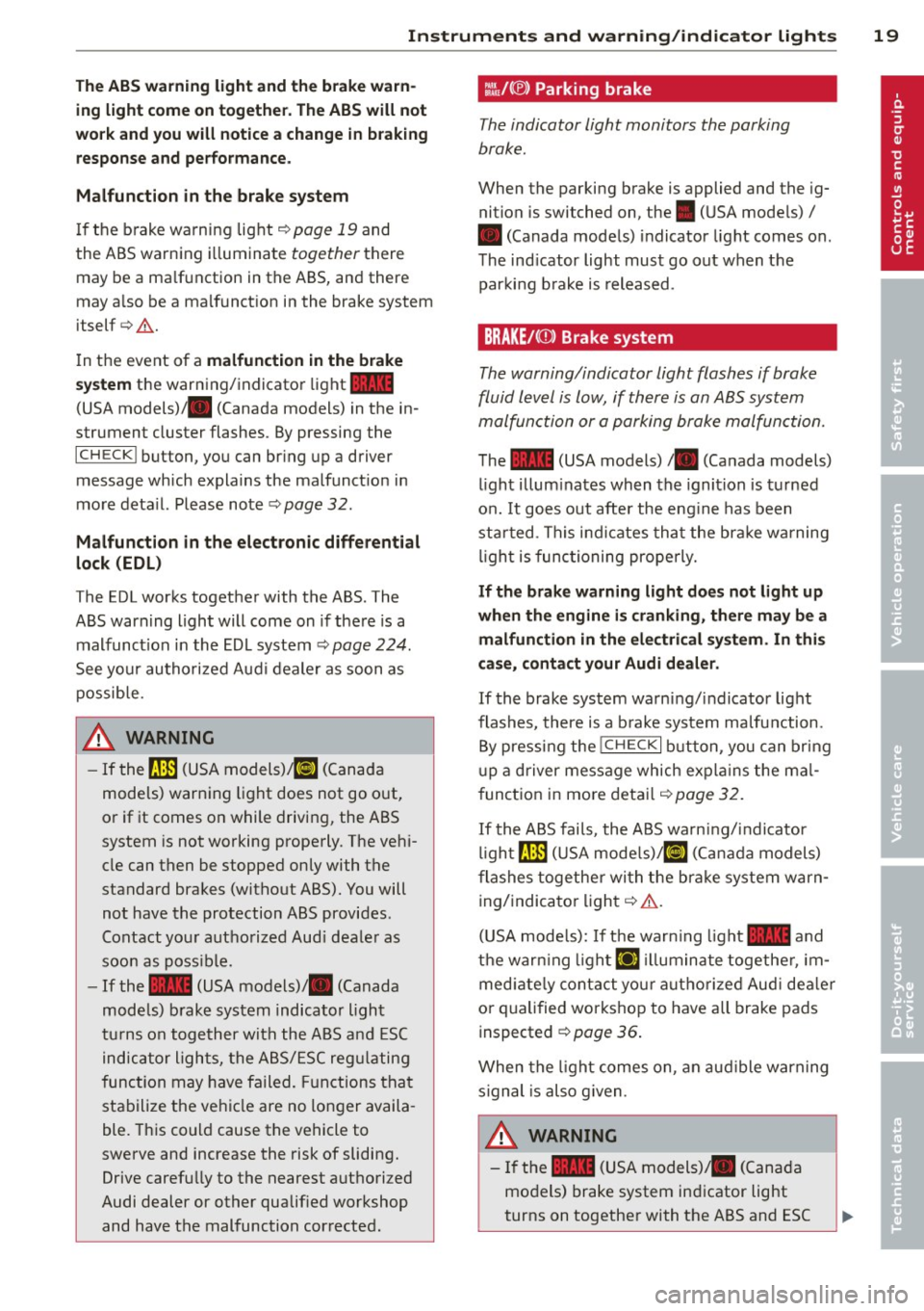
The ABS warning light and the brake warn ing light come on together. The ABS will not
work and you will notice a change in braking response and performance.
Malfunction in the brake system
If the brake warning light <=>page 19 and
the ABS warning illuminate
together there
may be a malfunction in the ABS, and there
may also be a malfunction in the brake system
itself <=>,&. .
In the event of a
malfunction in the brake
system
the warning/indicator light 1111
(USA models);III (Canada models) in the in
strument cluster flashes. By pressing the
ICHECKI button, you can bring up a driver
message which explains the malfunction in
more detail. Please note
<=>pag e 32.
Malfunction in the electronic differential
lock (EDL)
The EDL works together with the ABS. The
ABS warning light will come on if there is a
malfunction in the EDL system
<=> page 224.
See your authorized Audi dealer as soon as
possible.
.&, WARNING
-
- If the f!B (USA models);tlJ (Canada
models) warning light does not go out,
or if it comes on while driving, the ABS
system is not working properly. The vehi
cle can then be stopped only with the
standard brakes (without ABS). You will
not have the protection ABS provides.
Contact your authorized Audi dealer as
soon as possible.
- If the
1111 (USA models)/ . (Canada
models) brake system indicator light
turns on together with the ABS and ESC
indicator lights, the ABS/ESC regulating
function may have failed. Functions that
stabilize the vehicle are no longer availa
ble. This could cause the vehicle to
swerve and increase the risk of sliding.
Drive carefully to the nearest authorized
Audi dealer or other qualified workshop
and have the malfunction corrected.
:l~ /(® ) Parking brake
The indicator light monitors the parking
brake.
When the parking brake is applied and the ig
nition is switched on, the. (USA models) /
• (Canada models) indicator light comes on.
The indicator light must go out when the
parking brake is released.
BRAKE/CCDl Brake system
The warning/indicator light flashes if brake
fluid level is low, if there is an
ABS system
ma/function or a parking brake ma/function.
The 1111 (USA models)/ . (Canada models)
light illuminates when the ignition is turned
on.
It goes out after the engine has been
started . This indicates that the brake warning
light is functioning properly.
If the brake warning light does not light up
when the engine is cranking, there may be a malfunction in the electrical system. In this
case, contact your Audi dealer.
If the brake system warning/indicator light
flashes, there is a brake system malfunction .
By pressing the
I CH ECK i button , you can bring
up a driver message which explains the mal
function in more detail
<=>page 32.
If the ABS fails, the ABS warning/indicator
light~ (USA
models)/KCJ (Canada models)
flashes together with the brake system warn
ing/indicator light<=>,&. .
(USA models): If the warning light
1111 and
the warning light
El illuminate together , im
mediately contact your authorized Audi dealer
or qualified workshop to have all brake pads
inspected ¢
page 36.
When the light comes on, an audible warning
signal is also given .
.&, WARNING ~ ~
-If the 1111 (USA models) ;III (Canada
models) brake system indicator light
turns on together with the ABS and ESC
Page 22 of 340
20 Instrum ent s a nd w arn in g/i ndic ato r light s
indicator lights, the ABS/ESC regu lating
function may have failed. Functions that
stabilize the vehicle are no longer availa ble . This could cause the vehicle to
swerve and increase the risk of sliding.
Drive carefu lly to the nearest authorized
Audi dealer or other qualified workshop and have the malfunction corrected.
- If the brake warning/indicator light does
not go out afte r a few seconds and the
par king brake is released, or ligh ts up
wh ile you are driving, the fluid level in
the brake fluid reservoir is too low. If you believe that it is safe to do so, proceed
immediately at low speed to the nearest
authorized Audi dealer or qualified repair
facility and have the brake system in
spected.
- Always keep in m ind that after several
brake applicat ions, you will need greater
pressure on the b rake pedal to stop your
vehicle . Do not re ly on stra ined brakes to
respond w ith maximum stopp ing power
in cri tic al situations. You must a llow for
increased bra king distances. The extra
distance used up by fad ing brakes could
lead to an accident.
Page 23 of 340

Driver information
display
Introduction
General notes
The driver information display inside the in
strument cluster provides you, the driver ,
with much useful information .
Fig. 9 In st ru men t cl uster: ce nte r dis p lay
Info rmation from the Drive r Information Sys
tem is shown in the display in the center of
t he instrument cl uster .
When you turn on the ignition and while you
are driving, some functions and vehicle com ponents are scanned fo r their operating sta
t us. Malfunc tions or required service proce
dures are signal led aud ibly and shown by red
and yellow lighted symbols and rem inders to
the dr iver in the display.
T he driver i s also shown information abou t ra
d io and CD operation and directions for the
nav igation system . You can f ind additional in
formation on these subjects in the MMI man
ua l.
The Driver Information System prov ides the
following functions:
Sound system disp lay ¢
page 21
Outside air temperature ¢page 22
Digital speedometer ¢
page 22
Door open indicator ¢page 22
D efective light b ulb ¢
poge23
Serv ice i nte rval display ¢page 23
Auto Check system ¢
page 30
Driver information ¢
page 30
Driver inform ation di spl ay 21
Speed warning system ¢page28
T rip computer ¢
page24
Cruise con trol ¢page 111
Adapt ive cruise control* ¢
page 113
Selector lever pos ition ¢page 137
Adapt ive Air Suspension * i=>
page 158
Tire pressure monitoring ¢page 291
(D Tips
In the event of a malfunction either a red
or yellow icon appears in the display . Red
symbols indicate
Dang er ¢ page 31 . Yel
l ow symbo ls indicate a
Warning
¢ page 34.
Sound system display
Fig. 10 D isp lay: so un d syste m
If priority 1 or pr iority 2 faults are not shown
by the Auto Check Control, the name of the ra
dio station you are tuned to or t he frequency
and the recept ion range are shown in the up
per area of the d isplay.
When the CD is in use, the tit le of the track
being played is shown . T he number of the CD
(CDI to CD6) cur rently be ing played is also
shown.
Page 24 of 340
22 Driver in formation d ispl ay
Outside temperature display
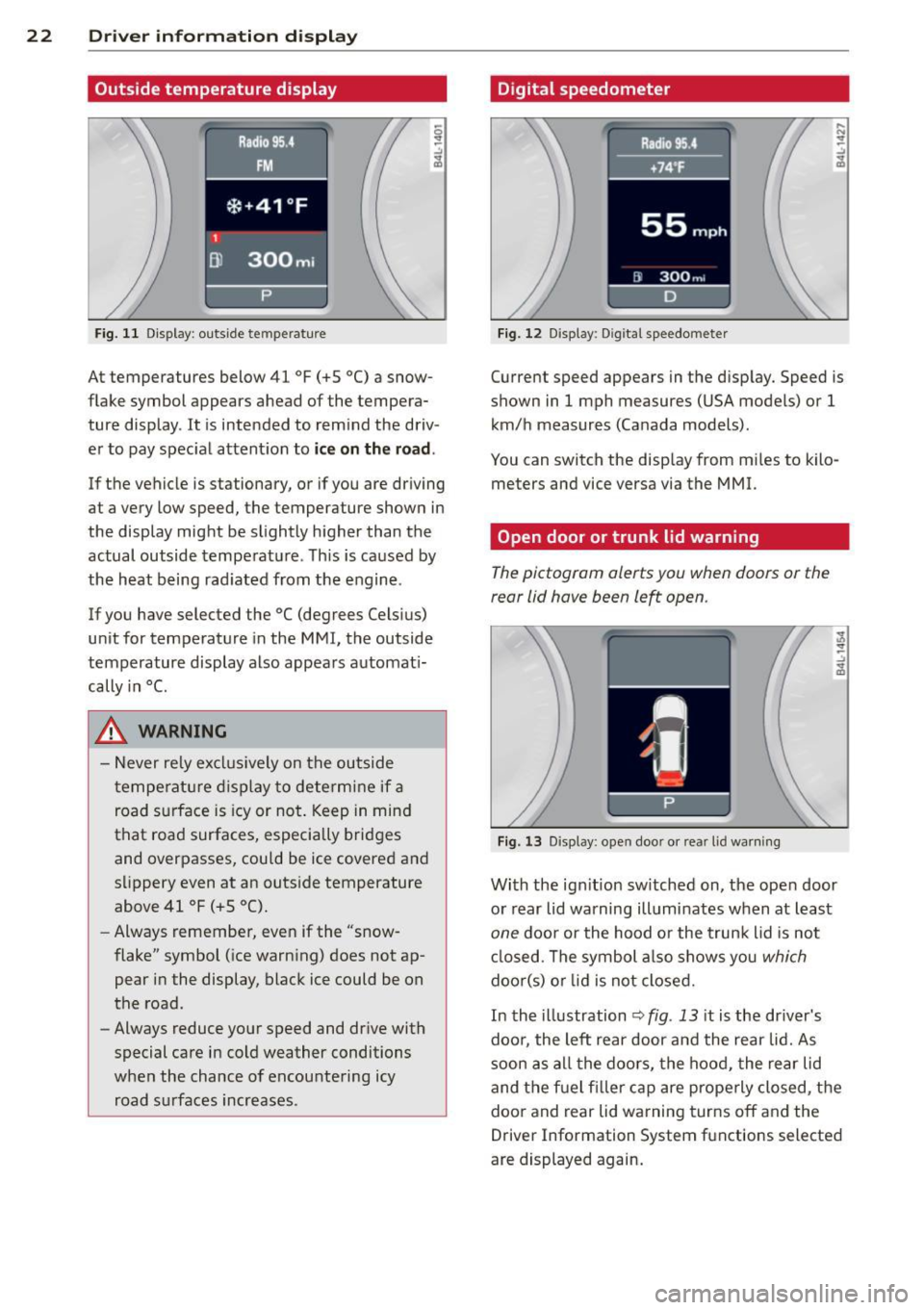
Fig. 11 Display : outside temperature
At temperatures below 41 °F (+S °C) a snow
flake symbol appears ahead of the tempera
ture display . It is intended to remind the driv
er to pay spec ial attent ion to
ic e on the roa d.
If the vehicle is stationary, or if you are driving
at a very low speed, the temperature shown in
the display might be slightly higher than the
actual outside temperature . Th is is caused by
the heat being rad iated from the engine .
If you have selected the °C (degrees Celsius)
unit for temperature in the MMI, the outside
temperature display also appears automat i
cally in
°C.
A WARNING
- Never rely excl usively on the outside
temperatu re d isplay to determine if a
road surface is icy or not . Keep in mind
that road surfaces, especially bridges
and overpasses, could be ice covered and
s li ppery even at an outs ide temperature
above 41 °F (+ S °C).
- Always remember, even if the "snow
flake" symbol (ice warn ing) does not ap
pear in the display, black ice could be on
the road.
- Always reduce your speed and dr ive with
special care in cold weather conditions
when the chance of encountering icy road s urfaces increases .
Digital speedometer
Fig. 12 Display: Digi tal speedometer
Current speed appears in the disp lay. Speed is
shown in 1 mph measures (USA models) or 1
km/h measures (Canada models) .
You can switch the disp lay from m iles to kilo
meters and vice versa via the MMI.
Open door or trunk lid warning
The pictogram alerts you when doors or the
rear lid have been left open .
Fig. 13 Display: open doo r or rea r lid wa rning
With the ign it ion sw itched on, the ope n door
or rear lid warning illuminates when at least
one door or the hood or the trunk lid is not
cl osed . The symbol a lso shows you
which
doo r(s) o r lid is not closed.
In the illustration
~ fig . 13 it is the dr iver's
doo r, the left rear door and the rear lid. As
soon as all the doors, the hood, the rear lid
and the f uel filler cap are prope rly closed, the
door and rear lid warning turns off and the
Driver Information System functions selected
are displayed again.
Page 25 of 340

Defective light bulb warning
The defective light bulb warning tells you
when a vehicle light bulb has become defec
tive.
Fig . 14 D isplay : defective lig ht bu lb warn ing
The defective light bu lb warning monitors the
function of the light bulbs . If th is symbol
I
illuminates, a brake light, a turn signal (front
or rear), a headlight, the backup light, a fog
light or a rear fog light has failed.
A WARNING
- light bu lbs are pressurized and could ex
plode while they are being changed caus
ing serious personal injury.
- Work with due care when handling the
high-voltage section of gas discharge
(xenon) lights. Fa ilure to do so could re
s u lt in dea th o r se rious injury.
(D Tips
Have the bulb replaced or the connection
repa ired by you r autho rized Aud i Service
department.
Dri ver inform ation di spl ay 23
Service interval display
The service interval display reminds you when
your next service is due .
Fig . 1 5 Display: Serv ice interva l d isplay
T he schedule for the nex t oi l change or inspec
tion is ca lculated automatica lly and disp layed
accordingly. The disp lay works in two stages:
Service reminder
30 days before t he next service is due, a serv
ice reminde r appea rs in the display whe n you
turn on the ignition
~fig. 15.
After about 5 seconds the display switches
back to norma l. The distance and time re
mai ning are updated each time the ignit ion is
turned on unt il t he da te d ue for se rv ice is
reached.
Service due
When the due date fo r se rvice is reached, the
mes sage
Se rv ice due! appears in the instr u
ment cluster immed iate ly after yo u tur n on
the ignit ion. Addit iona lly, a warning tone
sounds. After about 5 seconds the disp lay
switches back to normal.
Calling up the service schedules
If or when an oil change o r inspection is due,
can be shown in the MMI display by selecting
the service in terval d isplay in the car menu .
Se lect
I CAR I funct io n button > Sy stem s* con
trol button
> S ervice inte rval display or I CAR !
function button > Car sy stem s* contro l but -
ton
> Servicing & chec ks > Service in te rva ls. ..,_
Page 26 of 340

24 Driver information d isplay
Re setting the service interval display
Your au thor ized A udi dealer w ill reset the cor
responding service sched ule after performing
the app rop riate service on yo ur vehicle . Yo u
a lso have the possibility to reset the oil
change sched ule after having performed an
oil c hange according to Audi specifications.
Select
I CAR I function button > Systems * con
trol button
> Service int erva l display > Re set
oil change interval
or ! CARI function button >
Car systems* control button > S ervicing &
check s > Service interval s > Reset oil change
interval.
(D Note
If you disconnect the b attery termi nals, no
c a lcu lations can be m ade for the servi ce
in terva l display during this time and no
service rem inder w ill appear . Remembe r
that obse rv in g the prope r serv ice interva ls
is vita lly im portant to extend ing the life o f
y o ur veh icle , part icu larly the eng ine, and
maintaining its va lue . Do not exceed the
time int erval fo r th e next se rv ice, even if
the vehicle mileage is low .
@ Tips
-Do not reset the display between oil
changes, otherw ise the display will be in
correct.
- The informati on in the Servic e Reminder
r ema ins sto red even when the vehicle
batte ry is discon necte d.
Trip computer
Introduction
The trip computer gives you information on
current and average fuel mileage, average
speed, fuel range and driving time.
Fig. 16 T rip comp ute r di sp lay : Average f ue l m il eage
T he following dr iving inform ation is con tinu
o usly evalua ted by the trip computer and can
b e displayed sequentially in the instrument
cluster disp lay.
Fuel range
T he es tim ated cru is ing r ange in miles ( km)
appea rs in the display. T his tells you how far
yo ur vehicle will be ab le to travel on the c ur
rent ta nk of f uel a nd with the same driving
sty le. The display changes in increments of 6
miles (10 km).
T he cruising range is calculated based o n the
fuel consum ptio n for the last 18 miles
(30 km). I f you drive conservative ly, the cr uis
i ng range w ill increase.
Average fuel mileage
The aver age f ue l economy in MPG ( l/1 00 km)
s ince you last cleared the memo ry appears in
t hi s disp lay . You can use this display to ad just
yo ur driv ing technique to achieve a desired
mileage.
Current fuel mileage
T he ins tan taneous fuel consum ption in m iles
per gallon ( l/100 km) is shown in this disp lay.
You can use this display to adjust your driving
technique to achieve a desired m ileage .
Ill-
Page 27 of 340

Fue l consumption is reca lculated at interva ls
of 33 yards (30 meters). When the vehicle is
stationary, the most recent fue l consumption
is displayed .
Average speed
The average speed in mph (km/h) since the
l ast time the disp lay was reset appears in the
display .
Elapsed time
The length of time that you have been driving
since you last reset the memory appears in
this display.
Distance
The distance that has been covered since the
l ast time the memory was cleared appears in
the disp lay.
(D Tips
- Fuel consumptions (ave rage and cur
rent), range and speed are displayed in
metric units on Canadian models.
-All stored va lues w ill be lost if the veh i
cle battery is disconnected .
Memories
The trip computer is equipped with two fully
automatic memories as well as an efficiency
program".
Fig. 17 Trip computer d isplay: memo ry level 1
You can switch between the trip computer 1
and 2 and the efficiency program* by pressing
the
! RESET I button @¢ page 25, fig. 18.
You can tell which memo ry level is cur rently
active by the number or the sign in the display
Driver information display 25
¢ fig. 17. The data from the single-trip mem
ory (memory level 1) is being displayed if a
D
appears in the display . If a fJ is shown, then
the data from the total-trip memory is being
displayed (memory level 2). The fuel pump nozzle
iii indicates the efficiency program*
¢page 26.
Single-trip memory (Trip computer 1)
The single-trip memory stores the trip infor
mation from the time the ignition is turned on
until it is turned off. If the trip is continued
within 2 hours from the time the ignition was
turned off, the new data will be included in
the calculat ion of the current trip informa
tion. If the trip is interrupted for
more than 2
hours
the memory is reset automatically.
Total-trip memory (Trip computer 2)
Unlike the single -trip memory, the total -trip
memory is not reset automat ical ly. This per
mits you to evaluate your driv ing data for the
entire period between manua l resets.
Efficiency program*
The efficiency program can help you to use
less fuel ¢
page 26.
Operation
The trip computer is controlled by two
switches on the windshield wiper lever .
Fig. 18 Windsh ield wiper lever : contro ls for the t rip
computer
.. To display the trip computer memory levels,
press the
I RESET ! button®¢ fig. 18 re
peatedly until the desired memory level is
shown in the display . .,.
Page 28 of 340
26 Driver in formation d isplay
• To d isplay trip information within a memory
l evel, press the top or bottom part of the
function selection switch
@ .
The trip computer wi ll not operate unless the
ignition is on. When you turn on the ignition,
the function that was in use when you last
turned the ignit ion off will be d isp layed.
I n addition to information on the trip comput
e r (trip computer 1, 2 and efficiency pro
gram*), the digital speedometer and informa
tion regard ing the nav igat ion system* can al
so be displayed. To switc h the display between
the different information, tap the
I RES ET I but
ton @ briefly .
Setting value s to zer o
To erase the single or total trip comp uter va l
ues, se lect the des ired funct ion and press and
hold the
I RESET ! button@ for at least one
second . You can also erase* the values with
the MMI
¢ page 26 .
All values currently displayed in the efficiency
program* are a lso erased with the s ingle tr ip
computer .
(D Tips
All stored values will be lost if the vehicle
battery is disconnected.
MMI settings
Basic settings for the trip computer can be
made in the MMI.
• Se lect : I CAR ! function button > Systems *
control button > Instrument cluster > On·
board computer 1 or On-boa rd computer 2 .
The values i n the single -t rip or the total -trip
memory can a ll be reset to zero at the same
time under
Reset in the menu .
I n addition, you can de termine what informa
tion from the trip computer sho uld be shown
in the instrument cluster display. If one of the
p ieces of dr iver information is turned
Off , that
driver information w ill not be shown in the
d isplay. The information will con tinue to be ca
lculated by the tr ip comp ute r and can be
turned back
On at any time .
(D Tips
- This function is not available on all
vehicles .
- T he d riving info rm ation in the eff ic iency
program * is also reset to zero with the
sing le-trip memory.
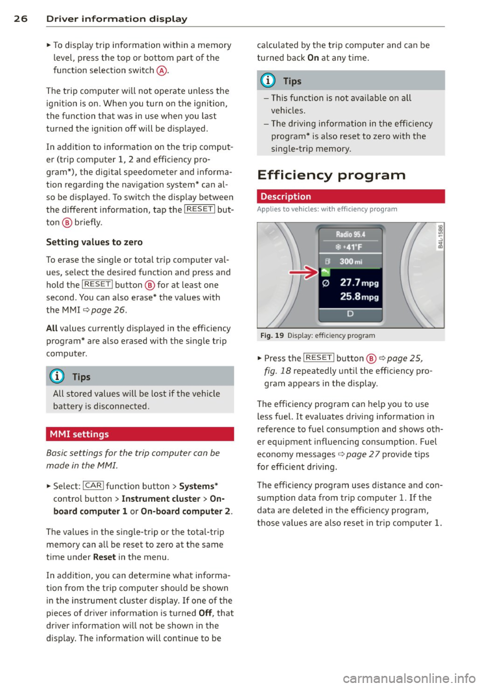
Efficiency program
Description
Applies to vehicles: with efficiency program
Fig. 1 9 Display: eff icie ncy pro gram
• Press the I RESE T! button @¢ page 25 ,
fig . 18
repeatedly unt il the effic iency pro
gram appears i n the display .
T he efficiency program ca n he lp you to use
l ess fuel. It evaluates driving info rmation in
reference to fuel consumption and shows ot h
er equipment influencing consumption. Fuel
economy messages
¢ page 27 provide t ips
for effic ient d riving.
The efficiency program uses distance and con
sumption data from trip computer
l. If the
data are deleted in the efficiency program,
those values a re also reset in tr ip comp ute r
l.
Page 29 of 340
Other equipment
Applies to vehicles: with efficiency program
Fig. 20 D isplay : ot her equipment
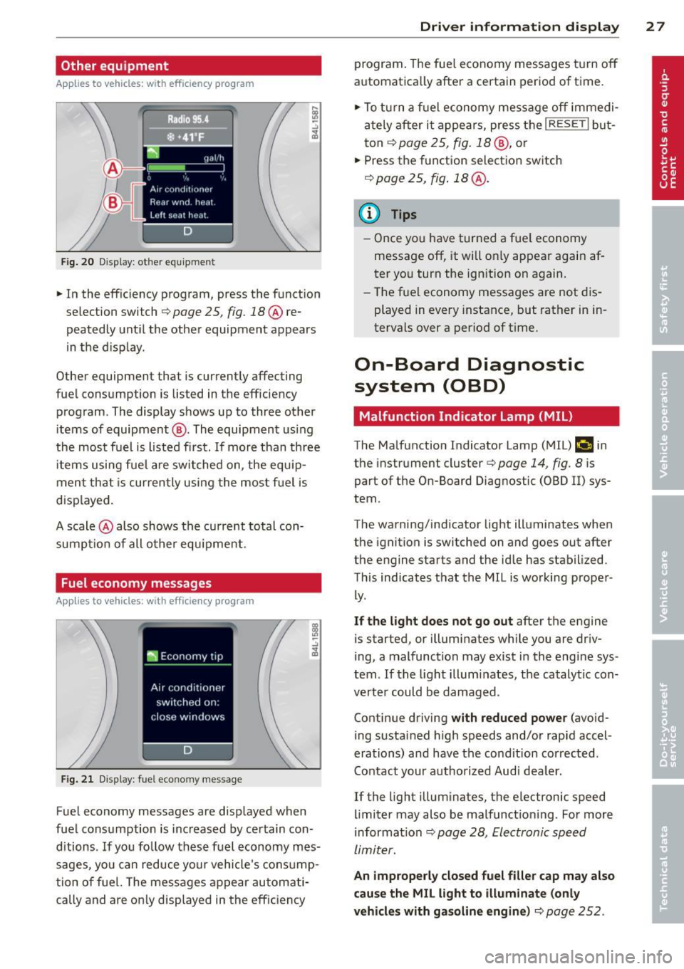
• In the efficiency program, press the function
s elec tion switch
q page 25 , fig. 18@ re
peatedly until the other equipment appears
in the d isplay .
Other equipment that i s cu rrently affecting
f uel consumption is lis ted in the eff iciency
program . The display shows up to three other
items of equipment @. The equipment using
the most fuel is l isted first. If more than three
items using fue l are switched on, the equ ip
ment that is currently using the mos t fu el is
d isp layed .
A scale @also shows the current total con
sumpt io n of all other equ ipment .
Fuel economy messages
Applies to vehicles: with efficiency program
Fig. 2 1 Dis pl ay: fuel e co n omy messa ge
-.:,
~
Fuel economy messages are displayed when
fuel consumption is inc reased by certain con
d itions . If you follow these fuel economy mes
sages, you can reduce your vehicle's consump
tion of fuel. The messages appear automati
cally and are o nly displayed in the eff ic iency
Dri ver inform ation di spl ay 2 7
program . The fue l economy messages t urn off
automatica lly after a certain period of time .
• To tu rn a f uel economy message off immedi
ately after it appears, press the
I RESE TI but
ton ¢
page 25 , fig. 18 @, or
• Press the function selection switch
r::!) page 2 5, fig . 18 @ .
{I) Tips
-Once you have turned a fuel economy
message off, it will o nly appear again af
ter yo u turn the ign ition on again.
- Th e fuel economy messages are not dis
played in
every i nstance, but rather in in
tervals
over a period of time.
On-Board Diagnostic
system (OBD)
Malfunction Indicator Lamp (MIL)
The Malfunction Indicator Lamp (M IL) ("4 in
the instrument cluster¢
page 14, fig. 8 is
part of the On-Board Diagnos tic (OBD II) sys
tem .
The warning/ind icator light ill um inates when
the ignition is switched on and goes out after
the engine star ts and the id le has stabilized.
This indicates that the M IL is working prope r
ly .
If the light does not go out after the engine
is started , or illumina tes while you are dr iv
ing, a malfunction may exist in the engine sys
tem . If the light illuminates, the catalytic con
verter could be damaged .
Con tinue driving
with reduced powe r (avoid
ing sustained high speeds and/or rapid accel
erations) and have the cond ition co rrected .
Contact your a uthorized Aud i dea ler.
If the light illum inates, the elec tronic speed
limiter may also be malfunctioning . For more
information ¢
page 28, Electronic speed
limiter.
An improperl y closed fuel filler cap ma y also
cau se the MIL light to illum inate (onl y
vehicl es with gas oline engine )¢
page 252 .
Page 30 of 340
28 Driver information d isplay
On-Board Diagnostics
Fig. 22 Locat ion of Data Link Connector (DLC)
On-Board Diagnostics monitors the compo
nents of your emission control system. Each
monitored component in your engine system
has been assigned a code . In case of a mal
function, the component will be ident ified
and the fault stored as a code in the control
module memory .
The MIL light may also illuminate if there is a
leak in the on-board fue l vapor recovery sys
tem.
If the light illuminates after a refuelling ,
stop the veh icle and make sure the fuel filler
cap is proper ly closed (on ly vehicles with gaso
line engine)
c::>page 252.
In o rder to make an accurate d iagnosis, the
stored data can only be displayed using spe
cial diagnostic equipment (generic scan tool
for OBD).
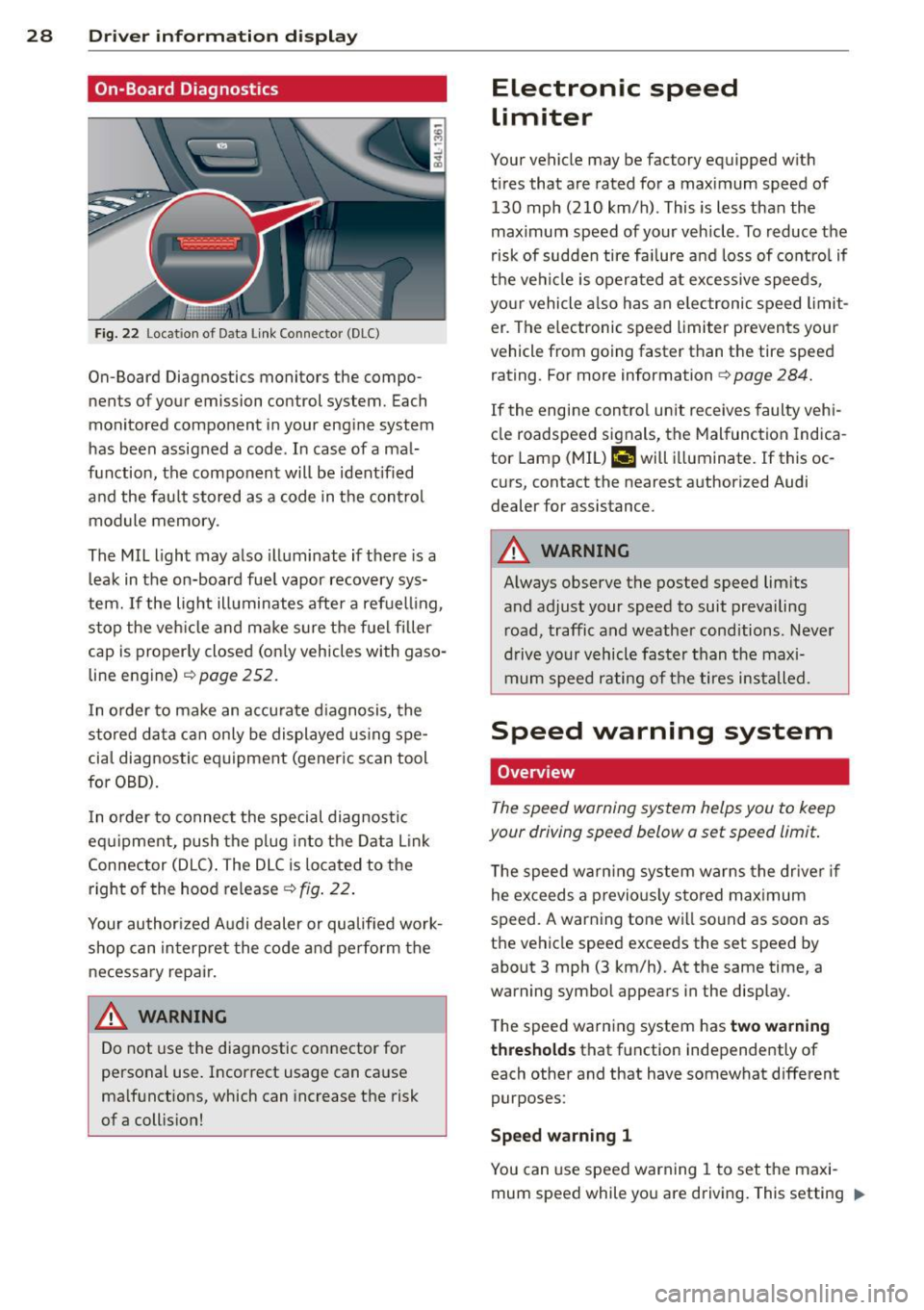
I n o rder to connect the special diagnostic
equipment, push the plug into the Data Link
Connector (DLC) . The DLC is located to the
right of the hood release
c::> fig . 22.
Your author ized Audi dealer or qualified work
shop can interpret the code and perform the
necessary repair.
A WARNING
Do not use the diagnostic connector for
personal use. Incorrect usage can cause
ma lfunctions, which can increase the risk
of a collis ion!
Electronic speed
limiter
Your vehicle may be factory equipped w ith
t ir es that are rated for a maximum speed of
130 mph (210 km/h) . This is less than the
maximum speed of your vehicle . To reduce the
risk of sudden tire fa ilure a nd loss of contro l if
the vehicle is operated at excessive speeds,
your vehicle also has an elec tronic speed limit
er . The e lectronic speed limiter prevents your
vehicle from going faster than the tire speed
rating . For more information
c::> page 284.
If the engine control unit receives faulty vehi
cle roadspeed signals, the Malfunction Indica
tor Lamp (MIL)
II will illuminate. If this oc
curs, contact the nearest authorized Audi
dealer for assistance.
A WARNING
-
Always observe the posted speed limits
and adjust your speed to suit prevailing
road, traffic and weather cond itions . Never
drive your vehicle faster than the maxi
mum speed rating of the tires installed.
-
Speed warning system
Overview
The speed warning system helps you to keep
your driving speed below a set speed limit.
T he speed warning system warns the driver if
he exceeds a previo usly stored maximum
speed . A warning tone wi ll so und as soon as
the vehicle speed exceeds the set speed by about 3 mph (3 km/h). At the same time, a
warning symbol appears in the display.
The speed warning system has
two warning
thresholds
that function independently of
each other and that have somewhat different
purposes:
Speed warning 1
You can use speed warning 1 to set the maxi
mum speed while you are driving. This setting "'