engine AUDI Q7 2014 Owner´s Manual
[x] Cancel search | Manufacturer: AUDI, Model Year: 2014, Model line: Q7, Model: AUDI Q7 2014Pages: 340, PDF Size: 85.02 MB
Page 4 of 340
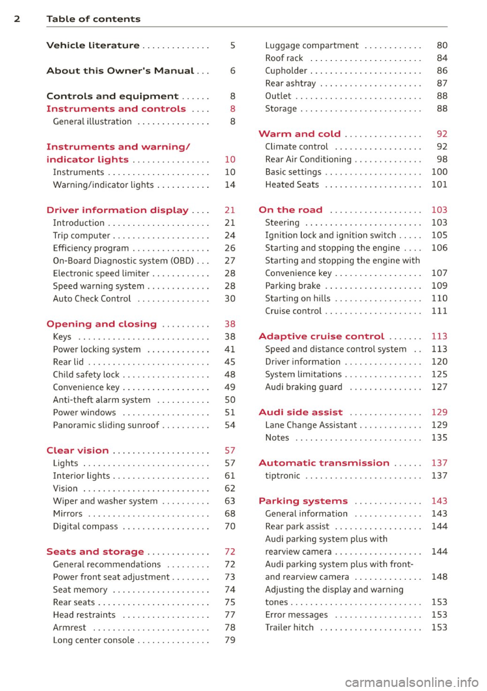
2 Table of contents Vehicle literature .. .. .. .. .. ... .
About this Owner's Manual ...
Controls and equipment .. ... .
Ins truments and controls .. . .
General illus tration .... ... .. .. ... .
Instruments and warning /
indicator lights ........ .. .. .. . .
Ins truments . .. .. ..... ... .. .. ... .
War ning/ indi cator lights ... .. ... .. .
Driver information d isplay .. . .
Introduct ion . .. .. ..... ... .. .. ... .
Trip computer .. .. ..... ... .. .. ... .
Efficiency program ........ .. .. ... .
On-Board Diagnostic system (OBD) . . .
Elect ronic speed limiter .. .. .. .. .. . .
Speed war ning system ...... ..... . .
Auto Check Control ........ ... .. . .
Opening and closing .. .. .. .. . .
Keys .. .. .. ................ ... . .
P owe r locking system . .. .. .. .. .. . .
R ear lid .. .. .. . .......... .. .. .. . .
C hild sa fety lo ck .......... .. .. .. . .
Conven ien ce key .. ..... ... .. .. ... .
Anti-theft alarm system ... .. ... .. .
Power win dows .. ..... ... .. .. ... .
Panoramic slid ing sun roof .. .. .. ... .
Clear vision .. .. ..... ... .. .. ... .
Lights . .. .. .. . .......... .. .. ... .
Inter ior lights ............. ... ... .
V 1s 1on . ...... ........... .... ... .
W iper and washer system . ... .. .. . .
M ir rors .. .. ................ ... . .
D ig ita l compass . ...... ... .. .. .. . .
Seats and storage ......... .. . .
G en eral recomme ndat ions ... .. .. . .
P owe r fron t seat adjus tment .. .. .. . .
Se at mem ory ............ .. .. ... .
Rear seats . ... . .. ..... ..... .. ... .
Head res traints .. ..... ... .. .. ... .
A rmrest .... .. .. ..... ... .. .. ... .
5
6
8
8
8
10
10
1 4
21
21
24
26
27
28
28
30
38
38
41
4 5
48
49
so
5 1
54
57
57
61
62
63
68 70
72
72 7 3
74
7 5
7 7
78
Long center conso le . . . . . . . . . . . . . . . 79
Lugga ge compartment . ..... .... . .
Roof rack ..... .. .. ... ..... ... .. .
( upholder ... .. .. .. ... .. .. .. .. .. .
Rear asht ray ..... ............. .. .
Out let .... .... .. ............. .. .
Storage ...... ... .. ............. . 80
84
86
87
88
88
Warm and cold . . . . . . . . . . . . . . . . 92
Climate control . . . . . . . . . . . . . . . . . . 92
Rea r Air Conditioning . . . . . . . . . . . . . . 98
Bas ic sett ings . . . . . . . . . . . . . . . . . . . .
100
Heated Sea ts . . . . . . . . . . . . . . . . . . . . 101
On the road . . . . . . . . . . . . . . . . . . . 103
Stee ring .. .. ... . .. ... .. ... ... .. . 103
Ig nition lo ck and ig nition sw itch . . . . . 105
St arti ng and sto pp ing t he engine . . . . 10 6
S tar ting and stopping the engine with
Co nvenience key . . . . . . . . . . . . . . . . . .
107
Pa rking bra ke . . . . . . . . . . . . . . . . . . . . 109
Starting on h ills . . . . . . . . . . . . . . . . . . 110
Cru ise contro l . . . . . . . . . . . . . . . . . . . . 111
Adaptive cruise control . . . . . . . 113
Speed and distance control system . . 113
Driver informat io n . . . . . . . . . . . . . . . . 120
System limitations . . . . . . . . . . . . . . . . 125
Audi braking gua rd . . . . . . . . . . . . . . . 127
Audi side assist . . . . . . . . . . . . . . . 129
Lane Change Assistant. . . . . . . . . . . . . 129
Not es . . . . . . . . . . . . . . . . . . . . . . . . . . 135
Automatic transmission ... .. .
tip tron ic ... ... .. .. ........ ... .. .
Parking systems
General information
Rea r park assist .. ... ... .... ... .. .
Audi par king syste m plus with
re arview c amer a .. ............... .
A udi par kin g sys tem p lus with fron t-
and rearview camera . .. ..... ... .. .
137
137
143
143
144
14 4
148
Adjusting the display and warn ing
tones..... .... .. .. ........... ...
153
Err or messages . . . . . . . . . . . . . . . . . . 153
Traile r hitc h . . . . . . . . . . . . . . . . . . . . . 153
Page 5 of 340
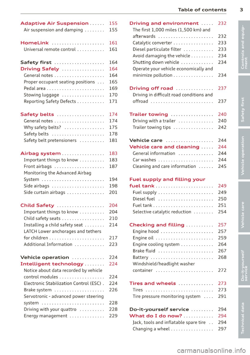
Adaptive Air Suspension .. .. . .
Air suspension and damping 155
155
Homelink . . . . . . . . . . . . . . . . . . . . . 161
Universal remote control . . . . . . . . . . . 161
Safety first . . . . . . . . . . . . . . . . . . . . 164
Driving Safely . . . . . . . . . . . . . . . . . 164
General notes ................... .
Proper occupant seating positions . . .
Pedal area .. .. ............. .. .. . .
Stowing luggage ......... .... .. . .
Reporting Safety Defects ....... ... .
Safety belts ............... .. . .
General notes ......... ...... .... .
Why safety belts? ........... .... .
Safety belts ..... .. ...... .. .. .. . .
Safety belt pretensioners .. .. .. .. . .
Airbag system .......... ... ... .
Important things to know .... .. .. . .
Front airbags ................ .. . .
Monitoring the Advanced Airbag
System .... .. .............. ... . .
Side airbags ................ ... . .
Side curtain airbags .......... ... . .
Child Safety ................. . .
Important things to know ........ . .
Child safety seats ......... .... .. . .
Installing a child safety seat .. .. .. . .
LATCH Lower anchorages and tethers
for children .... .. .. ...... .. .. .. . .
Additional Information
Vehicle operation ....... .. .. . .
Intelligent technology .. .. . .. .
164
165
169
170
171
174 174
175
178
181
183
183
187
194
198
201
204
204
210
214
217
223
224
224
Notice about data recorded by vehicle
control modules . . . . . . . . . . . . . . . . . . 224
Electronic Stabilization Control (ESC) . 224
Brake system . . . . . . . . . . . . . . . . . . . . 226
Servotronic -advanced power steering
system . . . . . . . . . . . . . . . . . . . . . . . . . 228
Driving with your quattro . . . . . . . . . . 228
Energy management . . . . . . . . . . . . . . 229
Table of contents 3
Driving and environment . . . . .
232
The first 1,000 miles (1,500 km) and
afterwards . . . . . . . . . . . . . . . . . . . . . . 232
Catalytic converter . . . . . . . . . . . . . . . . 233
Diesel particulate filter . . . . . . . . . . . . 233
Avoid damaging the vehicle . . . . . . . . . 234
Shutting down vehicle . . . . . . . . . . . . . 234
Operate your vehicle economically and
min imize pollution .. . ............ .
Driving off road .............. .
Driving in difficult road conditions and
offroad . .. .. .. .. .... ........... .
Trailer towing .... .. .. ... ..... .
Driving with a trailer ........... .. .
Trailer towing tips .. . ............ .
Vehicle care ... .. .. ........... .
Vehicle care and cleaning .... .
General information ............. .
Car washes . ....... ............. .
Cleaning and care information ..... .
Fuel supply and filling your
fuel tank ... .... .. ............. .
Fuel supply . ... .. .. ............. .
Diesel fuel .. .. ...... ........... .
Fuel tank .. .. .. .. ... ............ .
Selective catalytic reduction ....... .
Checking and filling .......... .
Engine hood ..... .... .... ... .... .
Engine oil ... .. .. .. . .. .... ...... .
Engine cooling system ............ .
Brake fluid .. .. .. ............... .
Battery ..... .. .. .. .. ........... .
Windshield/headlight washer 234
237
237
240
240
242
244
244
244
244
245
249
249
250
251
254
257
257
259
264
267
268
container . . . . . . . . . . . . . . . . . . . . . . . 272
Tires and wheels . . . . . . . . . . . . . . 273
T ires . . . . . . . . . . . . . . . . . . . . . . . . . . . 273
Tire pressure monitoring system 291
Do-it-yourself service . . . . . . . . . 294
What do I do now? . . . . . . . . . . . . 294
Jack, tools and inflatable spare tire . . 294
Changing a wheel . . . . . . . . . . . . . . . . . 297
•
•
Page 6 of 340
4 Table of contents
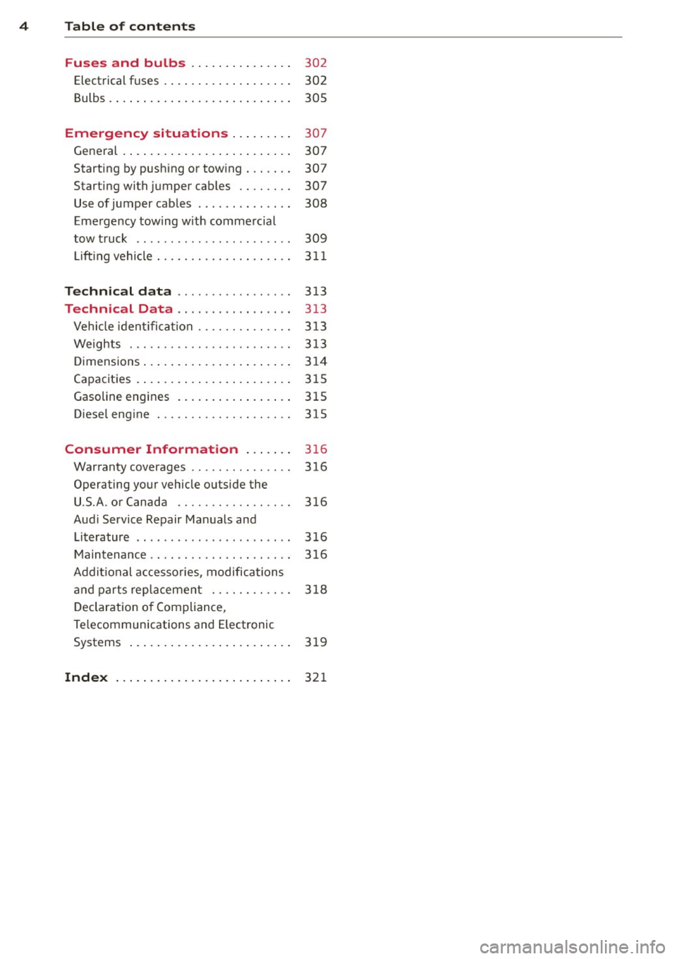
Fuses and bulbs . . . . . . . . . . . . . . .
302
Elect rical fuses . . . . . . . . . . . . . . . . . . . 302
Bulbs .. .. .. ... ... .... ... .. .. .... 305
Emergency situations . . . . . . . . . 30 7
General . . . . . . . . . . . . . . . . . . . . . . . . . 307
Starting by push ing or tow ing . . . . . . . 307
Starting with jumper cables . . . . . . . . 307
Use of jumper cab les . . . . . . . . . . . . . . 308
Eme rgency towing with commercial
tow truck . . . . . . . . . . . . . . . . . . . . . . . 309
Lift ing vehicle . . . . . . . . . . . . . . . . . . . . 3 11
Technical data . . . . . . . . . . . . . . . . . 3 13
Technical Data . . . . . . . . . . . . . . . . . 3 13
Vehicle ident ifica tion . . . . . . . . . . . . . . 3 13
Weights . . . . . . . . . . . . . . . . . . . . . . . . 3 13
D imensions .... .. ..... ... .. .. ... . 314
Capacities . . . . . . . . . . . . . . . . . . . . . . . 315
Gasoline engines . . . . . . . . . . . . . . . . . 315
Diese l eng ine . . . . . . . . . . . . . . . . . . . . 315
Consumer Information . . . . . . . 3 16
Warranty coverages . . . . . . . . . . . . . . . 316
Operating your vehicle outside the U.S.A. or Canada . . . . . . . . . . . . . . . . . 316
Audi Service Repair Manuals and Literature . . . . . . . . . . . . . . . . . . . . . . . 3 16
M aintenance.. ... .... .... .. .. .. .. 316
Addit ional accesso ries, modifications
and parts replacement . . . . . . . . . . . . 318
D eclaration o f Compliance,
Te lecommunications and E lectronic
Systems . . . . . . . . . . . . . . . . . . . . . . . . 319
Inde x . . . . . . . . . . . . . . . . . . . . . . . . . . 32 1
Page 12 of 340
10 Instruments and warning/indicator lights
Instruments and warning/indicator Lights
Instruments
Instrument cluster and controls
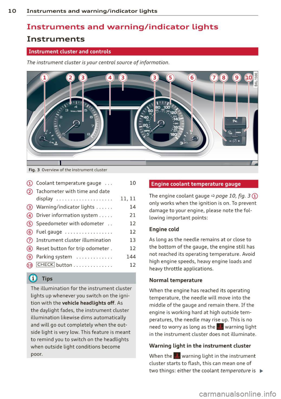
The instrument cluster is your central source of information.
Fig. 3 Ove rv iew of t he inst ru m ent cluster
CD Coolant temperature gauge . . . 10
@ Ta ch ome ter w ith time an d date
d isplay . . . . . . . . . . . . . . . . . . . . 11, 11
® Warning/indicator lights . . . . . . 14
© Driver info rmation system .. .. . 21
® Speedometer with odometer . . 12
® Fuel gauge . . . . . . . . . . . . . . . . . 12
(i) Ins trumen t clus ter ill umination 13
@ Reset button for t rip odometer . 12
® Parking system . . . . . . . . . . . . . 144
@ ICHECK I button . . . . . . . . . . . . . . 12
@ Tips
The ill umi nat ion fo r th e i nstru me nt cl uster
lights up whe never yo u switch on the i gni
tion with t he
vehicle headlights off . As
the daylight fades, the instrument cluster illumi nat ion likewise dims automatically
a n d w ill go out completely when t he out
side light is very low. This feat ure is meant
to remind you to switch on the headlights
w hen o utside lig ht con dit io ns become
poor.
Engine coolant temperature gauge
The eng ine coolant gauge q page 10, fig. 3 CD
only works when the ignition is on. To p revent
damage to you r engine, please note the fol
lowing impor tant po ints:
Engine cold
As long as the needle remains at or close to
the bottom of the gauge, the engi ne still has
not reached its operat ing temperature . Avoid
high eng ine speeds, heavy eng ine loads and
heavy th rottle a pplicat io ns.
Normal temperature
When the engine has reached its operat ing
temperature, the needle w ill move into the
midd le of the gauge and rema in the re. If th e
engine is worki ng ha rd at high outside tem
peratures, the needle may rise up. This is no
need to worry as long as the. warning light
i n the i nstr ument cluster does not ill uminate.
Warning light in the instrument cluster
When the. warn ing light in the inst rument
cluster s tarts to flash, th is can mean one of
two things : eithe r the coo lant
temperature is .,..
Page 13 of 340
Instrument s and warning /indicator lights 11
too high, or the coolant level is too low
¢ page 32.
If the needle is well in the upper area of the
ga uge , the coolant temperature is too high.
Stop the vehicle , switch the eng ine off and
allow the engine to cool.
If the warning light
comes on again after driving a short distance,
contact an authorized dealer.
A WARNING
- Always observe the warning in
¢
page 257, before opening the hood
and checking the engine coolant level.
- Never open the engine hood if you see or
hear steam, or if you see engine coolant
dr ipping from the engine compartment.
You could bu rn yourself. Let the engine
cool off first until you can no longer see
or hear steam or coolant escaping.
0 Note
- Mount ing additional lights or accessories
i n front of the a ir inlets reduces the cool
i ng effect of the radiator. At h igh outside
temperatures or high eng ine load , the
engine could overheat.
- The front spo iler has been designed to
properly distribute the cooling air when
the veh icle is moving. If the spoiler is
damaged, this cou ld reduce the cooling
effect and the engine could then over heat. Ask your authorized Audi dealer for
ass istance.
Tachometer (engine rev counter)
The tachometer indicates the engine RPM
(revolutions per minutes).
The tachometer @¢ page 10, fig. 3 is the left
of the two large clock-type displays.
The engine turns at a speed 1,000
times the
single digit in the display, e.g . if the needle is
pointing at the "2" the engine is turning at
2,000 RPM.
If engine RPM drops be low 1,500, you should
downshift to the next lower gear. The red area at
the end of the scale indicates maximum
permissible engine RPM after the break-in pe
riod. Before reaching this area , move these
lector lever to position D (Drive) or ease your
foot off the accelerator pedal.
(D Note
The tachometer needle should not move
into the red range. If it does, then only for
a very short per iod of t i me. You could
damage your engine by driving at high RPM .
@) For the sake of the environment
Upshifting early saves fuel and reduces en
gine noise .
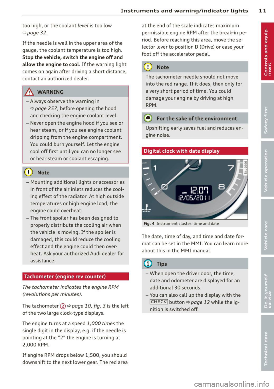
Digital clock with date display
Fig. 4 In st ru m en t cluster : time a nd da te
The date, time of day, and time and date for
mat can be set in the MMI. You can learn more
about this in the MMI manual.
(D Tips
-When open the driver door, the time,
date and odometer are disp layed for an
add itional 30 seconds.
- You can also call up the display with the
!CHECK I button q page 12 while the ig
nition is switched off.
Page 14 of 340
12 Instruments and warning/indicator lights
Speedometer with odometer
The speedometer shows you the vehicle
speed, and the odometer shows you how
many miles (kilometers) you have driven.
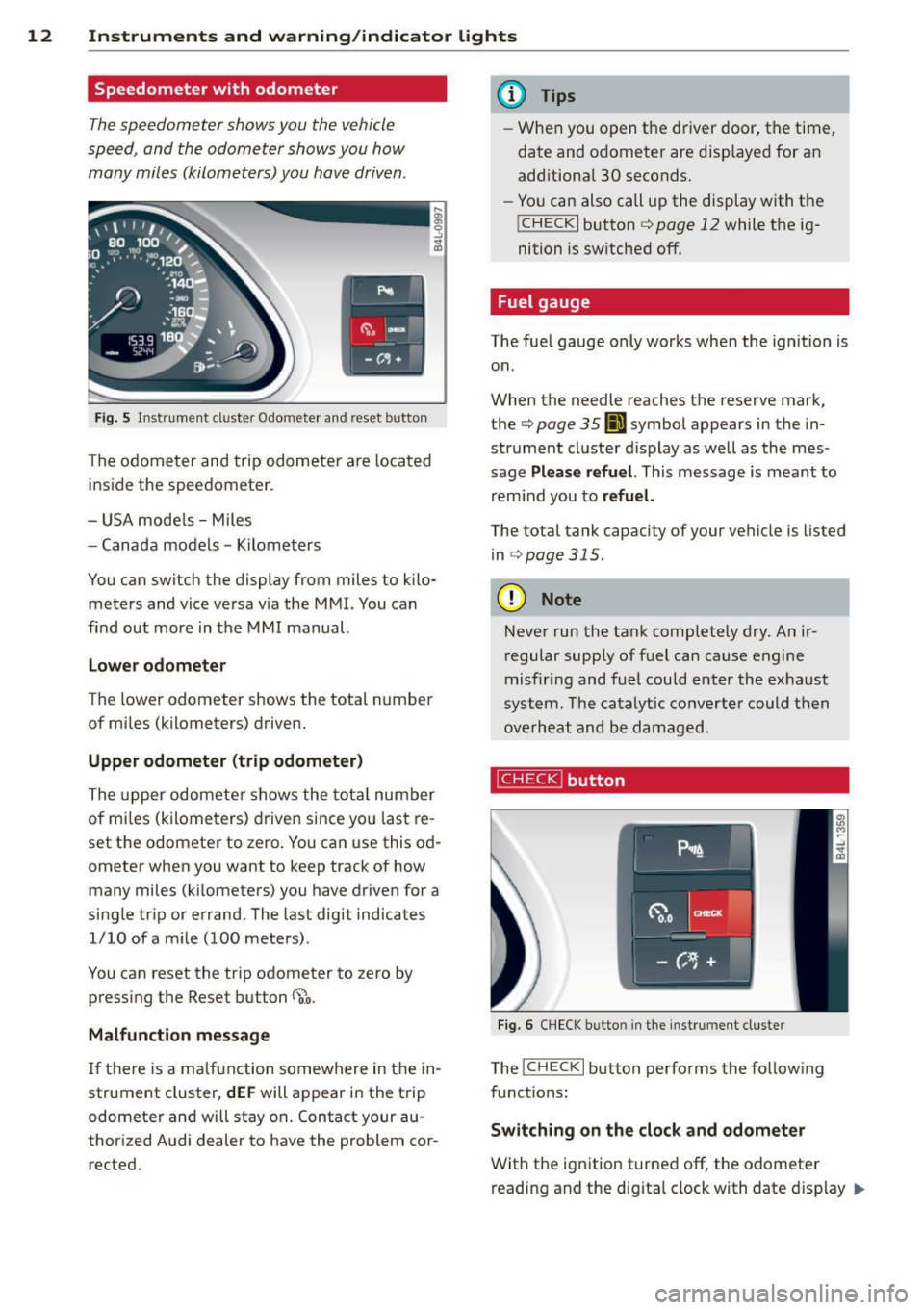
Fig. 5 Instrument cluster Odometer and reset button
The odometer and trip odometer are located
inside the speedometer.
- USA mode ls - Miles
- Canada models -Kilometers
You can switch the display from miles to kilo meters and vice versa via the MMI. You can
find out more in the MMI manual.
Lower odometer
The lower odometer shows the total number
of mi les (kilometers) driven.
Upper odometer (trip odometer)
The upper odometer shows the tota l number
of mi les (kilometers) driven since you last re
set the odometer to zero. You can use this od
ometer when you want to keep track of how many miles (k ilometers) you have driven for a
single trip or errand. The last digit indicates
1/10 of a mile (100 meters).
You can reset the trip odometer to zero by
pressing the Reset button
~o.
Malfunction message
If there is a malfunction somewhere in the in
strument cluster,
dEF will appear in the trip
odometer and will stay on. Contact your au
thorized Audi dealer to have the problem cor
rected.
(D Tips
- When you open t he driver door, the time,
date and odometer are disp layed for an
add itiona l 30 seconds.
- You can also call up the display with the
I CHECK I button c> page 12 while the ig
nition is switched off.
Fuel gauge
The fue l gauge only works when the ignition is
on .
When the needle reaches the reserve mark,
the
c> page 35 00] symbol appears in the in
strument cluster d isplay as well as the mes
sage
Please refuel. This message is meant to
remind you to
refuel.
The total tank capacity of your vehicle is listed
in .:>page 315 .
@ Note
Never run the tank completely dry. An ir
regular supply of fuel can cause engine
misfiring and fuel could enter the exhaust
system. The catalytic converter could then
overheat and be damaged.
~ button
Fig. 6 CHECK b utto n in the instrument clus ter
The !CHECK I button performs the follow ing
funct ions:
Switching on the clock and odometer
With the ignition turned off, the odometer
reading and the dig ita l clock with date display ..,_
Page 17 of 340
Instrument s and warnin g/indic ator ligh ts 15
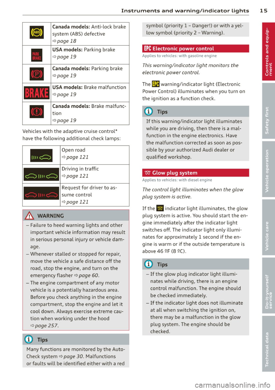
Canada m od els: Anti-lock brake
system (ABS) defective
¢ page 18
USA mode ls: Parking brake
¢page 19
Canada models : Parking brake
¢page 19
USA models: Brake malfunction
¢page 19
Canada m odels : Brake malfunc
tion
¢page 19
Vehicles w ith the adaptive cruise contro l*
have the following additiona l check lamps:
I I II c:=:)
c:=:)
I I I I c:=:)
Open road
¢ page 121
Driving in traff ic
¢ page 121
Request for driver to as
sume control
¢page 121
_& WARNING
- Failure to heed warning lights and other
important vehicle info rmation may result
in serious persona l injury or vehicle dam
age.
- Whenever sta lled or stopped for repair,
move the vehicle a safe distance off the
road, stop the engine, and turn on the
emergency flasher¢
page 60.
- The engine compartment of any motor
vehicle is a potentially hazardous area.
Before you check anything in the engine
compartment, stop the engine and let it cool down . Always exercise extreme cau
t ion when working under the hood
~ page 257.
Many functions are monitored by the Auto
Check system ¢
page 30. Malfunct ions
or faults will be identified e ither w ith a red symbol (priority 1
-Danger!) or with a ye l
l ow symbo l (priority
2 - Warning).
EPC Electronic power control
Applies to vehicles : with gasoline e ngine
This warning/indicator light monitors the
electronic power control .
The ~ warning/indicator light ( Electronic
Power Contro l) illuminates when you turn on
the ignition as a function check.
(D Tips
If this warn ing/ indica tor light illum inates
while yo u are d riving, then there is a mal
funct ion in the engine electronics. Have
the malfunct ion corrected as soon as pos
sib le by your authorized A udi dealer or
qualified workshop .
W Glow plug system
Applies to vehicles: wit h diese l eng ine
The control light illuminates when the glow
plug system is active.
If the lml indicator light illuminates, the g low
pl ug system is active . You should start the en
gine immediately after the indicator light
switches off. The indicator light only illum i
nates for approximately 1 second if the en
gine is warm or if the outs ide temperature is
above 46 QF (8 QC) .
(D Tips
-If the glow plug indicator light i llum i
nates while dr iving, there is an eng ine
cont rol malfunction . The engine should
be checked immed iate ly .
- If the ind icator light does not illuminate
at all when switch ing the ig nition on,
there may be a malfunction in the glow
plug system. The engine sho uld be
c hecked.
Page 19 of 340
Instrument s and warnin g/indic ator ligh ts 17
¢1.~ Trailer turn signal assembly
Applies to vehicles: with towing hitch
The indicator light also blinks if the turn sig
nal is operated when towing a trailer .
The indicator light. blinks when the turn
signal is used, if a trailer has been properly
connected to the vehicle .
If one of the turn signal bulbs on the trai ler is
burned out or defective, the indicator light
will not blink when you use the turn signals.
{!) Tips
For vehicles with a factory installed towing
hitch or a trailer h itch that was installed
later according to factory specifications,
the trailer tu rn signal assembly is actuat
ed.
o Malfunction Indicator Lamp (MIL)
The Malfunction Indicator Lamp (M IL) is part
of the On-Boa rd D iagnostic (OBD II) system.
The symbol
(.j ligh ts up when the ignit ion is
turned on and will turn off after the engine has started and has sett led at a constant idle
speed. This ind icates that the MIL is working
properly .
The warning light i lluminates when there is a
malfunction in the engine e lectronic system .
Contact your authorized Audi dealer and have
the malfunction corrected .
An improperly cl osed fuel fill er cap m ay al so
c au se the MIL light to illumi nate (onl y
v ehicles with ga soline eng ine)
c:> page 252.
F or more in format ion c:> page 2 7 .
Ci:> Adaptive Air Suspension
Applies to vehicles: with Adaptive Air Suspens ion
This f!I warning/indicato r light has the fo l
l owing f unctions:
- It illuminates fo r a few seconds after the ig
nition is t urned on as f unction check and
then goes out . -
If the warning/indicator light illuminates or
blinks contin uously, there is a system fault
in the Adaptive Air Suspension. A system
fau lt can result in lim ited ride comfort and
low ground clea rance . Drive safely to the
nearest authorized Audi dealer or qualified
workshop, and have the fault corrected .
- If the warning/indicator light flashes, you
should not dr ive the veh icle . The flashing
warning/indicator light points to an extreme H igh level. A very
pronounced lifting of the
veh icle (ext reme H igh leve l) can result, for
examp le, when a he avy load is removed
from the vehicle. As soon as the level has re
turned to norma l, the wa rning/indicator
light stops flashing, and you can d rive away.
- If the warning/indicator light flashes in con
junction with the
II warning/indicator
light, you should not drive off immediately
in order to prevent damage to the under
body. The two warn ing/ indicator lights
flashing together points to an extreme Low level. A ve ry
pronounced lowering of the ve
hicle (extreme Low leve l) can result, for ex
ample , from a heavy load. As soon as the
level has retu rned to normal, the warn ing/
indicator lights stop flashing, and you can
drive away.
(D Note
If the warning/ indic ator l igh t flashes in
conjunction with the
B warning/ind ica
tor light, you should not drive the vehicle
because low-lying veh icle parts can bot
tom out as yo u drive over uneven ground
and be damaged as a result.
~ Adaptive Air Suspension
App lies to vehicles: with Adaptive Air Suspension
This B warning/i ndicator light has the fo l
low ing functions:
- It illuminates for a few seconds after the ig
nition is turned on as function check and
then goes out .
- It comes on for approximately 15 seconds
as a warning of
reduced ground clearance , if .,,.
Page 21 of 340
Instruments and warning/indicator lights 19
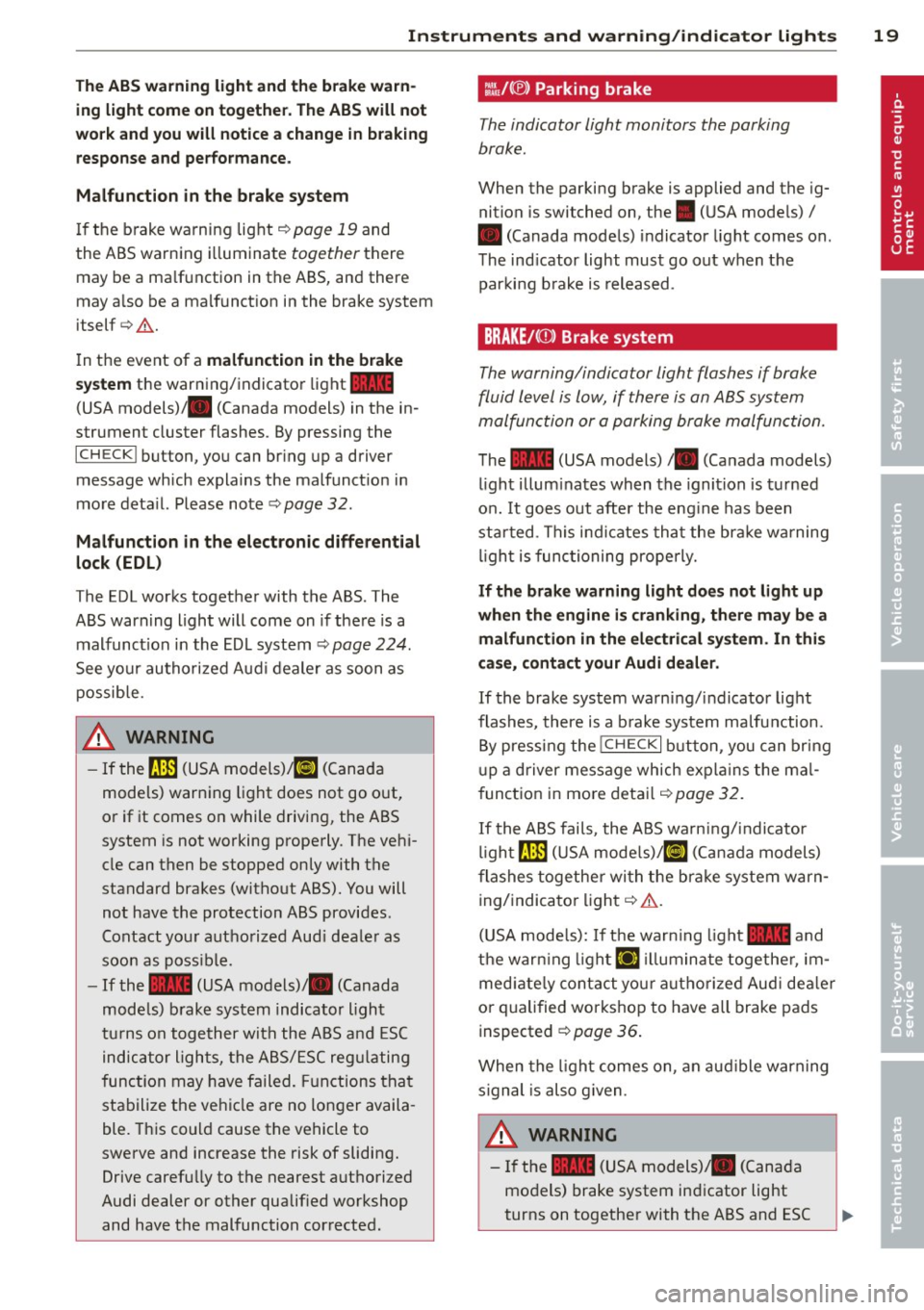
The ABS warning light and the brake warn ing light come on together. The ABS will not
work and you will notice a change in braking response and performance.
Malfunction in the brake system
If the brake warning light <=>page 19 and
the ABS warning illuminate
together there
may be a malfunction in the ABS, and there
may also be a malfunction in the brake system
itself <=>,&. .
In the event of a
malfunction in the brake
system
the warning/indicator light 1111
(USA models);III (Canada models) in the in
strument cluster flashes. By pressing the
ICHECKI button, you can bring up a driver
message which explains the malfunction in
more detail. Please note
<=>pag e 32.
Malfunction in the electronic differential
lock (EDL)
The EDL works together with the ABS. The
ABS warning light will come on if there is a
malfunction in the EDL system
<=> page 224.
See your authorized Audi dealer as soon as
possible.
.&, WARNING
-
- If the f!B (USA models);tlJ (Canada
models) warning light does not go out,
or if it comes on while driving, the ABS
system is not working properly. The vehi
cle can then be stopped only with the
standard brakes (without ABS). You will
not have the protection ABS provides.
Contact your authorized Audi dealer as
soon as possible.
- If the
1111 (USA models)/ . (Canada
models) brake system indicator light
turns on together with the ABS and ESC
indicator lights, the ABS/ESC regulating
function may have failed. Functions that
stabilize the vehicle are no longer availa
ble. This could cause the vehicle to
swerve and increase the risk of sliding.
Drive carefully to the nearest authorized
Audi dealer or other qualified workshop
and have the malfunction corrected.
:l~ /(® ) Parking brake
The indicator light monitors the parking
brake.
When the parking brake is applied and the ig
nition is switched on, the. (USA models) /
• (Canada models) indicator light comes on.
The indicator light must go out when the
parking brake is released.
BRAKE/CCDl Brake system
The warning/indicator light flashes if brake
fluid level is low, if there is an
ABS system
ma/function or a parking brake ma/function.
The 1111 (USA models)/ . (Canada models)
light illuminates when the ignition is turned
on.
It goes out after the engine has been
started . This indicates that the brake warning
light is functioning properly.
If the brake warning light does not light up
when the engine is cranking, there may be a malfunction in the electrical system. In this
case, contact your Audi dealer.
If the brake system warning/indicator light
flashes, there is a brake system malfunction .
By pressing the
I CH ECK i button , you can bring
up a driver message which explains the mal
function in more detail
<=>page 32.
If the ABS fails, the ABS warning/indicator
light~ (USA
models)/KCJ (Canada models)
flashes together with the brake system warn
ing/indicator light<=>,&. .
(USA models): If the warning light
1111 and
the warning light
El illuminate together , im
mediately contact your authorized Audi dealer
or qualified workshop to have all brake pads
inspected ¢
page 36.
When the light comes on, an audible warning
signal is also given .
.&, WARNING ~ ~
-If the 1111 (USA models) ;III (Canada
models) brake system indicator light
turns on together with the ABS and ESC
Page 24 of 340
22 Driver in formation d ispl ay
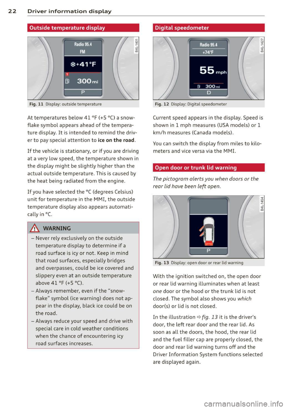
Outside temperature display
Fig. 11 Display : outside temperature
At temperatures below 41 °F (+S °C) a snow
flake symbol appears ahead of the tempera
ture display . It is intended to remind the driv
er to pay spec ial attent ion to
ic e on the roa d.
If the vehicle is stationary, or if you are driving
at a very low speed, the temperature shown in
the display might be slightly higher than the
actual outside temperature . Th is is caused by
the heat being rad iated from the engine .
If you have selected the °C (degrees Celsius)
unit for temperature in the MMI, the outside
temperature display also appears automat i
cally in
°C.
A WARNING
- Never rely excl usively on the outside
temperatu re d isplay to determine if a
road surface is icy or not . Keep in mind
that road surfaces, especially bridges
and overpasses, could be ice covered and
s li ppery even at an outs ide temperature
above 41 °F (+ S °C).
- Always remember, even if the "snow
flake" symbol (ice warn ing) does not ap
pear in the display, black ice could be on
the road.
- Always reduce your speed and dr ive with
special care in cold weather conditions
when the chance of encountering icy road s urfaces increases .
Digital speedometer
Fig. 12 Display: Digi tal speedometer
Current speed appears in the disp lay. Speed is
shown in 1 mph measures (USA models) or 1
km/h measures (Canada models) .
You can switch the disp lay from m iles to kilo
meters and vice versa via the MMI.
Open door or trunk lid warning
The pictogram alerts you when doors or the
rear lid have been left open .
Fig. 13 Display: open doo r or rea r lid wa rning
With the ign it ion sw itched on, the ope n door
or rear lid warning illuminates when at least
one door or the hood or the trunk lid is not
cl osed . The symbol a lso shows you
which
doo r(s) o r lid is not closed.
In the illustration
~ fig . 13 it is the dr iver's
doo r, the left rear door and the rear lid. As
soon as all the doors, the hood, the rear lid
and the f uel filler cap are prope rly closed, the
door and rear lid warning turns off and the
Driver Information System functions selected
are displayed again.