instrument cluster AUDI Q7 2017 Owner´s Manual
[x] Cancel search | Manufacturer: AUDI, Model Year: 2017, Model line: Q7, Model: AUDI Q7 2017Pages: 402, PDF Size: 100.39 MB
Page 4 of 402
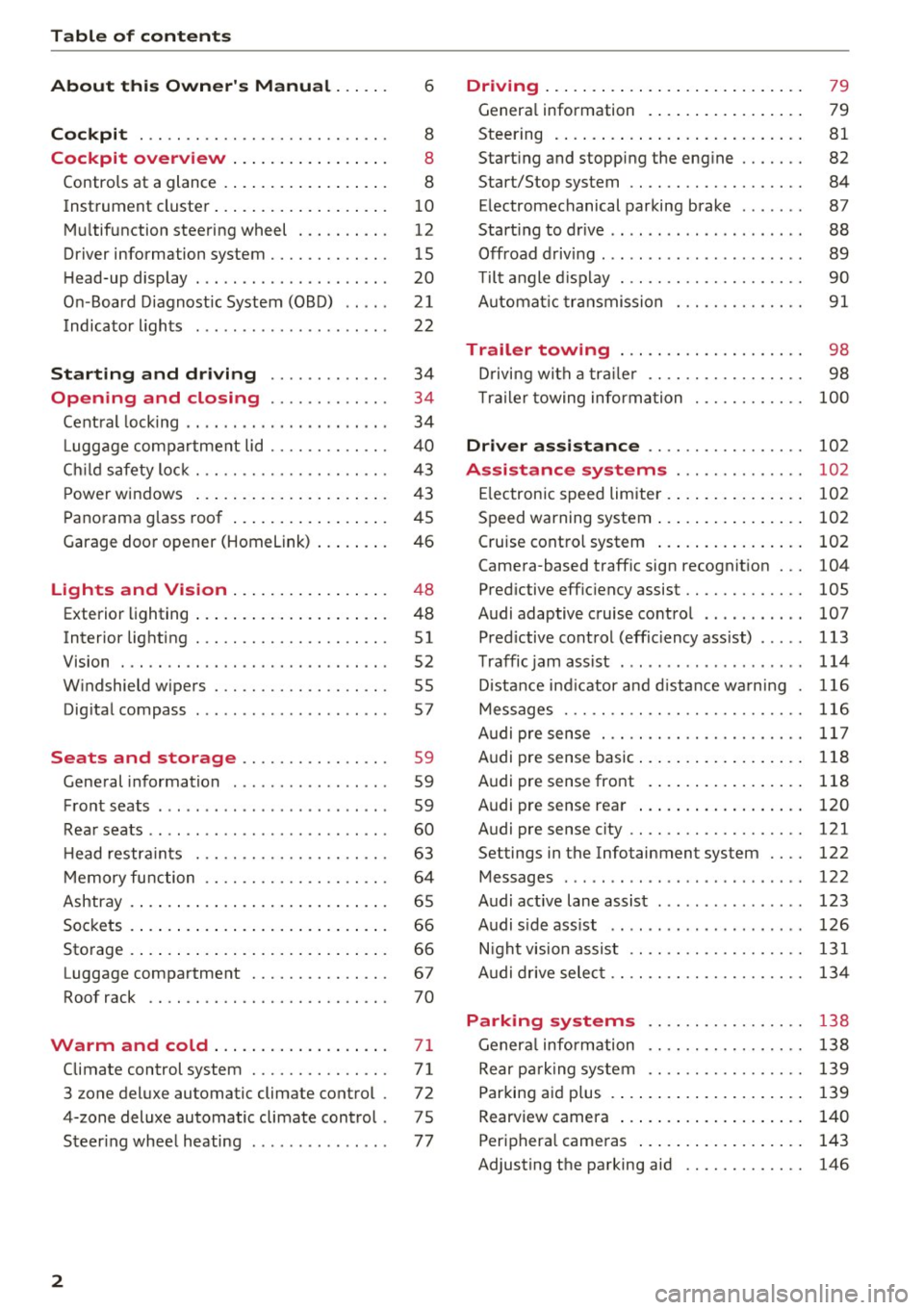
Table of contents
About this Owner's Manual ... .. .
Cockpit ... .. ............... .... .. .
Cockpit overview ................ .
Controls at a glance ... .......... .. .. .
Instrument cluster .. .......... .. .. .. .
Multifunction steering wheel ... .. .. .. .
Driver information system ............ .
H ead-up display .... .. ..... ... .. .... .
On -Board Diagnostic System (OBD) .. .. .
Indicato r lights . ................ ... .
Starting and driving ......... ... .
6
8
8
8
10
12
15
20
21
22
34
Opening and closing . . . . . . . . . . . . . 34
Central lock ing . . . . . . . . . . . . . . . . . . . . . . 34
L uggage compartment lid . . . . . . . . . . . . . 40
Ch ild safety lock . . . . . . . . . . . . . . . . . . . . . 43
Power windows . . . . . . . . . . . . . . . . . . . . . 43
Panorama glass roof . . . . . . . . . . . . . . . . . 45
Garage door opener (Homelink) . . . . . . . . 46
Lights and Vision . . . . . . . . . . . . . . . . . 48
Exterior lighting . . . . . . . . . . . . . . . . . . . . . 48
Interior lighting . . . . . . . . . . . . . . . . . . . . . 51
V1s1on . . . . . . . . . . . . . . . . . . . . . . . . . . . . . 52
Windshield wipers . . . . . . . . . . . . . . . . . . . 55
Dig ital compass . . . . . . . . . . . . . . . . . . . . . 57
Seats and storage . . . . . . . . . . . . . . . . 59
General information . . . . . . . . . . . . . . . . . 59
Front seats . . . . . . . . . . . . . . . . . . . . . . . . . 59
Rear seats . . . . . . . . . . . . . . . . . . . . . . . . . . 60
H ead restraints . . . . . . . . . . . . . . . . . . . . . 63
M emory function . . . . . . . . . . . . . . . . . . . . 64
Ashtray . . . . . . . . . . . . . . . . . . . . . . . . . . . . 65
Sockets . . . . . . . . . . . . . . . . . . . . . . . . . . . . 66
Sto rage . . . . . . . . . . . . . . . . . . . . . . . . . . . . 66
Luggage compartment . . . . . . . . . . . . . . . 67
Roof rack . . . . . . . . . . . . . . . . . . . . . . . . . . 70
Warm and cold .. .......... .. .. .. . 71
Climate control system . . . . . . . . . . . . . . . 71
3 zone deluxe automatic climate control . 72
4-zone deluxe automatic climate control . 7 5
Steer ing wheel heating . . . . . . . . . . . . . . . 77
2
Driving ..... .. .. .. .. ... .......... . .
General information . ... ........... . .
Steering .......... .. .. . .......... . .
Start ing and stopping the eng ine ..... . .
Start/Stop system .. .. ............. . .
E le ctromechanical parking brake ...... .
Start ing to drive .. .. .. ........ ..... . .
Offroad driving ... ... ...... ....... .. .
T ilt angle display . .. .. ... .......... . .
Automat ic transmission
Trailer towing ... .. ............. . .
Driving with a trail er .. .. ........... . .
T railer towing information
79
79
81
82
84
87
88
89
90
91
98
98
100
Driver assistance . . . . . . . . . . . . . . . . . 102
Assistance systems . . . . . . . . . . . . . . 102
Electronic speed limiter . . . . . . . . . . . . . . . 102
Speed warning system . . . . . . . . . . . . . . . . 102
Cruise control system . . . . . . . . . . . . . . . . 102
Camera-based traffic sign recognit ion . . . 104
Pred ictive efficiency assist. . . . . . . . . . . . . 105
Audi adaptive cruise contro l . . . . . . . . . . . 107
Pred ictive control (eff ic ie ncy assist) . . . . . 113
Traffic jam assist . . . . . . . . . . . . . . . . . . . . 114
Distance indicat or and distance warnin g 116
Messages . . . . . . . . . . . . . . . . . . . . . . . . . . 116
Audi pre sense . . . . . . . . . . . . . . . . . . . . . . 117
Audi pre sense basic . . . . . . . . . . . . . . . . . . 118
Audi pre sense front . . . . . . . . . . . . . . . . . 118
Audi pre sense rea r . . . . . . . . . . . . . . . . . . 120
Audi pre sense city . . . . . . . . . . . . . . . . . . . 121
Settings in the Infotainment system . . . . 122
Messages . . . . . . . . . . . . . . . . . . . . . . . . . . 122
Audi active lane assist . . . . . . . . . . . . . . . . 123
Audi s ide assist . . . . . . . . . . . . . . . . . . . . . 126
Night vision assist . . . . . . . . . . . . . . . . . . . 131
Audi drive select . . . . . . . . . . . . . . . . . . . . . 134
Parking systems 138
General information . . . . . . . . . . . . . . . . . 138
Rear parking system . . . . . . . . . . . . . . . . . 139
Parking aid plus . . . . . . . . . . . . . . . . . . . . . 139
Rearview camera . . . . . . . . . . . . . . . . . . . . 140
Periphera l cameras . . . . . . . . . . . . . . . . . . 143
Adjusting the parking aid . . . . . . . . . . . . . 146
Page 11 of 402
u co ...... N r-... N ...... 0
0
:E: '
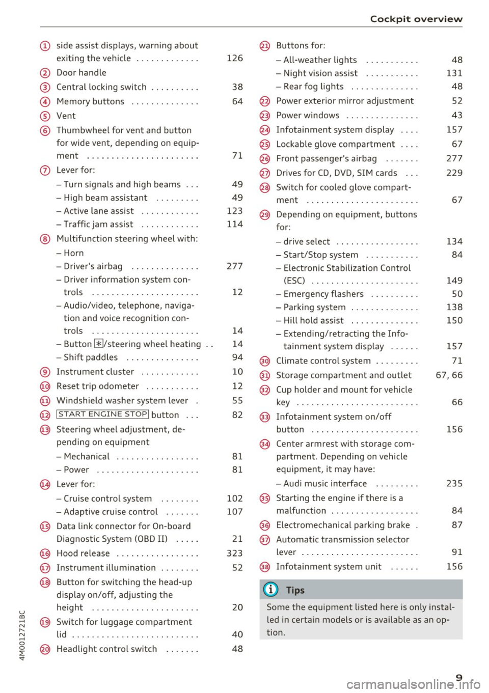
exiting the vehicle ..... ... .. .. .
@ Door handle
@ Cent ral locking switch ....... .. .
@ Memory buttons ........... .. .
® Vent
® Thumbwhee l for vent and button
for wide vent, depending on equip-
ment ... .. .... .. .... ... ... . .
0 Lever for:
- T urn s ignals and high beams . . .
- High beam assistant .... .. .. .
- Active lane assist ........... .
- T raffic jam assist ........... .
@ Mu lt if unction steer ing whee l with:
- Horn
- Drive r's airbag . ..... ... .. .. .
- Drive r informat ion system con -
trols . ... .... .. .... ... .. .. .
- Audio/v ideo, telephone, nav iga
tion and voice recognition con -
t rols .. .. ... .. ..... ... .. .. .
- Button @/steering wheel heating
- Sh if t paddles .......... .. .. .
® Instrument cluster ........... .
@ Reset t rip odometer ...... .. .. .
@ W indshield washe r system lever
@ I STAR T ENGINE ST OPI button .. .
@ Steer ing whee l adjustment, de -
pending on equipmen t
- Mechan ica l .............. .. .
- Power .... .. .. ..... ... .. .. .
@ Leverfo r:
- C ruise cont rol sys tem
- Adaptive cruise cont rol ...... .
@ Data link connector for On-board
Diagnostic System (OBD II) . ... .
@ H ood release .... . .... .... ... .
@ Ins trumen t illum ination ... .. .. .
@ Button for switch ing the head-up
d isplay on/off, adjust ing the
height .. .. ........ ..... .. .. .
@ Sw itch for lugg age compa rtment
lid . ... .. .. .. .. .. .... ... .. .. .
@ H eadlight control sw itch .... .. .
126
38
64
7 1
49
49
123
114
27 7
1 2
14
1 4
94
10
12
55
82
81
8 1
10 2
107
2 1
323
52
20
4 0
48
Coc kpit o ve rv iew
@ Buttons fo r:
- All-weather lights
- Night vision assist .......... .
- Rea r fog lights ..... . ..... .. .
@ Power exte rior m irror adjustment
@ Power windows .............. .
@ Infotainment system display
@ Lockable glove compa rtme nt
@) Front passenger 's airbag .... .. .
@ Drives for CD, DVD, SI M cards .. .
@ Swi tch for cooled glove compa rt-
me nt ...... ................ .
@ Depend ing on equ ipment, buttons
for :
- drive select ................ .
- Sta rt/Stop system ... ..... .. .
- Electronic Stabilization Control
(ESC) . .. .. .. .. ... ....... .. -
- Emergency flashers ......... .
- Parking system ............. .
- Hill hold ass ist .. .. .. ..... .. .
- Extend ing/retracting the Info-
tainment system disp lay ... .. .
@ Climate contro l system .... ... . .
@) Storage compartment and outlet
@ Cup holder and mount for vehicle
key .... .... .. .. ............ .
@ Infotai nment system on/off
button . .. .. . ............... .
@ Center armrest w ith sto rage com
partment. Depending on vehicle
equipment, it may have:
- Aud i m usic interface ........ .
@ Starting the engine if the re is a
malfunction ... .. ... .. ..... .. .
@ E lectromechanical parking brake
@ Automa tic tr ansmission se lector
lever ... .. .. .. ... .. .. ..... .. .
@ Infotainment system unit
(D Tips
48
131
48
52
43
157
67
27 7
229
6 7
134 84
149
so
138
150
1S7
71
6 7,66
66
156
2 35
84
87
91
156
Some the equipment listed here is only instal
l ed in certa in models or is available as an op
tion.
9
Page 12 of 402
Cockpit overview
Instrument cluster
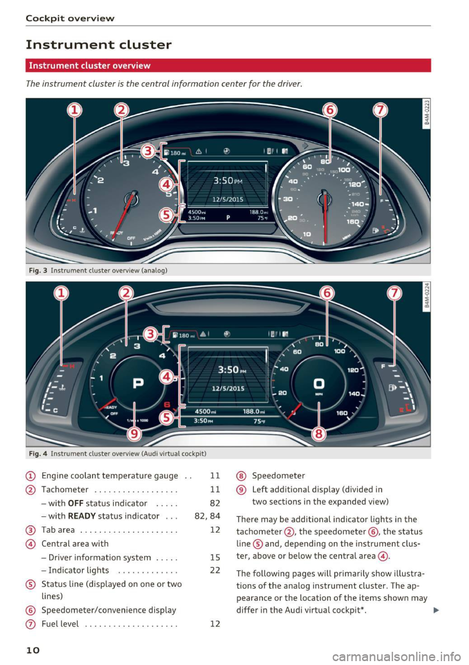
Instrument cluster overview
The instrument cluster is the central information center for the driver.
Fig. 3 Instrument cluster overv iew (analog)
F ig . 4 Instrument cluster overv iew (Audi v irtual cockpit)
(D Engine coolant temperature gauge
@ Tachometer ................. .
-with
OFF status ind icator .... .
- with
READY status indicator .. .
@ Tab area .... ... ... ....... ... .
@ Central area with
- Driver informat io n system .... .
- Indicator lights ...... ...... .
® Status line (displayed on one or two
lines)
@ Speedometer/convenience display
0 Fuel level
10
11
11
82
82,84
12
15
22
12
@ Speedometer
® Left additional display (divided in
two sections in the expanded view)
There may be additional indicator lights in the
tachometer @, the speedometer @, the status
line ® and, depending on the instrument clus
ter, above or below the central area@.
The following pages will primarily show illustra
tions of the ana log instrument cluster. The ap
pearance or the location of the items shown may
differ in the Audi virtual cockpit*. ...,
Page 16 of 402
Cockpit overview
Right control button
- Opening/closing the options menu :
press the
respective right control button on the steering
whee l~
fig. 8 . You can change any context-de
pendent functions and settings using the left
thumbwheel (for example, additional station information).
(D Tips
The availability of a se lection menu or options
menu depends on the function that is select
ed.
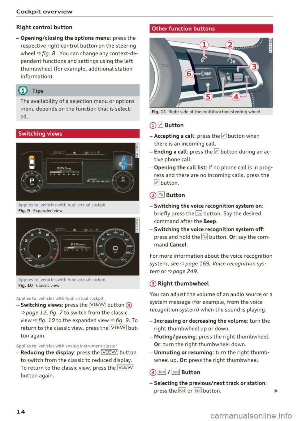
Switching views
Applies to: vehicles with Audi virtual cockpit
F ig. 9 Expanded v iew
Applies to: vehicles with Audi virtual cockpit
Fig. 10 Classic view
Applies to: vehicles with Audi virtual cockpit
- Switching views : press the IVIEW ! button @)
~ page 12, fig. 7 to sw itch from the classic
view ~
fig. 10 to the expanded view~ fig. 9. To
return to the classic view, press the IVIEW I but
ton again .
Applies to: vehicles with analog instrument cluster
-Reducing the display : press the IVIEW I button
to switch from the classic to reduced d isplay .
To return to the class ic view, press the !VIEWI
button aga in.
14
Other function buttons
Fig. 11 Right side of the multifunction steering wheel
(D 0Button
- Accepting a call:
press the 0 button when
there is an incoming call.
-Ending a call: press the 0 button during an ac
tive phone call.
- Opening the call list: if no phone call is in prog
ress and there are no incoming calls, press the
0 button.
@ ~ Button
- Switching the voice recognition system on:
briefly press the E:9 button. Say the desired
command after the
Beep.
- Switching the voice recognition system off:
press and hold the [:9 button. Or: say the com
mand
Cancel.
For more information about the voice recognition
system, see
~ page 169, Voice recognition sys
tem
or Q page 249.
@ Right thumbwheel
You can adjust the volume of an audio source or a
system message (f or example, from the voice
recognition system) when the sound is playing.
-Increasing or decreasing the volume: turn the
r ig ht thumbwheel up or down.
-Muting/pausing : press the right thumbwheel.
Or: turn the right thumbwheel down.
-Unmuting or resuming : turn the right thumb
wheel up.
Or: press the right thumbwheel.
© !1441 / l t>t>I! Button
- Selecting the previous/next track or station :
press the l1<1 <1I or lt>t> II button . .,,.
Page 17 of 402
u co ...... N r-... N ...... 0
0
:E: '
and hold the
l 1
l ocation in the fi le is reached.
®0 button I steering wheel heating ~
- Steering wheel heating (analog instrument
cluster) :
for additional information, see
¢page 77.
-Programmable steering wheel button -open
ing a function :
press them button on the mul
tifunction steering whee l.
-Programmable steering wheel button -re
questing a function :
press and hold the m but
ton .
-Programmable steering wheel button -chang·
ing a function :
press and hold the m button.
Se lect and confirm an entry.
Or
- Se lect in the Infotainment system: !MENUI but
ton >
Vehicle > left contro l button > Vehicle
settings
> Steering wheel button assignment .
® I q .. vl Button
- Repeating the last navigation prompt :
press
the
l a,w l button when route guidance is act ive .
-Changing the voice guidance volume: when
route guidance is active, tur n the right t humb
whee l upward or downward during a navigation
prompt.
Driver information
system
On-board computer
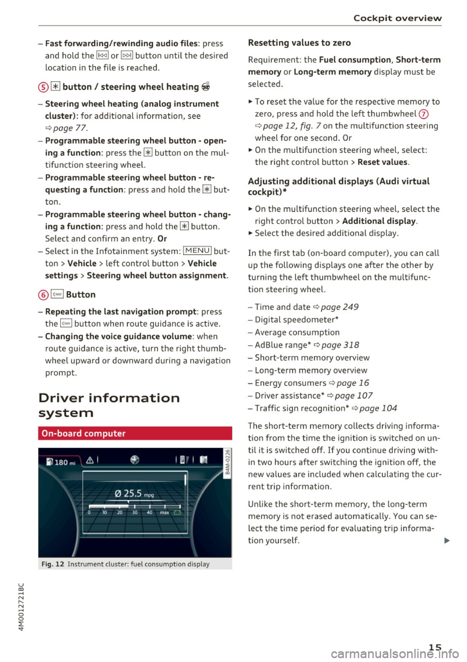
Fig. 12 Instrument cluster: fuel consumption disp lay
Cockpit overview
Resetting values to zero
Requirement: the Fuel consumption , Short-term
memory or Long-term memory
display must be
selected.
"' To reset the val ue for the respect ive memory to
zero, press and hold the left thumbwheel
0
¢ page 12, fig. 7 on the multi function steering
wheel for one second. Or
"' On the multifunction steering wheel, select:
the right control button>
Reset values .
Adjusting additional displays (Audi virtual
cockpit)*
"' On the multifunction steering wheel, select the
right control button >
Additional display .
"'Select the desired additional display.
In the first tab (on -board comp uter), you can ca ll
u p the following disp lays one after the other by
turning the left thumbwheel on the mult ifunc
tion steer ing wheel.
- Time and date¢
page 249
-Digita l speedomete r*
- Average consum ption
- AdBlue range*
¢page 318
-Short-term memory overview
- Long-term memory overview
- Energy consumers ¢
page 16
-Driver assistance * ¢page 107
-Tra ffic sign recognition* ¢page 104
The short-te rm memory collects driv ing informa
tion from the time the ignition is switched on un
til it is switched off.
If you continue driving with
in two hours after switching the ignition
off, the
new values are included when ca lculating the cur
rent trip information.
Unlike the short-term memory, the long-term
memo ry is not erased automatically. You can se
lect the time period for evaluating trip informa-
t ion yourse lf . ..,.
15
Page 20 of 402
Cockpit overv iew
@ Tips
-The telephone functions can only be con
tro lled with the multifunction steering
whee l if the telephone equipment was in
stalled
at the factory.
- The telephone functions depend on the cell
phone and whether they are supported by
your cell phone service provider or not.
- The
Call w ait ing function must be activated
i n your cell phone and in the MMI to be
alerted when there is an incoming call dur
i ng an active call. The call options depe nd
o n the cell phone and serv ice provider. You
can obtain more informat ion from yo ur cell
phone se rvice provider.
Navigation
App lies to: ve hicles w ith navigation system
Requirement: a destination must be entered
r::!> page 206, route g uidance must be started and
the navigation tab must be disp layed.
"' Press the left control button on the mult ifunc-
tion s teering wheel
r:!>page 13.
Depending on vehicle eq uipment, the following
fu nctions may be available in the d river informa
tion system .
-Di splaying nav igation dur ing acti ve route
guidance :
select and confirm Map or Str eet
view *
(analog instrument clus ter).
- Showing the map when route guidanc e is not
active :
select and co nfirm Map .
- Acce ssin g last destinations :
select and confirm
La st de stination s > the desired destination .
-Ac ce ss ing f avorite s: select and confirm Favor
it es>
the desired destination.
- Starting route guidance to the stored home
addre ss :
se lect and confi rm C ancel route guid
anc e
if necessary and then Home addre ss.
If you have not started route guidance, a com
pass (in the analog instr ument cluster) or a map
(Aud i virtua l cockp it)* will be disp layed.
- Can celing active route guidance : on the multi
funct ion steer ing wheel, select: right control
button
> Cancel route guidance .
18
Additional settings
-Select: righ t con trol b utton> desired entry.
Depend ing on the function selected, the follow
i ng addi tional settings may be possible :
- Map display
r::!> page 216
- Day/night map r::!>page 216
-Map or ientat ion r::!> page 216
-Automatic zoom r::!> page 217
Navigation view with route guidance
started
Appl ies to: vehicles with navigat ion syste m and A ud i vi rt u a l
cockp it
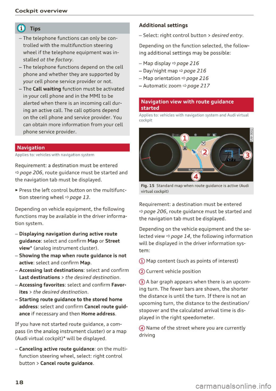
Fig . 15 Sta ndard map w hen route guidance is active (A ud i
virtual cockpit)
Requireme nt: a dest inat ion must be entered
r::!> page 206, route guidance m ust be sta rted and
t h e nav iga tion tab must be displayed.
Depend ing o n the vehicle equipment and these
l ected view
r::!> page 14, t he following informa tion
will be displayed in the d river information sys
tem :
@ A bar graph appears when there is an upcom
ing turn. The fewer bars are shown, the shorter
the d istance is unt il the turn . If there is not an
upcoming turn, the distance to the destination/
stopover and the calcu lated arriva l t ime is dis
played in the right speedometer.
@ Name of the street where you are currently
driving
Page 23 of 402
u (0 ...... N r--. N ...... 0
0
:E
-Sunglasses w ith polarization fi lters and un
favorable lighting conditions can have a negative effect on the display.
- An optimum display depends on the seat
position and the height adjustment of the
head-up display.
- A specia l windshield is needed for the head
up display function.
- For information on cleaning, see ¢
table In
terior cleaning on page
356.
On-Board Diagnostic
System (OBD)
Malfunction indicator lamp (MIL)
The malfunction indicator lamp (MIL) ¢'4 in the
instrument cluster is part of the On-Board Diag
nostic System (OBD II).
The indicator light turns on when the ignition is
switched on and turns off once the engine is
started and is running in idle at a stable speed.
This indicates that the MIL is functioning correct
ly .
If the light does not turn off after starting the
engine
or turns on while driving, this may indi
cate there is a malfunction in the engine. If the indicator turns on, the catalytic converter may be
damaged .
Drive
with reduced engine performance (avoid
high speeds for extended periods of time and/or
fast acceleration) and have the malfunction cor
rected. See an authorized Audi dealer or author
ized Audi Service Fac ility .
The electronic speed limiter may be faulty if the
indicator light turns on . For additional informa
tion, see¢
page 102, Electronic speed limiter .
The MIL indicator light may also turn on if the
fuel filler cap is not closed correctly
c> page 316.
Cockpit overview
On-Board Diagnostics
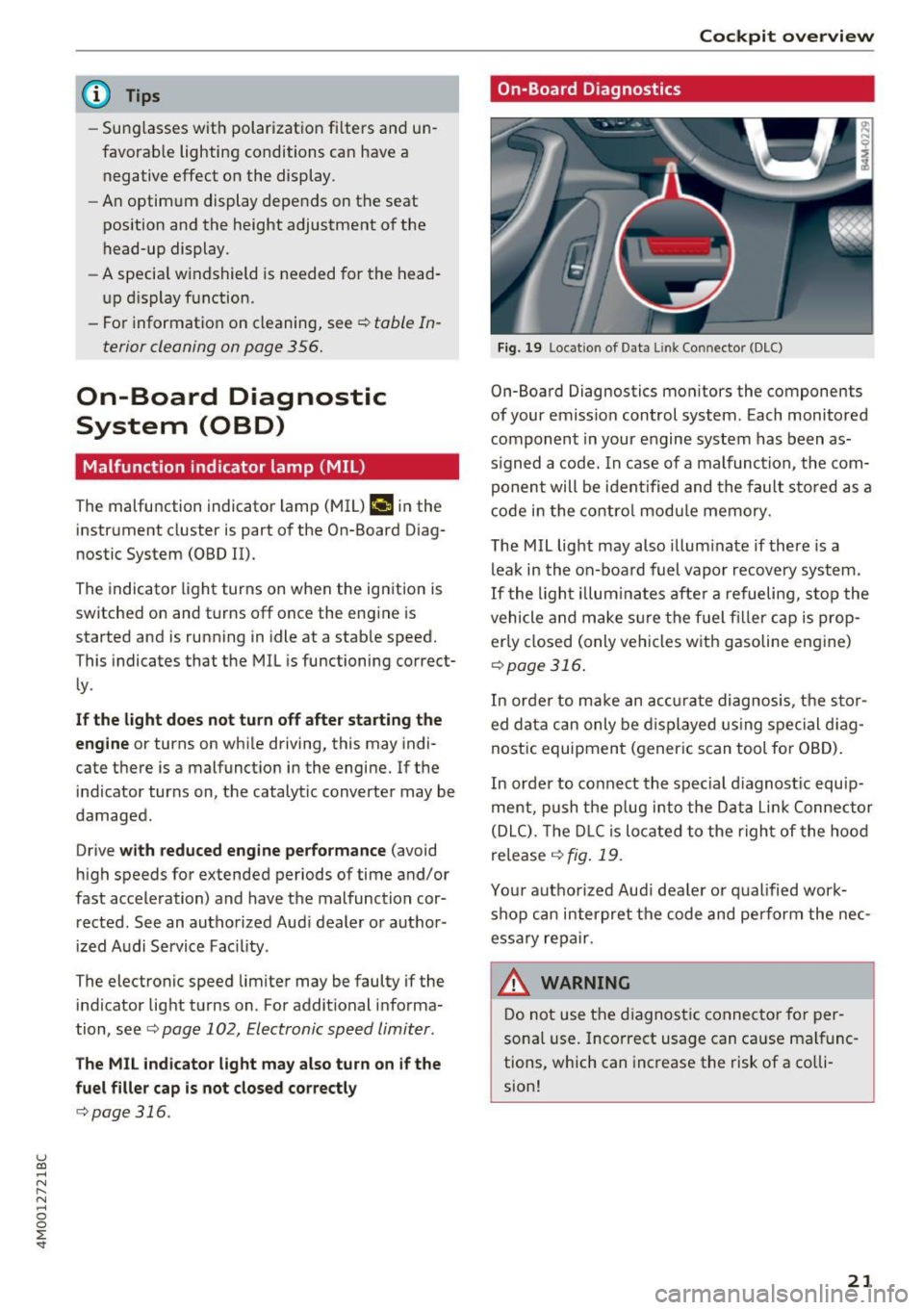
Fig. 19 Locatio n of Data Li nk Connector (DLC)
On-Board Diagnostics monitors the components
of your emission control system. Each monitored
component in your engine system has been as
s igned a code. In case of a malfunction , the com
ponent will be identified and the fault stored as a
code in the control module memory.
The MIL light may also illuminate if there is a
leak in the on-board fuel vapor recovery system.
If the light illuminates after a refueling, stop the
vehicle and make sure the fuel filler cap is prop
erly closed (only vehicles with gasoline engine)
<=>page 316 .
In order to make an accurate diagnosis, the stor
ed data can only be displayed using special diag
nostic equipment (generic scan tool for OBD).
In order to connect the special diagnostic equip
ment, push the plug into the Data Lin k Connector
(DLC). The DLC is located to the right of the hood
release
¢ fig . 19 .
Your authorized Aud i dealer or qualified work
shop can interpret the code and perform the nec
essary repair.
_& WARNING ~ ~ ·
Do not use the diagnostic connector for per-
sonal use. Incorrect usage can cause malfunc
tions, which can increase the risk of a colli
sion!
21
Page 24 of 402
Cockpit over view
Indicator lights
Description
The indicato r lights in the inst rument cluste r
b link or t urn on. They indicate funct ions or ma l
functions .
Messages may appear with some indicator lights .
A wa rni ng signal w ill sound at the same time.
The indica to r lights and messages in the instru
ment cluster display can be covered by other d is
p lays. To show them again, select the second tab
with the mu ltifunction steering wheel
¢ page 12 .
If there are several malfunctions, you can display
them one at a time using the thumbwheel.
Some ind icator lights in the disp lay can display in
several colors .
& Central indicator light
If the . or Q indicator light turns on, check
the message in the instrument cluster .
Overview
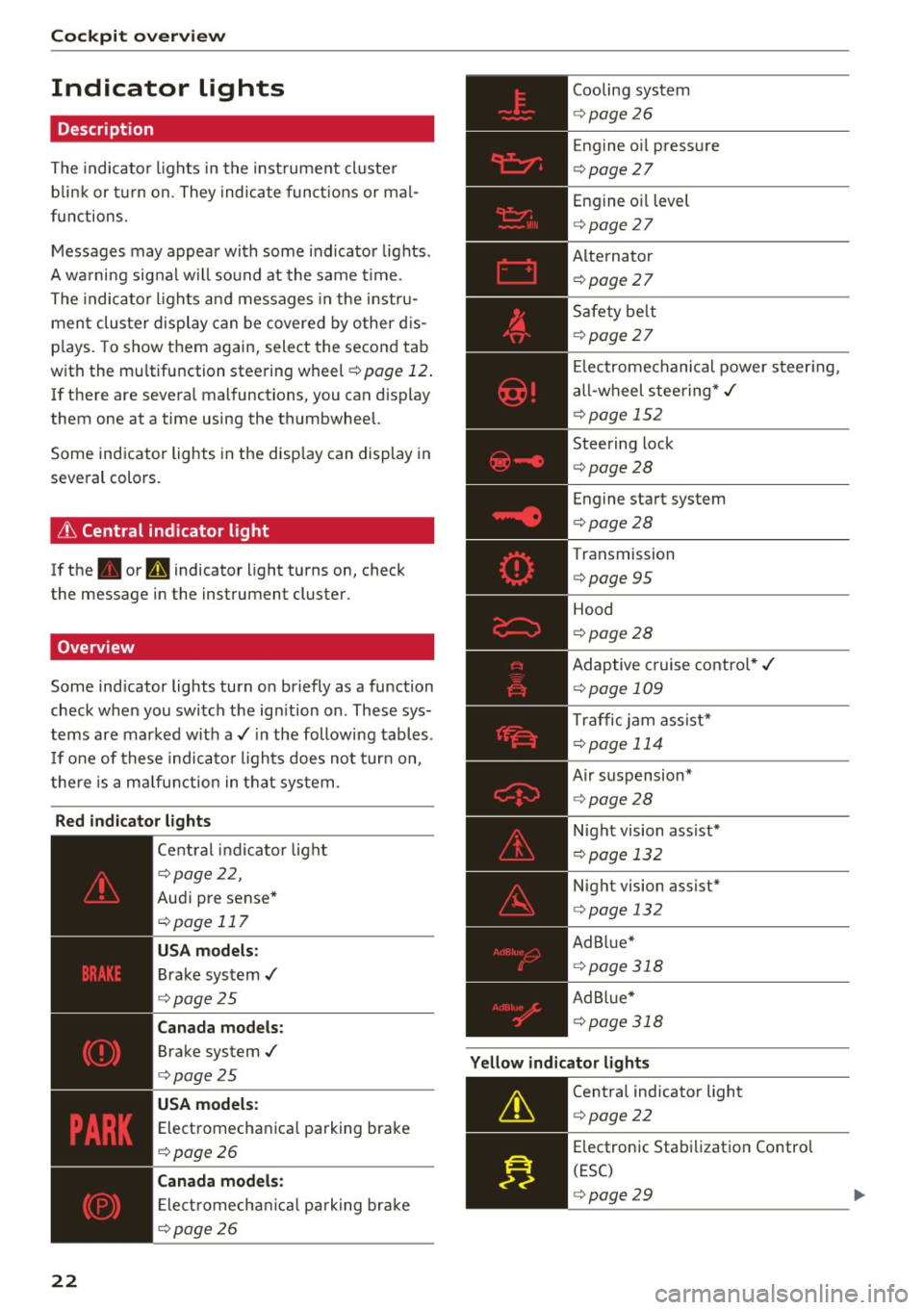
Some indicator lights turn on briefly as a function
check when you switch the ign ition on . These sys
tems are marked with a./ in the following tables .
I f one of these indicato r lights does not turn on,
there is a malfunction in that system .
Red indicator lights
22
--------------
Central indicator light
r=;, page 2 2,
Aud i pre sense*
r=;, page 117
USA models :
Brake system ,/
r=;, page 25
Canada models:
Brake system .I
r=;, page 25
USA models :
Electromechanica l parking brake
r=;, page 26
C anada models:
Ele ct romecha nical park ing brake
r=;, page 26
Cooling system
r=;, page 26
Engine o il pressure
r=;, page 27
Engine oil level
¢ page 27
Alterna tor
¢ page 27
Safety be lt
¢ page 27
El ectromechanical power steer ing,
a ll-wheel steering* ,/
¢page 152
Steering lock
¢page 28
Engine start system
r=;, page 28
Transmission
¢ page 95
Hood
¢page 28
Adaptive cruise contro l* ,/
r=;, page 109
Traffic jam ass ist*
¢ page 114
Air suspension*
r=;, page 28
Night vision assist*
r=;, page 132
Night vision assist*
r=;, page 132
Ad B lue*
r=;, page 318
Ad Bl ue*
¢ page 318
Yellow indicator lights
--------------
Centra l indicator light
r=;, page 22
Electronic Stabilization Contro l
(ESC)
¢ page 29
Page 45 of 402
u (0 ...... N r--. N ...... 0
0
:E
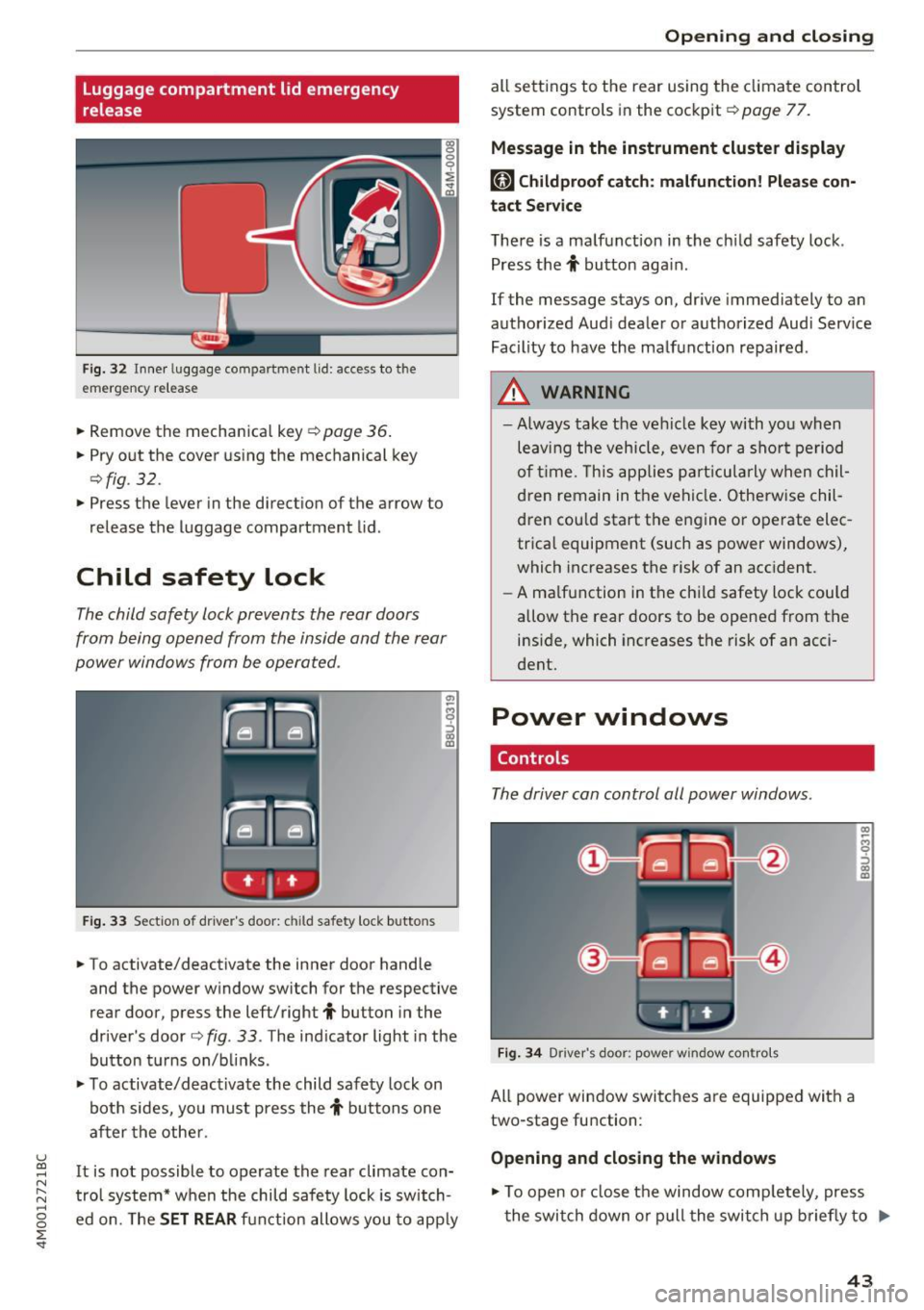
release
Fig . 32 Inner luggage co mpartme nt lid : access to the
emerge ncy re le ase
• Remove the mechanica l key ~ page 36 .
• Pry o ut the cover us ing the mechanical key
¢ fig . 32 .
• Press the lever in the direct io n of the arrow to
release the luggage compartment lid .
Child safety lock
The child safety lock prevents the rear doors
from being opened from the inside and the rear
power windows from be operated .
Fig. 33 Sect io n of dr ive r's door : chil d sa fety lock b utto ns
• To activate/deactivate the inner door handle
and the power w indow switch for the respective
rear door , press the left/right
t button in the
driver 's door ¢
fig. 33 . The ind icator light in the
bu tton turns on/b links .
• To activate/d eact ivate the child safety lock on
bot h sides, yo u must press the
t buttons one
a fter the othe r.
It is not possible to operate the rear climate con
tro l system* w hen the child safe ty lock is switch
e d on. The
SET REAR fu nction allows y ou to app ly
Open ing and closing
all sett ing s to the rear using the cl imate control
system controls in the cockpit ¢
page 77.
Message in the instrument cluster display
[81 Childproof catch : malfun ction! Please con·
tact Service
The re is a ma lfunction in the ch ild safety lock .
Press the
t button aga in .
If the message stays on, dr ive immediately to an
authorized Aud i dealer o r a uthorized Aud i Serv ice
Facility to have the ma lf u nction repaired .
A WARNING
=
-Always take the ve hicl e key with yo u when
leav ing the vehicle, even for a s hort pe riod
o f ti me. This applie s pa rtic ula rly w hen chil
dren remain in t he vehi cle. O therwise chil
d ren cou ld sta rt the en gine or operate elec
trica l equipment (such as power windows),
which increases the risk of an acc ident.
- A ma lf u nction in the ch ild safety loc k could
allow the rear doors to be opened from t he
inside, which increases the risk of an acci
dent.
Power windows
Controls
The driver can control all power windows.
F ig . 34 Dr iver 's doo r: pow er w indow co ntro ls
All power win dow switc hes are equipped wit h a
two-stage fu nction :
Opening and closing the windows
-
CX) ~ M 0
::'> CX) (D
• To open o r close the window comp letely, press
t he swi tch down or pull the swi tch up briefly to
IJi,,-
43
Page 51 of 402
u (0 ...... N r--. N ...... 0
0
:E
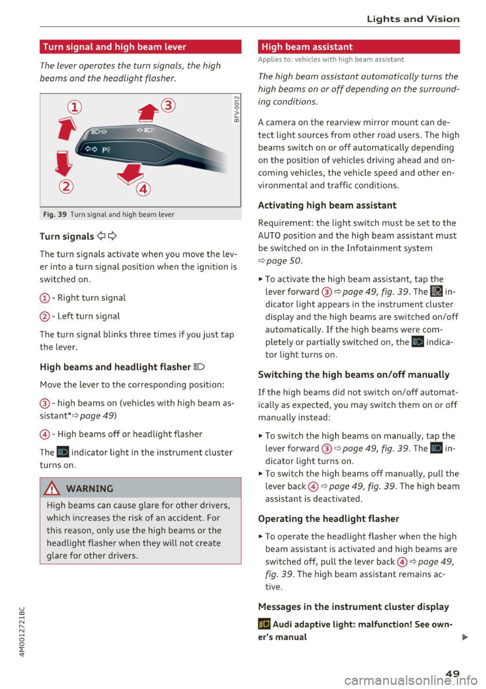
The lever operates the turn signals, the high
beams and the headlight flasher .
Fig. 39 Turn signal and high beam lever
Turn signals ¢¢
N
0 0
> u. C0
The turn signals activate when you move the lev
e r i nto a turn s ignal position when the ign ition is
switched on.
(D -Right turn signa l
@-Left turn signal
The turn s ignal blinks three times if you just tap
the lever.
High beams and headlight flasher ~D
Move the lever to the corresponding position:
@ -high beams on (vehicles w ith high beam as
sistant* ¢
page 49)
© -High beams off or headlight flasher
The
II ind icator light in the instrument cluster
turns on.
A WARNING
H igh beams can cause glare for other drivers,
which increases the risk of an acc ident. For
this reason, only use the h igh beams or the
head light flasher when they w ill not create
glare for other drivers.
Lights and V ision
High beam assistant
App lies to : vehicles wi th high beam assistant
The high beam assistant automatically turns the
high beams on or off depending on the surround
ing conditions .
A camera on the rearview mirror mount can de
tect light sources from other road users . The high
beams sw itch on or off automatically depending
on the posit io n of vehicles driving ahead and on
coming vehicles, the vehicle speed and other en
vironmental and traffic conditions.
Activating high beam assistant
Requirement: the light sw itch must be set to the
AUTO posit ion and the high beam ass istant must
be switched on in the Infota inment system
¢p age 50.
.,. To act ivate the high beam ass istant, tap the
lever forward @¢
page 49, fig . 39 . The lj!a in
d icator light appears in the instrument cluster
disp lay and the high beams a re switched on/off
automatically. If the high beams were com
p letely or partially switched on, the
II indica
to r light turns on.
Switching the high beams on/off manually
If the high beams did not switch on/off automat
ically as expected, yo u may swi tch them on or off
man ua lly ins tead:
.,. To switch the h igh beams on manua lly, tap the
lever forwa rd @ ¢
page 49, fig. 39. The II in
dicator light turns on.
.,. To switch the high beams off manually, pull the
lever back@¢
page 49, fig. 39. The high beam
assistant is deactivated .
Operating the headlight flasher
.,. To operate the headlight flasher when the high
beam ass istant is activated and high beams are
sw itched off, pull the lever back©¢
page 49,
fig. 39.
The high beam assistant remains ac
tive .
Messages in the instrument cluster display
ml Audi adaptive light: malfun ction! See own-
er's manual ..,.
49