width AUDI Q7 2020 Owner´s Manual
[x] Cancel search | Manufacturer: AUDI, Model Year: 2020, Model line: Q7, Model: AUDI Q7 2020Pages: 316, PDF Size: 113.87 MB
Page 90 of 316

Stowing and using
attachments from the Audi Genuine Accesso-
ries program are recommended.
— Make sure the roof rack is mounted on the vehi-
cle only at the specified locations > fig. 90.
— Note the permitted axle load, permitted total
weight, and permitted roof load of your vehicle
=> page 298. The roof load is the total of the
weight of the roof rack, the attachments and
the cargo you are carrying. However, you must
also note the permitted load of the carrier sys-
tem being used.
ZA\ WARNING
— Follow the installation instructions provided
with the roof rack system. If you do not se-
cure the roof rack system and objects on the
roof correctly, they could come loose from
the vehicle and cause an accident.
— The risk of an accident increases when using
a roof rack system, because it changes the
driving characteristics by shifting the center
of gravity and/or the increasing the surface
area exposed to wind. You may need to
adapt your driving style and speed to the
current conditions. We recommend that you
do not drive faster than 80 mph (130
km/h).
— Distribute the cargo evenly on the roof rack
and do not exceed the maximum width or
the maximum total roof load weight.
— Before every trip, all bolts and connections
on the roof rack must be checked. Tighten
them if necessary and recheck them regular-
ly. If you do not do this, there is a higher risk
of
the roof rack or the attachments loosen-
ing or falling off.
@) Note
— If you use other roof luggage rack systems
or do not install the roof racks as specified,
then any damage to the vehicle is not cov-
ered by the warranty. Carefully follow the
assembly and installation instructions in-
cluded with the roof rack carrier system.
—To reduce the risk of damage, you must re-
move the roof rack and attachment before
taking your vehicle through an automatic
car wash.
838
— Make sure that the luggage compartment
lid and the panoramic glass roof* do not
come into contact with objects on the roof
when they are open.
@) For the sake of the environment
Energy usage will increase because of the in-
creased wind resistance. Remove the roof rack
when you are no Longer using it.
Page 121 of 316

4M1012721BA
Assist systems
Surrounding area Radar sensors
detection Depending on the vehicle equipment, the area
surrounding the entire vehicle may be detected
> fig. 98.
The wheel sensors on the rear corners of the vehi-
cle are positioned so that the adjacent lanes to
the left and right are detected on roads with a
normal lane width.
RAZ-0612
Ultrasonic sensors
Depending on vehicle equipment, various areas
may be displayed in the MMI using the ultrasonic
(1) sensors > fig. 98.
The range of the displays depends on the location
of the ultrasonic sensors:
@ Approximately 4 ft (1.20 m)
@® Approximately 3 ft (0.90 m)
@® Approximately 5.2 ft (1.60 m)
© Approximately 3 ft (0.90 m)
Cameras
Use the camera image on the display to assist you
only if it shows a good, clear picture. Keep in
mind that the image in the display is enlarged
and distorted. Under certain circumstances, ob-
jects may appear different and unclear on the dis-
play.
[RAZ-0212|
The rearview camera can only detect the area
marked in red > fig. 99. Only this area is dis-
played on the upper display > A\.
| A WARNING
Fig. 99 Diagram: coverage area of the rearview camera Sensors and cameras have spots in which the
surrounding area cannot be detected. Objects,
animals, and people may only be detected
with limitations may not be detected at all.
Always monitor the traffic and the vehicle's
surroundings directly and do not become dis-
tracted.
The assist systems analyze the data from various
sensors and cameras installed in the vehicle. Do
not use any assist systems if there is damage to
the vehicle in an area where sensors and cameras
are located or on the vehicle underbody, or if the
vehicle was involved in a collision. The functional-
ity of the sensors and cameras could be impaired, @) Note
or they could malfunction. Have an authorized :
Audi dealer or authorized Audi Service Facility ~ Obstacles may disappear from the measure-
check their function. ment range when approaching them, even if
they were already detected. >
119
Page 152 of 316

Driver assistance
Facility immediately to have the malfunction cor-
rected.
Side assist
Descript
Applies to: vehicles with side assist
2
|
g ie
Fig. 123 Diagram: driving situations and displays in the ex-
terior mirror (example)
General information
Side assist monitors the blind spot and traffic in
the adjacent lanes behind the vehicle. Within sys-
tem limits, side assist can detect traffic that is
approaching from behind and provide a warning
when you are changing lanes and turning. The
system uses the data from the radar sensors at
the rear corners of the vehicle.
The side assist is active at walking speeds and
higher. If an object that is classified as critical is
approaching, the display in the exterior mirror @)
on the corresponding side of the vehicle will light
up.
Driving situations
The system can provide warnings about the fol-
lowing risks:
@ Approaching vehicles: a vehicle may be clas-
sified as critical in some cases, even if it is
150
farther away. The faster a vehicle ap-
proaches, the sooner the display will turn on.
Vehicles traveling in the same direction: the
display will turn on if vehicles traveling in the
same direction as your vehicle are classified
as critical. The side assist warns you of all de-
tected vehicles when they are in the “blind
spot” or before they reach that point.
@® Vehicles you are passing: the display only
turns on if you slowly pass a detected vehicle
(difference in speed between the two vehicles
is less than 9 mph (15 km/h)). There is no
display if you pass a vehicle more quickly.
Information stage
At the information level, the side assist informs
you of detected objects that are classified as criti-
cal. This is even possible when your vehicle is sta-
tionary and the turn signal is turned on, so that
the system can also assist you when turning.
From speeds of approximately 6 mph (10 km/h)
and higher, the system will warn you of detected
objects that are classified as critical, even if the
turn signal is not turned on.
The display remains dim in the information stage
so that you are not distracted while looking for-
ward.
Warning stage
If you activate a turn signal and the display flash-
es brightly, side assist is warning about objects
that have been classified as critical.
Depending on the vehicle equipment and other
driver assistance systems, the display may also
flash if you have not activated a turn signal. If
you are approaching a detected lane marker line
and it appears you will be leaving the lane, the
display will warn you about detected vehicles
that are classified as critical. You can also be
warned with corrective steering > page 144,
Lane departure warning.
Detection range
The radar sensors are designed to detect the left
and right adjacent lanes when the road lanes are
the normal width. In some situations, the display
may turn on even though there is no vehicle >
Page 162 of 316
Parking and maneuvering
@ You should stop driving in reverse when the
red orientation line touches the edge of an
object, at the latest.
Trailer view
Applies to: vehicles with trailer view
The trailer view > fig. 133 assists you in position-
ing the vehicle in front of a trailer.
— Applies to: vehicles with peripheral cameras:
Switch to the Rear view G) > page 161,
fig. 134.
— Select Trailer view in the upper display when
the parking aid is active |].
Now you can position your vehicle in front of the
trailer. The orange orientation line ©) ° fig. 133
indicates the expected path toward the trailer
hitch. Use the blue markings © to help you esti-
mate the distance to the trailer hitch. Each mark-
ing represents approximately 1 foot (0.30 me-
ters). The width of the blue surface represents
the maximum steering wheel angle.
Symbols
If $2/€9/< is displayed and the display area
represented by that symbol is not available, then
the camera on the that side is not available. The
power exterior mirrors may have been folded in
or a door or the luggage compartment lid may
have been opened.
If # is displayed, there is a system malfunction
and the display area represented by that symbol
is not available. The camera is not working in this
area.
If Nvis displayed, the respective ultrasonic sensor
is icy or dirty. Clean the area in front of the sen-
sors > page 120.
If one of the symbols continues to be displayed,
drive immediately to an authorized Audi dealer or
authorized Audi Service Facility to have the mal-
function repaired.
160
Z\ WARNING
— Follow the safety precautions and note the
limits of the assist systems, sensors, and
cameras > page 118.
— Sensors and cameras have spots in which
the surrounding area cannot be detected.
Objects, animals, and people may only be
detected with limitations may not be detect-
ed at all. Always monitor the traffic and the
vehicle's surroundings directly and do not
become distracted.
@) Note
— The orange orientation lines @) show the di-
rection the rear of the vehicle will be travel-
ing, based on the steering wheel angle. The
front of the vehicle swings out more than
the rear of the vehicle. Maintain plenty of
distance so that an exterior mirror or a cor-
ner of the vehicle does not collide with any
obstacles.
— Keep enough distance from the curb to
avoid damage to the rims.
— Only use the images provided by the camera
on the rear of the vehicle when the luggage
compartment lid is completely closed. Make
sure any objects you may have mounted on
the luggage compartment lid do not block
the rearview camera.
@ Tips
— Applies to vehicles with air suspension: The
accuracy of the orientation lines and blue
surfaces on the camera display decreases
when the vehicle is raised or lowered with
the air suspension.
— There is no rear distance warning when trail-
er mode is detected. The front sensors re-
main activated. The visual display switches
to trailer mode. The rearview camera image
will not show the orientation lines and the
blue surfaces. There is no guarantee the
functions will be deactivated when using a
retrofitted trailer hitch.
Page 249 of 316
4M1012721BA
Wheels
Tire designations
B8K-2316
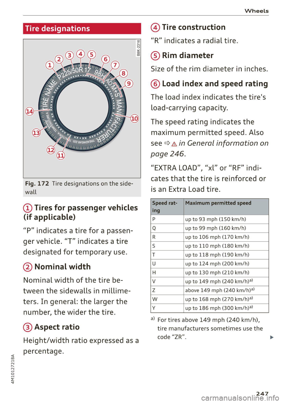
Fig. 172 Tire designations on the side-
wall
@ Tires for passenger vehicles
(if applicable)
“P” indicates a tire for a passen-
ger vehicle. “T” indicates a tire
designated for temporary use.
@ Nominal width
Nominal width of the tire be-
tween the sidewalls in millime-
ters. In general: the larger the
number, the wider the tire.
@) Aspect ratio
Height/width ratio expressed as a
percentage.
@ Tire construction
“R” indicates a radial tire.
©) Rim diameter
Size of the rim diameter in inches.
© Load index and speed rating
The load index indicates the tire's
load-carrying capacity.
The speed rating indicates the
maximum permitted speed. Also
see > A in General information on
page 246.
“EXTRA LOAD”, “xl” or “RF” indi-
cates that the tire is reinforced or
is an Extra Load tire.
Speed rat- /Maximum permitted speed
ing
P up to 93 mph (150 km/h)
Q up to 99 mph (160 km/h)
R up to 106 mph (170 km/h)
S up to 110 mph (180 km/h)
T up to 118 mph (190 km/h)
U up to 124 mph (200 km/h)
H up to 130 mph (210 km/h)
Vv up to 149 mph (240 km/h)?
Zz above 149 mph (240 km/h)?
w up to 168 mph (270 km/h)?
Y up to 186 mph (300 km/h)®)
) For tires above 149 mph (240 km/h),
tire manufacturers sometimes use the
code “ZR”.
247
Page 251 of 316
4M1012721BA
Wheels
Glossary of tire and loading
terminology
Accessory weight
means the combined weight (in
excess of those standard items
which may be replaced) of auto-
matic transmission, power steer-
ing, power brakes, power win-
dows, power seats, radio, and
heater, to the extent that these
items are available as factory-in-
stalled equipment (whether in-
stalled or not).
Aspect ratio
means the ratio of the height to
the width of the tire in percent.
Numbers of 55 or lower indicate a
low sidewall for improved steer-
ing response and better overall
handling on dry pavement.
Bead
means the part of the tire that is
made of steel wires, wrapped or
reinforced by ply cords and that is
shaped to fit the rim.
Bead separation
means a breakdown of the bond
between components in the bead.
Cord
means the strands forming the
plies in the tire.
Cold tire inflation pressure
means the tire pressure recom-
mended by the vehicle manufac-
turer for a tire of a designated
size that has not been driven for
more than a couple of miles (kilo-
meters) at low speeds in the three
hour period before the tire pres-
sure is measured or adjusted.
Curb weight
means the weight of a motor ve-
hicle with standard equipment in-
cluding the maximum capacity of
fuel, oil, and coolant, air condi-
tioning and additional weight of
optional equipment.
Extra load tire
means a tire designed to operate
at higher loads and at higher in-
flation pressures than the corre-
sponding standard tire. Extra load
tires may be identified as “XL”,
“xL’, “EXTRA LOAD”, or “RF” on
the sidewall.
249
Page 252 of 316

Wheels
Gross Axle Weight Rating
(“GAWR’”)
means the load-carrying capacity
of a single axle system, measured
at the tire-ground interfaces.
Gross Vehicle Weight Rating
(“GVWR”)
means the maximum total loaded
weight of the vehicle.
Groove
means the space between two ad-
jacent tread ribs.
Load rating (code)
means the maximum load that a
tire is rated to carry for a given in-
flation pressure. You may not find
this information on all tires be-
cause it is not required by law.
Maximum load rating
means the load rating for a tire at
the maximum permissible infla-
tion pressure for that tire.
Maximum loaded vehicle
weight
means the sum of:
(a) Curb weight
(b) Accessory weight
(c) Vehicle capacity weight, and
(d) Production options weight
250
Maximum (permissible)
inflation pressure
means the maximum cold infla-
tion pressure to which a tire may
be inflated. Also called “maxi-
mum inflation pressure.”
Normal occupant weight
means 150 lbs. (68 kilograms)
times the number of occupants
seated in the vehicle up to the to-
tal seating capacity of your vehi-
cle.
Occupant distribution
means distribution of occupants
in a vehicle.
Outer diameter
means the overall diameter of an
inflated new tire.
Overall width
means the linear distance be-
tween the exteriors of the side-
walls of an inflated tire, including
elevations due to labeling, deco-
rations, or protective bands or
ribs.
Ply
means a layer of rubber-coated
parallel cords.
Page 253 of 316
4M1012721BA
Wheels
Production options weight
means the combined weight of
those installed regular production
options weighing over 5 lbs.
(2.3 kg) in excess of those stand-
ard items which they replace, not
previously considered in curb
weight or accessory weight, in-
cluding heavy duty brakes, ride
levelers, roof rack, heavy duty
battery, and special trim.
Radial ply tire
means a pneumatic tire in which
the ply cords that extend to the
beads are laid at substantially
90 degrees to the centerline of
the tread.
Recommended inflation
pressure
see > page 249, Cold tire infla-
tion pressure.
Reinforced tire
means a tire designed to operate
at higher loads and at higher in-
flation pressures than the corre-
sponding standard tire. Rein-
forced tires may be identified as
“XL”, “xl”, “EXTRA LOAD”, or “RF”
on the sidewall.
Rim
means a metal support for a tire
or a tire and tube assembly upon
which the tire beads are seated.
Rim diameter
means nominal diameter of the
bead seat. If you change your
wheel size, you will have to pur-
chase new tires to match the new
rim diameter.
Rim size designation
means rim diameter and width.
Rim width
means nominal distance between
rim flanges.
Sidewall
means that portion of a tire be-
tween the tread and bead.
Speed rating (letter code)
means the speed at which a tire is
designed to be driven for extend-
ed periods of time. The ratings
range from 93 mph (150 km/h)
to 186 mph (298 km/h) > table
on page 247. You may not find
this information on all tires be-
cause it is not required by law.
The speed rating letter code,
where applicable, is molded on
the tire sidewall and indicates the >
251
Page 263 of 316

4M1012721BA
Wheels
ZA\ WARNING
Wheel bolts that are tightened or repaired in-
correctly can become loose and result in loss
of vehicle control, which increases the risk of
an accident. For the correct tightening specifi-
cation, see > page 278, Finishing.
— Always keep the wheel bolts and the threads
in the wheel hub clean and free of grease.
— Only use wheel bolts that fit the rim.
— Always have damaged rims repaired by an
authorized Audi dealer or authorized Audi
Service Facility. Never repair or disassemble
rims yourself, because this increases the risk
of an accident.
Loose wheel warning
Applies to: vehicles with loose wheel warning
Within the limits of the system, the loose wheel
warning in the instrument cluster warns you if
one or more wheels are loose.
Using the ABS sensors, the loose wheel warning
system compares the vibration characteristics of
the individual tires. If one or more wheels are
loose, it will be indicated in the instrument clus-
ter display with the fi indicator light and a mes-
sage. If only one wheel is affected, the location
of that wheel will be indicated.
Messages
fi Wheel bolts loose. Please safely stop the ve-
hicle and check all wheel bolts!
Loose wheel warning for at least one wheel > A\.
Check the wheel bolts on all wheels with the
wheel wrench (vehicle tool kit). Have the tighten-
ing specification checked as soon as possible with
a torque wrench. Drive carefully until then. For
the correct tightening specification, see
=> page 278, Finishing.
fi Wheel assessment active. Please continue
driving carefully
After this message appears and you have checked
the wheel bolts, the assessment phase begins
when the vehicle is in motion. This may take sev-
eral minutes.
fi Loose wheel warning: malfunction! See
owner's manual
There is a system malfunction. Drive immediately
to an authorized Audi dealer or authorized Audi
Service Facility to have the malfunction repaired.
Z\ WARNING
Wheel bolts that are tightened incorrectly can
become loose and result in loss of vehicle con-
trol, which increases the risk of an accident.
— If a message appears, reduce your speed im-
mediately and avoid any hard steering or
braking maneuvers. Stop as soon as possible
and check the wheel bolts.
— Check your wheels for damage. Have the
damaged wheels checked and/or replaced
immediately by an authorized Audi dealer or
authorized Audi Service Facility.
— Under certain conditions (such as a sporty
driving style, winter conditions, or unpaved
roads), the message may be delayed.
— The driver is responsible for ensuring that
the wheels are attached correctly.
(i) Tips
— The loose wheel warning system can also
stop working when there is an ESC malfunc-
tion.
— Using snow chains may result in a system
malfunction.
Winter tires significantly improve the vehicle's
handling when driving in winter conditions. Be-
cause of their construction (width, compound,
tread pattern), summer tires provide less traction
on ice and snow.
> Use winter tires on all four wheels.
> Only use winter tires that are approved for your
vehicle.
>» Please note that the maximum permitted
speed may be lower with winter tires > A\ in
General information on page 246. An author-
ized Audi dealer or authorized Audi Service Fa-
cility can inform you about the maximum per-
mitted speed for your tires.
261
>
Page 265 of 316
4M1012721BA
Wheels
an authorized Audi dealer or authorized Audi
Service Facility.
Low-profile tires can wear out faster than stand-
ard tires.
Uniform tire quality grading
— Tread wear
— Traction AAABC
— Temperature ABC
Quality grades can be found where applicable on
the tire side wall between tread shoulder and
maximum section width > page 247, fig. 172.
For example: Tread wear 200, Traction AA, Tem-
perature A.
All passenger car tires must conform to Federal
Safety Requirements in addition to these grades.
Tread wear
The tread wear grade is a comparative rating
based on the wear rate of the tire when tested
under controlled conditions on a specified gov-
ernment test course.
For example, a tire graded 150 would wear one
and one half (1 1/2) times as well on the govern-
ment course as a tire graded 100.
The relative performance of tires depends upon
the actual conditions of their use, however, and
may depart significantly from the norm due to
variations in driving habits, service practices and
differences in road characteristics and climate.
Traction
The traction grades, from highest to lowest, are
AA, A, Band C. Those grades represent the tire's
ability to stop on wet pavement as measured un-
der controlled conditions on specified govern-
ment test surfaces of asphalt and concrete. A tire
marked C may have poor traction performance
oA.
Temperature
The temperature grades are A (the highest), B,
and C, representing the tire's resistance to the
generation of heat and its ability to dissipate
heat when tested under controlled conditions on
a specified indoor laboratory test wheel.
Sustained high temperature can cause the mate-
rial of the tire to degenerate and reduce tire life,
and excessive temperature can lead to sudden
tire failure > A\.
The grade C corresponds to a Level of perform-
ance which all passenger car tires must meet un-
der the Federal Motor Vehicle Safety Standard
No. 109. Grades B and A represent higher Levels
of performance on the laboratory test wheel than
the minimum required by law.
Z\ WARNING
The traction grade assigned to this tire is
based on straight-ahead braking traction
tests, and does not include acceleration, cor-
nering, hydroplaning or peak traction charac-
teristics.
ZX WARNING
The temperature grade for this tire is estab-
lished for a tire that is properly inflated and
not overloaded. Excessive speed, underinfla-
tion, or excessive loading, either separately or
in combination, can cause heat buildup and
possible tire failure.
ZA\ WARNING
Temperature grades apply to tires that are
properly inflated and not over or underinflat-
ed.
Tire pressure monitoring
system
(1) General notes
Each tire, including the spare (if provided),
should be checked monthly when cold and inflat-
ed to the inflation pressure recommended by the
vehicle manufacturer on the vehicle placard or
tire inflation pressure label. (If your vehicle has
tires of a different size than the size indicated on
the vehicle placard or tire inflation pressure la-
bel, you should determine the proper tire infla-
tion pressure for those tires).
263