AUDI R8 2007 Owners Manual
Manufacturer: AUDI, Model Year: 2007, Model line: R8, Model: AUDI R8 2007Pages: 210, PDF Size: 8.1 MB
Page 181 of 210
Self-help179
Controls
Safety
Driving tips
General maintenance
Self-help
Technical data Your vehicle is equipped with a tyre repair kit: the Tyre Mobility
System (TMS).
In the event of a puncture you will find the TMS, which consists of a
sealing compound and an electric compressor, located under the
floor panel in the luggage compartment.
The TMS will reliably seal tyres damaged by foreign bodies,
provided that the cuts or punctures are no larger than approx. 4 mm
in diameter.
It is not necessary to remove the foreign body from the tyre.
The sealing compound must not be used:
•
on cuts and punctures larger than 4 mm ⇒page 178, fig. 124
•
if the wheel rim has been damaged
•
if you have been driving with very low pressure or a completely
flat tyre .
How to use the TMS is described in the section Repairing a tyre
⇒page 180.
The TMS can be used at outside temperatures down to – 20 °C.
WARNING
After repairing a tyre please note the following points:•
Do not drive faster than 80 km/h.
•
Avoid heavy acceleration, hard braking and fast cornering.
•
Vehicle handling could be impaired.
•
Tyres which have been sealed using the TMS are only suitable
for temporary use. Damaged tyres must be renewed. Therefore,
please drive carefully to the next available qualified workshop.
•
The TMS must NOT be used,
−on cuts and punctures larger than 4 mm
−if the wheel rim has been damaged
−if you have been driving with very low pressure or a
completely flat tyre
•
Seek professional assistance if the repair of a tyre puncture is
not possible with the sealing compound.
•
Do not allow the sealant to come into contact with your eyes,
skin or clothing.
•
If you do come into contact with the sealant immediately rinse
the eyes or skin affected with clean water.
•
Change clothing immediately if it becomes soiled with the tyre
sealant.
•
Make sure you do not breathe in the fumes!
•
If any of the tyre sealant is accidentally ingested, immediately
rinse the mouth thoroughly and drink lots of water.
−Do not induce vomiting. Immediately contact a doctor!
•
If any allergic reactions should occur get medical help immedi-
ately.
•
Keep the sealant away from children.For the sake of the environment
Used sealing compound cans should be disposed of at a proper
facility.
Note
•
If sealant should leak out, leave it to dry. When it has dried, you
can pull it off like a piece of foil.
•
Observe the expiry date stated on the sealing compound can.
Have the sealing compound exchanged by a qualified workshop.
A1
A2
A3
WARNING (continued)
document_0900452a816e6cc9.book Seite 179 Mittwoch, 21. Februar 2007 1:32 13
Page 182 of 210
Self-help 180Preparations
Certain steps must be taken before repairing a tyre.– If you have a flat tyre, stop the car well away from moving
traffic.
– Apply the handbrake firmly.
– Engage a gear.
– Check whether a repair is possible using the Tyre
Mobility System ⇒page 178.
– Ensure that all passengers leave the vehicle and move
away from the danger area ⇒.
– Take the tyre sealant can and the electric compressor out
of the holder under the floor panel ⇒page 178, fig. 123.
– Peel the sticker “max. 80 km/h” off the tyre sealant can
and fix it onto the instrument cluster where the driver will
see it.
WARNING
•
If you have a puncture in moving traffic, switch on the hazard
warning lights and place the warning triangle in a visible location.
This is for your own safety and also warns other road users.
•
Make sure your passengers wait in a safe place (for instance
behind the roadside crash barrier).Caution
Take special care if you have to repair a tyre on a gradient.
Note
Please observe the relevant regulations.
Repairing a tyre
The following sections describe the procedures for
repairing a tyre.Setting up the Tyre Mobility System
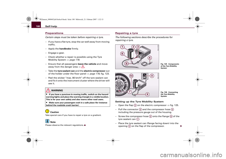
– Open the flap on the electric compressor ⇒fig. 125.
– Pull the connector and the compressor hose
including the pressure gauge out of the housing.
– Screw the compressor hose onto the flange of the
tyre sealant can .
– Place the tyre sealant can (flange facing down) into the
opening on the flap of the compressor.
Fig. 125 Components
of the Tyre Mobility
SystemFig. 126 Connecting
the Tyre Mobility
System
A2
A4
A5
A5
A6
A1
A3
document_0900452a816e6cc9.book Seite 180 Mittwoch, 21. Februar 2007 1:32 13
Page 183 of 210
Self-help181
Controls
Safety
Driving tips
General maintenance
Self-help
Technical data
– Unscrew the dust cap from the valve of the damaged
tyre.
– Screw the filler hose onto the valve ⇒page 180,
fig. 126.
– Insert the connector ⇒page 180, fig. 125 into the
cigarette lighter socket.
Inflating the tyre
–Move the switch ⇒page 180, fig. 126 on the
compressor
4) to position I. After 5 minutes tyre pressure
should be at least 1.8 bar.
– Switch off the compressor by moving switch to
position0. If the necessary tyre pressure of at least 1.8
bar is not reached please follow the instructions given in
the section Re-inflating the tyre.
Re-inflating the tyre
– Remove the filler hose from the valve and pull the
connector out of the socket.
– Slowly move the vehicle forwards and backwards about
10 metres. This enables the sealant to be distributed
more evenly.
– Remove the empty tyre sealant can and screw the
compressor hose ⇒page 180, fig. 125 directly onto
the valve.
– Insert the connector into the cigarette lighter socket.– Move the switch ⇒page 180, fig. 126 on the
compressor to position I. After 5 minutes tyre pressure
should be at least 1.8 bar.
– Switch off the compressor by moving switch to
position0. If the necessary tyre pressure of at least 1.8
bar is not reached this means that the tyre cannot be
repaired using the tyre sealant. You should obtain profes-
sional assistance.
Dismantling the Tyre Mobility System
– Remove the filler hose from the valve and pull the
connector out of the socket.
– Screw the dust cap onto the valve.
– Put the empty tyre sealant can back into its original pack-
aging and then secure it in the holder under the floor
panel in such a way that it will not leak.
– Then drive away immediately so that the tyre sealant can
spread evenly in the tyre.
WARNING
•
Please observe the manufacturers' safety notes on the stickers
on the compressor and the tyre sealant can.
•
If it was not possible to build up a tyre pressure of 1.8 bar
within 5 minutes this means that the tyre is too badly damaged.
Do not drive on.
•
Seek professional assistance if the repair of a tyre puncture is
not possible with the sealing compound.
4)The compressor should never be used for longer than 8 minutes.
A10
A7
A4
A8A5A4
A8
document_0900452a816e6cc9.book Seite 181 Mittwoch, 21. Februar 2007 1:32 13
Page 184 of 210
Self-help 182
Note•
Do not use the compressor for longer than 8 minutes at a time,
as it could overheat. When the compressor has cooled down, you
can use it again.
•
If tyre sealant should leak out, leave it to dry and then pull it off
like foil.
Final checkAfter covering a short distance it is necessary to check the
tyre pressure
– After about 10 minutes stop to check the tyre pressure.
– If tyre pressure is still at least 1.3 bar, pump the tyre up
to the pressure specified (see driver's door pillar) and
drive to the nearest workshop to have the tyre and the
tyre sealant can replaced.
– If tyre pressure is less than 1.3 bar, the tyre is too badly
damaged. Do not drive on. You should obtain profes-
sional assistance.
WARNING
If tyre pressure is less than 1.3 bar after driving about 10 minutes,
the tyre is too badly damaged. Do not drive on. You should obtain
professional assistance.
Note
After carrying out repairs to a tyre, have the tyre sealant can
replaced by a qualified dealer. This will ensure that the Tyre Mobility
System is operative again.
Changing a wheelTyres with directional tread pattern
Tyres with directional tread pattern must be mounted so
that they rotate in the correct direction.A directional tread pattern is identified by arrows on the sidewall
pointing in the forward running direction. Always note the direction
of rotation indicated when mounting the wheel. This is important so
that these tyres can give maximum grip and avoid excessive noise,
tread wear and aquaplaning.Applies to vehicles: with anti-theft wheel boltsAnti-theft wheel bolts
A special adapter is required to turn the anti-theft wheel
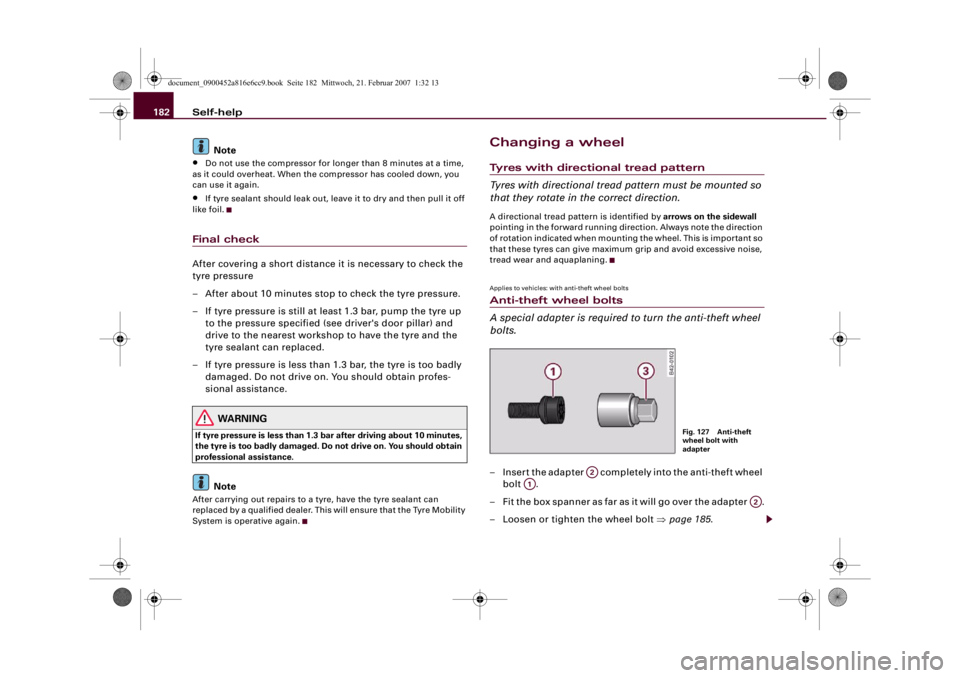
bolts.– Insert the adapter completely into the anti-theft wheel
bolt .
– F i t t h e b o x s p a n n e r as fa r as i t w i l l g o o v e r t h e a d a p t e r .
– Loosen or tighten the wheel bolt ⇒page 185.
Fig. 127 Anti-theft
wheel bolt with
adapter
A2
A1
A2
document_0900452a816e6cc9.book Seite 182 Mittwoch, 21. Februar 2007 1:32 13
Page 185 of 210
Self-help183
Controls
Safety
Driving tips
General maintenance
Self-help
Technical data It is advisable to carry the wheel bolt adapter in the vehicle. It should
be stored with the tool kit.
The code number of the anti-theft wheel bolt is stamped on the front
of the adapter. Your Audi R8 dealer will need this number to replace
the adapter if lost.
Note
Note the code number of the anti-theft wheel bolt and keep it in a
safe place – not in your vehicle.Applies to vehicles: with jackRaising the vehicle
The vehicle must be raised with a jack to remove the
wheel.
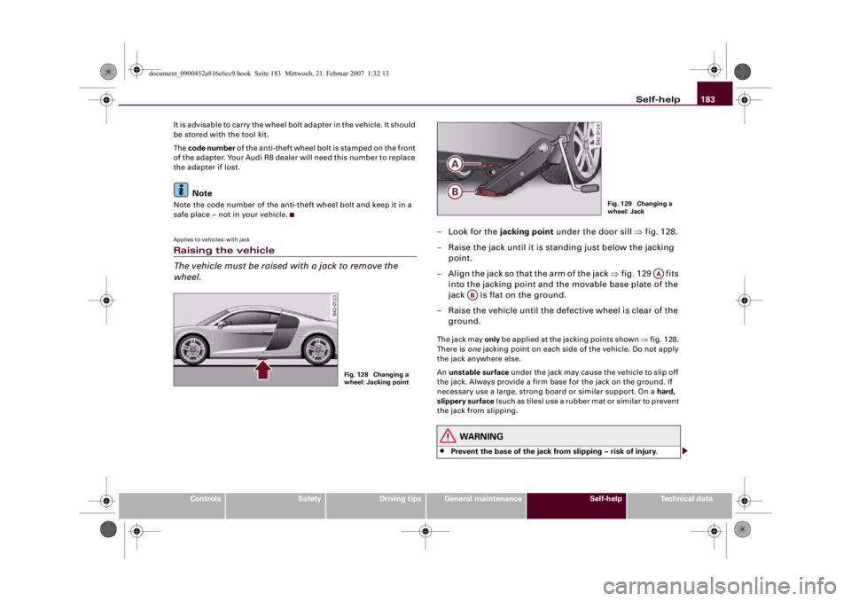
–Look for the jacking point under the door sill ⇒fig. 128.
– Raise the jack until it is standing just below the jacking
point.
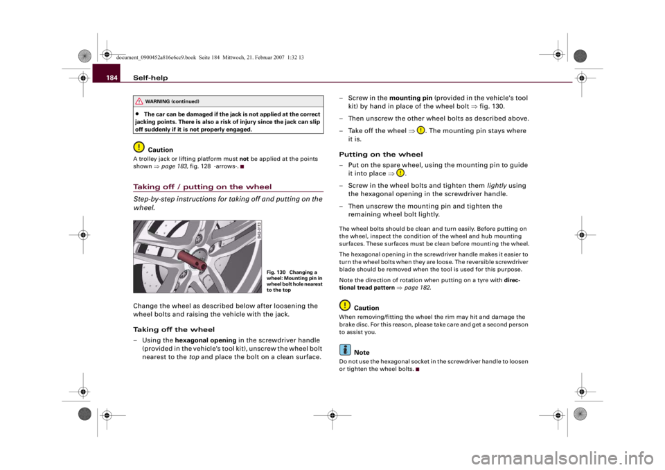
– Align the jack so that the arm of the jack ⇒fig. 129 fits
into the jacking point and the movable base plate of the
jack is flat on the ground.
– Raise the vehicle until the defective wheel is clear of the
ground.The jack may only be applied at the jacking points shown ⇒fig. 128.
There is one jacking point on each side of the vehicle. Do not apply
the jack anywhere else.
An unstable surface under the jack may cause the vehicle to slip off
the jack. Always provide a firm base for the jack on the ground. If
necessary use a large, strong board or similar support. On a hard,
slippery surface (such as tiles) use a rubber mat or similar to prevent
the jack from slipping.
WARNING
•
Prevent the base of the jack from slipping – risk of injury.
Fig. 128 Changing a
wheel: Jacking point
Fig. 129 Changing a
wheel: Jack
AA
AB
document_0900452a816e6cc9.book Seite 183 Mittwoch, 21. Februar 2007 1:32 13
Page 186 of 210
Self-help 184•
The car can be damaged if the jack is not applied at the correct
jacking points. There is also a risk of injury since the jack can slip
off suddenly if it is not properly engaged.Caution
A trolley jack or lifting platform must not be applied at the points
shown ⇒page 183, fig. 128 -arrows-.Taking off / putting on the wheel
Step-by-step instructions for taking off and putting on the
wheel.Change the wheel as described below after loosening the
wheel bolts and raising the vehicle with the jack.
Taking off the wheel
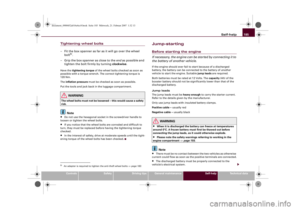
–Using the hexagonal opening in the screwdriver handle
(provided in the vehicle's tool kit), unscrew the wheel bolt
nearest to the top and place the bolt on a clean surface.–Screw in the mounting pin (provided in the vehicle's tool
kit) by hand in place of the wheel bolt ⇒fig. 130.
– Then unscrew the other wheel bolts as described above.
– Take off the wheel ⇒. The mounting pin stays where
it is.
Putting on the wheel
– Put on the spare wheel, using the mounting pin to guide
it into place ⇒.
– Screw in the wheel bolts and tighten them lightly using
the hexagonal opening in the screwdriver handle.
– Then unscrew the mounting pin and tighten the
remaining wheel bolt lightly.
The wheel bolts should be clean and turn easily. Before putting on
the wheel, inspect the condition of the wheel and hub mounting
surfaces. These surfaces must be clean before mounting the wheel.
The hexagonal opening in the screwdriver handle makes it easier to
turn the wheel bolts when they are loose. The reversible screwdriver
blade should be removed when the tool is used for this purpose.
Note the direction of rotation when putting on a tyre with direc-
tional tread pattern ⇒page 182.
Caution
When removing/fitting the wheel the rim may hit and damage the
brake disc. For this reason, please take care and get a second person
to assist you.
Note
Do not use the hexagonal socket in the screwdriver handle to loosen
or tighten the wheel bolts.
WARNING (continued)
Fig. 130 Changing a
wheel: Mounting pin in
wheel bolt hole nearest
to the top
document_0900452a816e6cc9.book Seite 184 Mittwoch, 21. Februar 2007 1:32 13
Page 187 of 210
Self-help185
Controls
Safety
Driving tips
General maintenance
Self-help
Technical data
Tightening wheel bolts– Fit the box spanner as far as it will go over the wheel
bolt
5).
– Grip the box spanner as close to the end as possible and
tighten the bolt firmly by turning clockwise.
Have the tightening torque of the wheel bolts checked as soon as
possible with a torque wrench. The correct tightening torque is
120 Nm.
The inflation pressure must be checked as soon as possible.
Put the tools and jack back in the luggage compartment.
WARNING
The wheel bolts must not be loosened – this would cause a safety
risk.
Note
•
Do not use the hexagonal socket in the screwdriver handle to
loosen or tighten the wheel bolts.
•
If you notice that the wheel bolts are corroded and difficult to
turn, they must be replaced before having the tightening torque
checked.
•
In the interest of safety, drive at moderate speeds until the tight-
ening torque of the wheel bolts has been checked.
Jump-startingBefore starting the engine
If necessary, the engine can be started by connecting it to
the battery of another vehicle.If the engine should ever fail to start because of a discharged
battery, the battery can be connected to the battery of another
vehicle to start the engine. Suitable jump leads are required.
Both batteries must be rated at 12 Volts. The capacity (Ah) of the
booster battery should not be significantly lower than that of the
discharged battery.
Jump leads
The jump leads must be heavy enough to carry the starter current.
Refer to the details given by the manufacturer.
Only use jump leads with insulated battery clamps.
Positive cable – usually red
Negative cable – usually black
WARNING
•
When it is discharged the battery can freeze at temperatures
around 0°C. A frozen battery must first be thawed out before
connecting the jump leads, as it could otherwise explode.
•
Please note the safety warnings referring to working in the
engine compartment ⇒page 155.Note
•
There must be no contact between the two vehicles as otherwise
current could flow as soon as the positive terminals are connected.
•
The discharged battery must be properly connected to the
vehicle's electrical system.
5)An adapter is required to tighten the anti-theft wheel bolts ⇒page 182.
document_0900452a816e6cc9.book Seite 185 Mittwoch, 21. Februar 2007 1:32 13
Page 188 of 210
Self-help 186•
Switch off the car telephone if necessary. Details will be given in
the manufacturer's instructions for the car telephone.
Starting the engine
The jump leads must be connected in the correct
sequence.The battery is located in the luggage compartment
⇒page 163. The luggage lid can be released manually if
necessary ⇒page 48.
Connecting the positive terminals with the
positive lead (red)
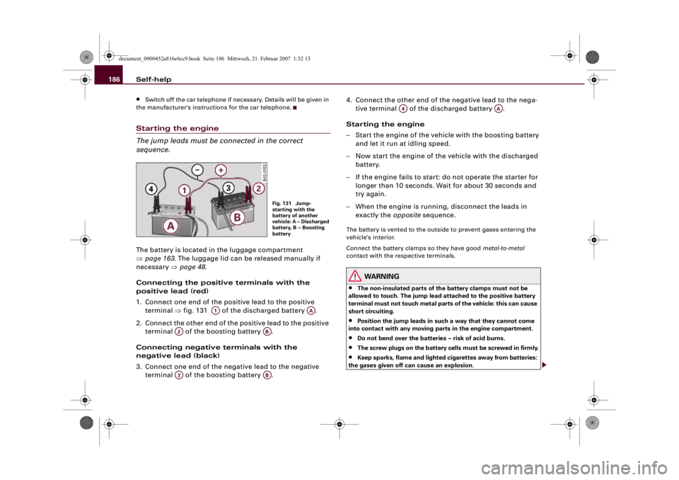
1. Connect one end of the positive lead to the positive
terminal ⇒fig. 131 of the discharged battery .
2. Connect the other end of the positive lead to the positive
terminal of the boosting battery .
Connecting negative terminals with the
negative lead (black)
3. Connect one end of the negative lead to the negative
terminal of the boosting battery .4. Connect the other end of the negative lead to the nega-
tive terminal of the discharged battery .
Starting the engine
– Start the engine of the vehicle with the boosting battery
and let it run at idling speed.
– Now start the engine of the vehicle with the discharged
battery.
– If the engine fails to start: do not operate the starter for
longer than 10 seconds. Wait for about 30 seconds and
try again.
– When the engine is running, disconnect the leads in
exactly the opposite sequence.
The battery is vented to the outside to prevent gases entering the
vehicle's interior.
Connect the battery clamps so they have good metal-to-metal
contact with the respective terminals.
WARNING
•
The non-insulated parts of the battery clamps must not be
allowed to touch. The jump lead attached to the positive battery
terminal must not touch metal parts of the vehicle: this can cause
short circuiting.
•
Position the jump leads in such a way that they cannot come
into contact with any moving parts in the engine compartment.
•
Do not bend over the batteries – risk of acid burns.
•
The screw plugs on the battery cells must be screwed in firmly.
•
Keep sparks, flame and lighted cigarettes away from batteries:
the gases given off can cause an explosion.
Fig. 131 Jump-
starting with the
battery of another
vehicle: A – Discharged
battery, B – Boosting
battery
A1
AA
A2
AB
A3
AB
A4
AA
document_0900452a816e6cc9.book Seite 186 Mittwoch, 21. Februar 2007 1:32 13
Page 189 of 210
Self-help187
Controls
Safety
Driving tips
General maintenance
Self-help
Technical data
Caution
Please note that the described method of connecting the leads is
meant for jump-starting your vehicle. If jump-starting another
vehicle, you should not connect the negative lead (–) to the negative
terminal of the discharged battery ⇒page 186, fig. 131 , but
directly to the engine block or a solid metal part bolted to the engine
block. If the battery of the other vehicle does not have a gas vent,
there is a risk that a mixture of oxygen and hydrogen gas can accu-
mulate and cause an explosion.Tow-starting and towing awayGeneral notes
Points to observe when tow-starting or towing awayIf you use a towrope:
Notes for the driver of the towing vehicle
– The towrope must be taut before driving off.
– Engage the clutch very gently when starting to move
(press the accelerator slowly if you have R tronic).
Notes for the driver of the towed vehicle
– The ignition should be switched on so that the turn
signals, horn, windscreen wipers and washers can be
used. Please ensure that the steering wheel is unlocked
when you switch on the ignition and that it moves freely.
– Put the gear lever in neutral or move the selector lever to
position N.– The brake servo and power steering only work when the
engine is running. Considerably more effort is required
on the brake pedal and steering wheel when the engine
is switched off.
– Ensure that the towrope remains taut at all times when
towing.
Towrope or towbar
It is easier and safer to tow a vehicle with a towbar. You should only
use a towrope if you do not have a towbar.
A towrope should be slightly elastic to reduce the loading on both
vehicles. It is advisable to use a towrope made of synthetic fibre or
similar material.
Attach the towrope or the towbar only to the towing anchorages
provided for this purpose ⇒page 188.
Driving technique
Towing requires some experience – especially when using a
towrope. Both drivers should be familiar with the technique required
for towing. Inexperienced drivers should not attempt to tow-start or
tow away another vehicle.
Do not pull too hard with the towing vehicle and take care to avoid
jerking the towrope. When towing on a loose surface there is always
a risk of overloading and damaging the anchorage points.
Caution
If there is no oil in the gearbox or no lubricant in the automatic
transmission the car may only be towed with the driven wheels
lifted clear of the road, or transported on a special car transporter
or trailer.
Note
•
Note the regulations concerning towing.
A4
document_0900452a816e6cc9.book Seite 187 Mittwoch, 21. Februar 2007 1:32 13
Page 190 of 210
Self-help 188•
The hazard warning lights of both vehicles must normally be
switched on. However, observe any regulations to the contrary.
•
Make sure that the towrope is not twisted, as otherwise the front
towline anchorage on your vehicle could work itself loose.
Front towline anchorage
The front towline anchorage is only mounted if the vehicle
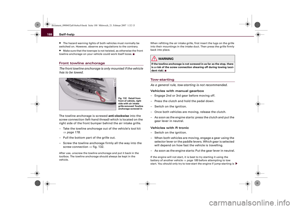
has to be towed.The towline anchorage is screwed anti-clockwise into the
screw connection (left-hand thread) which is located on the
right side of the front bumper behind the air intake grille.
– Take the towline anchorage out of the vehicle's tool kit
⇒page 178.
– Pull the bottom part of the grille out.
– Screw the towline anchorage firmly all the way into the
screw connection ⇒fig. 132.After use, unscrew the towline anchorage and put it back in the
toolbox. The towline anchorage should always be kept in the
vehicle.When refitting the air intake grille, first insert the lugs on the grille
into their mountings in the intake duct. Then press the grille firmly
back into place.
WARNING
If the towline anchorage is not screwed in as far as the stop, there
is a risk of the screw connection shearing off during towing (acci-
dent risk).Tow-starting
As a general rule, tow-starting is not recommended.Vehicles with manual gearbox
– Engage 2nd or 3rd gear before moving off.
– Press the clutch and hold the pedal down.
– Switch on the ignition.
– Once both vehicles are moving, release the clutch.
– As soon as the engine starts: press the clutch and put the
gear lever in neutral.
Vehicles with R tronic
– Switch on the ignition.
– When both vehicles are moving, engage a gear using the
selector lever or the paddle levers. Which gear is selected
will depend on how fast the vehicle is travelling.
– As soon as the engine starts: Put the gear lever in neutral.If the engine will not start, it is best to try starting it using the
battery of another vehicle ⇒page 185 before attempting to tow
start. You should only try to tow-start the engine if jump-starting is
Fig. 132 Detail from
front of vehicle, right
side with air intake
grille removed: Towline
anchorage screwed in
document_0900452a816e6cc9.book Seite 188 Mittwoch, 21. Februar 2007 1:32 13