AUDI R8 SPYDER 2014 Owners Manual
Manufacturer: AUDI, Model Year: 2014, Model line: R8 SPYDER, Model: AUDI R8 SPYDER 2014Pages: 244, PDF Size: 61.06 MB
Page 211 of 244

you should contac t you r authorized Audi
dealer imme diate ly to have the problem co r
rected.
- Do not use comme rcially ava ila ble tire seal
ants. Otherw ise, the electrical components
of the tire pressure monitoring system w ill
no l onger wor k properly and the sensor for
t h e tire pressure mo nitoring system will
hav e to b e replaced by a qualified wor kshop .
Tires and wheels 209
•
•
Page 212 of 244
210 What do I do now?
What do I do now?
Trunk escape handle
Appl ies to vehicles: wit h tru nk escape hand le
In case of an emergency, the front lid can be
opened from the inside using the trunk es
cape handle .
.,. To
open the front lid pu ll the handle.
The trunk escape handle inside the luggage
compartment is made of fluorescent material
to g low in the dark.
A WARNING
The trunk escape handle is to be used only
in an emergency.
Vehicle tool kit
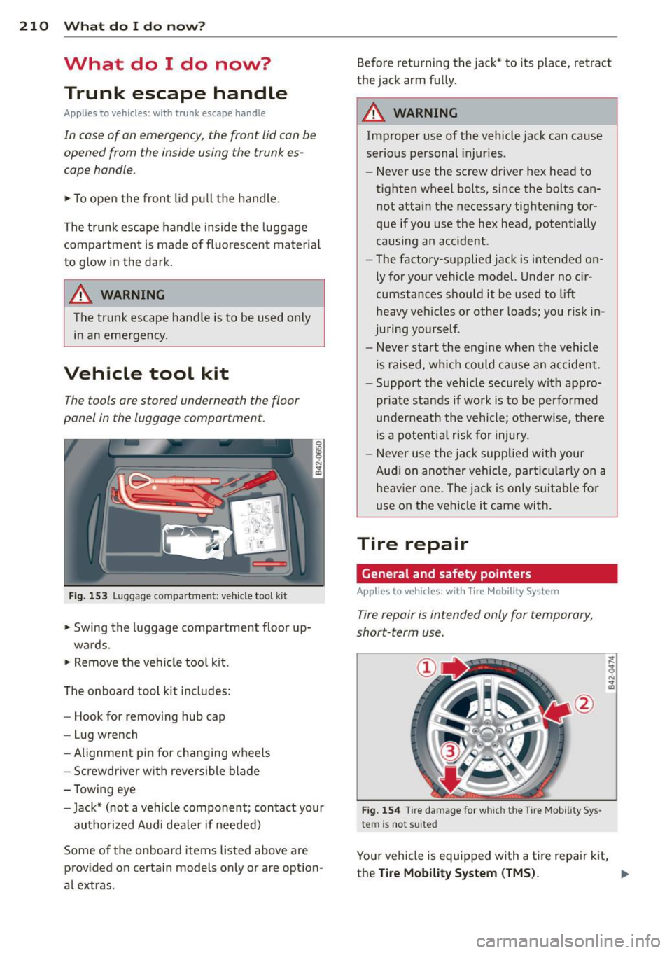
The tools are stored underneath the floor
panel in the luggage comportment.
Fig. 153 Luggage compartment: ve hicle tool k it
.,. Swing the luggage compartment floor up-
wards .
.,. Remove the vehicle tool kit.
The onboard tool kit includes:
- Hook for removing hub cap
- Lug wrench
- Alignment pin for changing wheels
- Screwdriver with reversible blade
- T owing eye
- Jack* (not a vehicle component; contact your
authorized Aud i dealer if needed)
Some of the on board items listed above are provided on certain models only or are option
a l extras. Before
returning the jack* to its place, retract
t h e jack arm fully.
A WARNING
-
Improper use of the vehicle jack can cause
serious personal injuries.
- Never use the screw driver hex head to
tighten wheel bolts, since the bolts can
not attain the necessary tightening tor
que if you use the hex head, potentially
causing an accident.
- The factory-supplied jack is intended on
ly for your vehicle model. Under no cir
cumstances should it be used to
lift
heavy veh icles or other loads; you risk in
juring yourself.
- Never start the engine when the vehicle
is raised, which could cause an acc ident.
- Support the vehicle securely with appro
priate stands if work is to be performed
underneath the vehicle; otherwise, there
is a potential risk for injury.
- Never use the jack supplied with your
Aud i on another vehicle, part icularly on a
heav ier one. The jack is only suitable for
use on the vehicle it came with.
Tire repair
General and safety pointers
Applies to veh icles: w it h Tire Mob ility System
Tire repair is intended only for temporary,
short-term use.
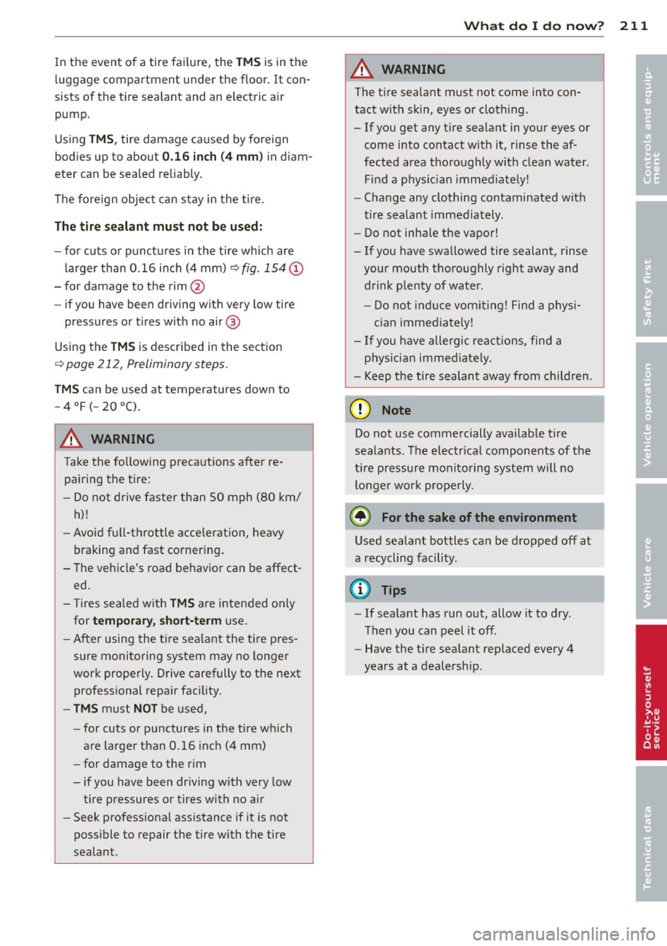
Fig . 154 Tire damage for wh ich the Tir e Mob ility Sys
te m is no t suited
Your vehicle is equipped with a tire repair kit,
the
Tire Mobility System (TMS). .,,.
Page 213 of 244
In the event of a tire fai lure, the TM S is in the
l uggage compartment under the floor . It con
sists of the tire sea lant and an electric a ir
pump.
Using
TM S, tire damage ca used by foreign
bodies up to about
0.1 6 inch (4 mm ) in diam
eter can be sealed reliab ly.
The foreign object can stay in the t ire.
The tir e sea lant must not be us ed :
- for cuts or punctu res in the tire which are
larger than 0.16 inch (4 mm)
r;;';> fig . 154 @
- for damage to the rim@
- if you have been driving w ith very low tire
pressures or tires with no air @
Using the
T M S is described in the section
¢ page 212, Preliminary steps.
TM S can be used at temperatures down to
-4 °F ( -20 °().
8_ WARNING
Take the following precautions after re
pairing the tire:
-
- Do not drive faster than 50 mph (80 km/
h)!
- Avoid full-throttle acce leration, heavy
braking and fast cornering.
- The vehicle's road behavior can be affect ed.
- Tires sealed with
TMS are intended only
for
tempora ry, short-te rm use .
- After using the t ire sea lant the ti re p res
sure monitoring system may no longer
work properly. Drive carefully to the next professional repair fac ility.
- TMS must NO T be used,
- for cuts or punctures in the tire which
are larger than 0.16 inch (4 mm)
- for damage to the rim
- if you have been dr iv ing with very low
tire pressures or tires with no air
- Seek profess ional assistance if it is not
poss ible to repair the tire with the tire
sealant.
What do I do now? 211
8_ WARNING
The tire sealant must not come into con
tact with skin, eyes or clothing.
- If you get any tire sealant in your eyes or
come into contact with it, rinse the af
fected area thoroughly with clean water .
Find a phys ician immed iately!
- Change any clothing contaminated wit h
tire sealant immediately.
- Do not inhale the vapor!
- If you have swallowed tire sealant, rinse your mouth thoroughly right away and drink plenty of water .
- Do not indu ce vomit ing! Find a physi
c ian immediately!
- I f you have allergic react ions, find a
phys ician immediately.
- Keep the tire sealant away from children.
(D Note
Do not use commercially available tire
sealants . The electr ical components of the
tire pressure monitoring system will no
l onge r work properly.
@ For the sake of the env ironment
Used sealant bottles can be dropped off at
a recycling facility .
(D Tips
-If sealant has run out, allow it to dry .
Then you can peel it off.
- Have the t ire sealant replaced every 4
years at a dealership .
• -
•
Page 214 of 244
212 What do I do now?
Preliminary steps
Applies to vehicles: with T ire Mobility System
Some preliminary steps are necessary for tire
repair .
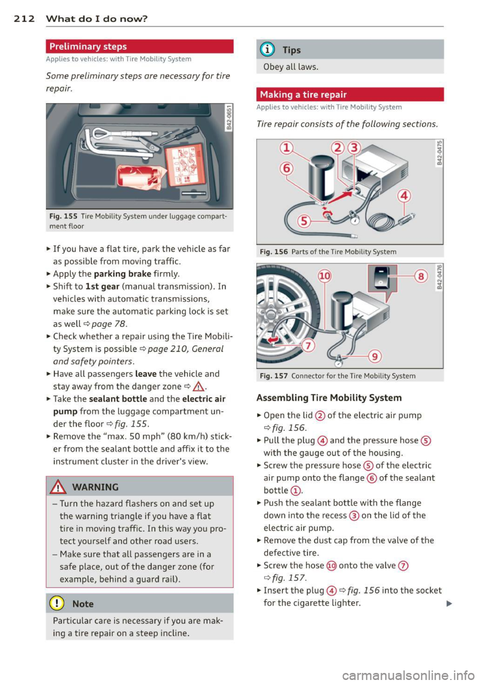
Fig. 155 Tire Mobili ty System under luggage co mpart
ment f loor
.,. If you have a flat tire, park the vehicle as far
as possible from mov ing traffic .
.,. Apply the
park ing brake firmly .
.,. Shift to
1st gear (manual transmission) . In
vehicles with a utomat ic transm iss ions,
make sure the automatic parking lock is set
as well
c::> page 78 .
.,. Check whether a repair using the Tire Mobili
ty System is possible
c::> page 210, General
and safety pointers .
.,. Have all passengers leave the vehicle and
stay away from the danger zone
c::> .&, .
.,. Take the sealant bottle and the electric air
pump from the luggage compartment un
der the floor
c::> fig. 155.
.,. Remove the "max. 50 mph" (80 km/h) stick
er from the sealant bottle and affix it to the
instrument cluster in the driver 's view.
A WARNING
- Turn the hazard flashers on and set up
the warning triangle if you have a flat
tire in moving traff ic. In this way you pro
tect you rs elf and other road users.
- Make sure that all passengers are in a
safe place, out of the danger zone (for
example, behind a guard ra il).
(D Note
Particular care is necessary if you are mak
ing a tire repair on a steep incline.
-
(D Tips
Obey all laws.
Making a tire repair
Applies to vehicles: with Tire Mobility System
Tire repair consists of the following sections.
Fig. 156 Parts of the Ti re Mobility System
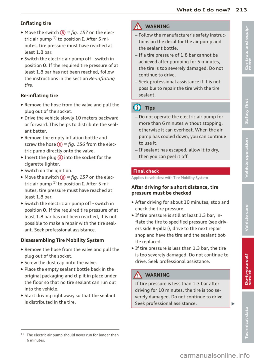
Fig. 157 Conn ector for the Tire Mob i,lity System
Assembling Tire Mobility System
.,. Open the lid @of the electric air pump
c::> fig. 156 .
.,. Pull the plug© and the pressure hose ®
w ith the gauge out of the housing.
.,. Screw the pressure hose ® of the electric
air pump onto the flange @ of the sealant
bottle @.
.,. Push the sealant bott le w ith the flange
down into the recess @ on the lid of the
electric air pump.
.. Remove the dust cap from the valve of the
defective tire.
.. Screw the hose @onto the valve
(j)
c::>fig. 157.
.,. Insert the plug© c::> fig. 156 into the socket
for the cigarette lighter. .,,_
Page 215 of 244
Inflating tire
"' Move the switch @¢ fig. 157 on the elec
tric air pump
ll to posit ion I. After 5 mi
nutes, tire pressure must have reached at
l east 1.8 bar .
"' Switch the electric a ir pump off - switch in
position
0 . If the required tire pressure of at
least 1.8 bar has not been reached, follow
the instructions in the section
Re -inflating
tire .
Re-infl ating tire
"' Remove the hose from the valve and pu ll the
plug out of the socket.
"' Drive the vehicle slowly 10 meters backward
or forward. This helps to distribute the seal
ant better.
"' Remove the empty inflat ion bottle and
sc rew the hose ®¢
fig. 156 from the elec
tric pump directly onto the va lve.
"' Insert the plug @ into the socket for the
cigarette lighter .
"' Switch on the ignition.
"' Move the switch @¢
fig. 157 on the elec
tric a ir pump
l) to posit ion I. After 5 mi
nutes, t ire pressure must have reached at
least 1.8 bar.
"' Switch the electric a ir pump off - switch in
pos ition
0 . If the requ ired t ire pressu re of at
l east 1.8 ba r has not been reached, it is not
possible to make a repair with the tire seal
ant . Seek professional assistance .
Disassembling Tire Mobility System
"'Remove the hose from the valve and pu ll the
plug out of the soc ket.
"' Screw the dust c ap onto the va lve.
"' Place the empty sealant bottle back in the
o riginal packaging and clip it in p lace under
the floor so that no tire sealant can run out into the vehicle.
"' Start driving right away so that the sealant
is d istributed in the tire.
l ) The e lectr ic a ir pu mp sho uld never r un for lo nge r th an
6 m in utes .
What do I do now? 213
A WARNING
-Follow the manufacturer's safety instruc
tions on the decal for the air pump and
the sealant bottle.
- If a tire pressure of 1.8 bar cannot be
achieved after pumping for 5 minutes,
the t ire is too severe ly damaged . Do not
continue to dr ive.
- Seek professional ass istance if it is not
possible to repa ir the tire w ith the t ire
sealant.
(D Tips
- Do not operate the electric air pump for
more than 6 minu tes witho ut stopping,
otherwise it can overheat . When the a ir
pump has coo led down, you can continue
to use it.
- I f sea lant has escaped, allow it to dry,
t hen yo u can peel it off.
Final check
App lies to vehicl es: wi th Tire Mobility Sy stem
Aft er driv ing for a short distance, tire
pre ssure must be chec ked
"' After driving for about 10 min utes, stop and
check the tire pressure.
"' If tire pressure is st ill at least 1.3 bar, in
flate the tire to specified pressure (see dr iv
er's side B-pillar), drive to the next repa ir
shop and have the tire and the sealant bot
tle replaced .
"'I f ti re pressu re is less than 1.3 ba r, the t ire
is too severely damaged. Do not con tinue to
drive . See k professiona l assist ance.
A WARNING
=
If t ire press ure is less than 1.3 bar after
driving for 10 minutes, the tire is too se
verely damaged. Do not cont in ue to drive.
Seek professional ass istance.
-
•
•
Page 216 of 244
214 What do I do now ?
@ Tips
After a tire repair, have the sealant bottle
rep laced at a dealership. This restores full
functionality to the Tire Mob ility System.
What should I be
aware of when
changing a tire?
Tires with unidirectional tread design
Tires with unidirectional tread design must be
mounted with their tread pattern pointed the
right direction .
A unidirectiona l tire can be ident ified by ar
row s on the sidewall,
which point in the direc
tion of the rotation. You must follow the
specified direction of rotat ion. This is necessa
ry in order for these t ires to develop the ir op·
timum characteristics regarding grip, road noise, wear, and hydroplani ng.
Anti-theft wheel bolts
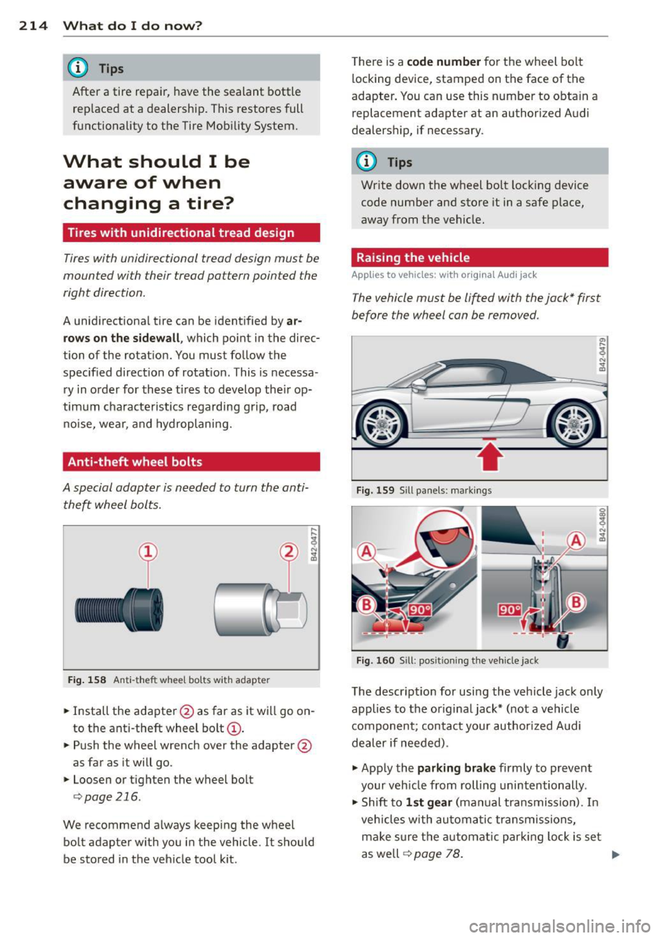
A special adapter is needed to turn the anti· theft wheel bolts.
Fi g. 1 58 Anti-theft wheel bolts with adapter
., Install the adapter @as far as it wi ll go on
to the ant i-theft wheel bolt(!).
., Push the wheel wrench over the adapter @
as far as it wi ll go.
., Loosen or tighten the wheel bo lt
r=> page 216.
We recommend a lways keeping the wheel
bolt adapter w ith you i n the vehicle. It should
be stored in the veh icle tool k it. T
he re is a
c ode number for the wheel bo lt
locking device , stamped on the face of the
adapter . You can use this n umber to obta in a
replacement adapter at an authorized A udi
dealers hip, if necessary.
(0 Tips
Wr ite down the wheel bolt lock ing device
code number and store it in a safe place,
away from t he vehicle.
Raising the vehicle
Applies to vehicles: with orig inal Audi jack
The vehicle must be lifted with the jack* first
before the wheel can be removed.
•
F ig. 159 Sill panels: ma rk in gs
Fi g. 16 0 Sill: pos it io nin g th e ve hicle jack
The descr ip ti on for using the vehicle jack only
applies to the origina l jack* (not a vehicle
component; contact your author ized A udi
dealer if nee ded) .
., App ly the
parking brake firmly to prevent
your veh icle from rolling unintentionally.
., Shift to
1st gear (manual transmission). In
veh icles with au toma tic tra nsmissions,
make sure t he au tomatic par king lock is se t
as well
r=> page 78 . ..,
Page 217 of 244
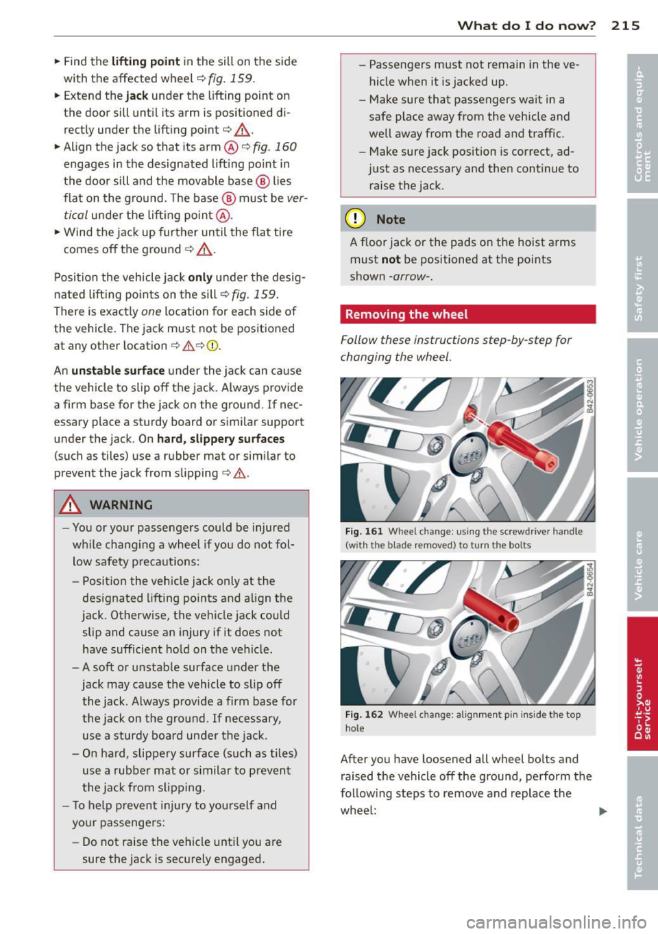
.. Find the lifting p oint in the sill on the side
with the affected wheel¢
fig. 159.
.. Extend the ja ck under the lifting point on
the doo r sill unti l its arm is positioned di
rectly under the lifting point¢ &_ .
.. Align the jack so that its arm @¢
fig. 160
engages in the designated lifting point in
the door sill and the movable base @ lies
flat on the ground. The base @ must be
ver
tical
under the lift ing po int @ .
.. Wind the jack up further until the flat tire
comes off the ground¢&_ .
Position the vehicle jack
onl y under the desig
nated lift ing po ints on the sill¢
fig. 159.
There is exactly one location for each side of
the vehicle. The jack must not be pos itioned
at any other location ¢ fri. ¢0 .
An
un sta bl e s urfa ce u nder the jack can cause
the vehicle to s lip off the jack . Always provide
a firm base for the jack on the ground . If nec
essary plac e a sturdy board or similar support
under the jack. On
ha rd, slippe ry surface s
(such as tiles) use a rubber mat or sim ilar to
prevent the jack from slipping¢&. .
A WARNING
-You or your passengers could be injured
wh ile chang ing a wheel if you do not fol
low safety p re ca utions:
- Position the vehicle jack only at the
designated lifting points and align the
jack . Otherwise, the vehicle jack could
slip and cause an injury if it does not
have sufficient ho ld on the vehicle.
- A soft or unstable surface under the
jack may cause the vehicle to slip off the jack. Always provide a firm base for
the jack on the ground . If necessary,
use a sturdy boa rd under the jack.
- On ha rd, slippery surface (such as tiles)
use a rubber mat o r similar to prevent
the jack from slipping .
- To help prevent injury to yourself and
your passenge rs:
- Do not raise the vehicle unti l yo u are
sure the jack is securely engaged .
What do I do now ? 215
-Passengers must not remain in the ve
hicle when it is jacked up .
- Make sure that passengers wait in a
safe place away from the veh icle and
well away from the road and traffic .
- Make sure jack position is correct, ad
just as necessary and then cont inue to
raise the jack .
(D Note
A floor jack or the pads on the hoist arms
must
not be positioned at the points
shown
-arrow -.
Removing the wheel
Follow these instructions step -by-step for
changing the wheel .
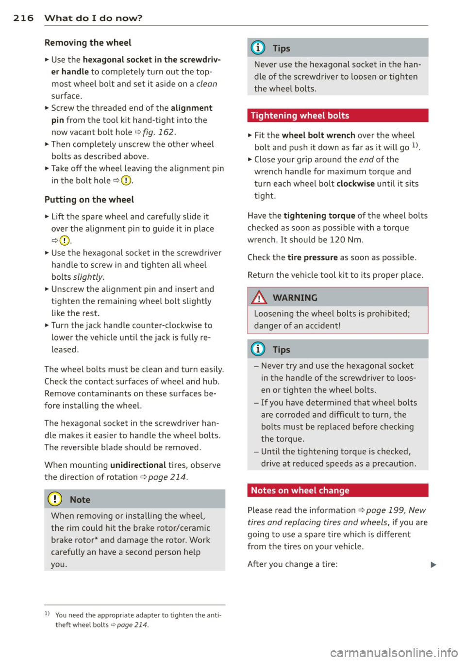
Fig . 1 61 W hee l change: us ing the sc rewdr iver hand le
(w it h th e blade r emov ed) to t urn th e bolts
F ig . 1 62 Whee l change: alignmen t pin inside the top
h ol e
After you have loosened all wheel bo lts and
raised the vehicle off the grou nd, perform the
follow ing steps to remove and replace the
whee l: ..,.
Page 218 of 244
216 What do I do now?
Removing the wheel
.. Use the hexagonal socket in the screwdriv
er handle
to comp letely turn out the top
most wheel bolt and set it aside on a
clean
sur face .
.. Screw the threaded end of the
alignment
pin
from the tool kit hand-tight into the
now vacant bolt hole
o fig. 162.
.. Then completely unscrew the other wheel
bolts as described above .
.. Take off the wheel leav ing the alignment pin
in the bolt hole
o(D .
Putting on the wheel
.. Lift the spare wheel and carefully slide it
over the alignment pin to guide it in place
o@.
.. Use the hexagonal socket in the screwdr iver
handle to screw in and tighten all wheel
bolts
slightly .
.. Unscrew the alignment pin and insert and
tighten the remaining whee l bolt slig htly
like the rest.
.. Turn the jack handle counter-clockw ise to
lower the vehicle until the jack is fully re
leased .
The wheel bolts must be clean and turn easily.
Check the contact surfaces of wheel and hub. Remove contaminants on these surfaces be
fore installing the wheel.
The hexagonal socket in the screwdriver han
dle makes it easier to handle the wheel bolts.
The reversible blade should be removed.
When mounting
unidirectional tires, observe
the direction of rotation
o page 214.
«I) Note
When removing or installing the wheel,
the rim could hit the brake rotor/ceramic
brake rotor* and damage the rotor. Work
carefully an have a second perso n he lp
you .
1l You need the appropriate adapte r to tigh ten the anti
theft whee l bo lts
c:> page 214.
(D Tips
Never use the hexagonal socket in the han
dle of the screwdriver to loosen or tighten
the wheel bo lts.
Tightening wheel bolts
.. Fit the wheel bolt wrench over the wheel
bolt and push it down as far as it will go
ll.
.. Close your grip around the end of the
w rench handle for maximum torque and
turn each wheel bolt
clockwise until it sits
tight .
Have the
tightening torque of the wheel bolts
checked as soon as possible with a to rque
wrench. It should be 120 Nm .
Check the
tire pressure as soon as possible.
Return the veh icle tool k it to its proper place.
A WARNING ..,___
Loosening the wheel bolts is prohibited;
danger of an acc ident!
(D Tips
- Never try and use the hexagonal socket
in the handle of the screwdriver to loos
en or t ighten the wheel bo lts.
- If you have determined that wheel bolts are corroded and difficult to turn, the
bolts must be replaced before check ing
the torque .
- Until the t ightening torque is checked,
dr ive at reduced speeds as a precaution.
Notes on wheel change
-
Please read the information o page 199, New
tires and replacing tires and wheels,
if you are
go ing to use a spa re tire wh ich is different
from the tires on your vehicle.
After you change a tire:
Page 219 of 244

-Che ck the tire p re ss ure on the spare imme
diatel y afte r mounting.
- Hav e the wheel b olt tightening torque
checked with a torque wrench a s soon a s
possib le by you r auth orized Audi dealer or
a qu alified ser vice sta tio n.
- With steel and allo y w heel rim s, the wheel
bolts are correctl y tight ened at a to rq ue of
90 ft lb (1 20 Nm ).
- If yo u notice while changin g a ti re th at the
wheel bolts are co rrod ed and diff icult to
turn , then they should be repl aced before
y ou check the t ighten ing to rqu e.
- Replace the flat t ire with a new one and
ha ve it installed on your vehicle as soon as
possib le . R emount th e wh eel co ver .
Until then, driv e with extra care and at re
d uced speeds.
A WARNING
- If you are going to equip your vehicle
with t ires or rims wh ich differ from those
w hich were factory installed, then be
sure to read the informat ion
~page 199,
New tires and replacing tires and
wheels.
- Always store the tools securely in lug
gage compa rtment. Otherw ise, in an ac
c ident o r sudden mane uver they could fly
f orward, causing inju ry to passengers in
the vehicle .
(D Note
Do not use commerc ia lly available t ire
sealants. Othe rwise, the elec trical compo
nents of the tire pressure monitoring sys
tem* will no longer work properly and the
sensor for the tire pressure monitoring
system wi ll have to be replaced by a qua li
fied workshop.
What do I do now? 217
Jump-starting
General
If necessary, the engine can be started by
connecting it to the battery of another vehi
cle.
If the engine should fail to start because of a
discharged or weak battery, the battery can be
connected to the battery of
another vehicle,
us ing a
pair of jump er cabl es to start the en
gine.
Both batteries must be rated at 12 volts . The
capacity (Ah) of the booster battery must not
be substantia lly less than the capac ity of the
discharged battery .
Jumper cables
Use only jumper cables of suff ic ient ly large
cro ss se ction to safely car ry the starter cur
rent . Refer to the manufacturer's specifica
tions .
Use only jumper cab les which have
insulated
term inal clamps and are properly marked for
dist inction:
plu s(+) cable : in most cases colored r ed
m inu s(-) cable :
in most cases colored black
A WARNING ~
Batteries contain e lectric ity, acid, and gas .
Any of these can cause very serious or fata l
injury. Follow the instructions below for
safe handling of your vehicle's battery.
-Always shield your eyes and avo id lean-
ing over the battery whenever poss ible.
- A discharged battery can a lready freeze
at temperatures just below 32 °F (0 °(). Before connect ing a jumper cable , the
frozen battery must be thawed com
pletely, othe rwise it could explode .
- Do not allow battery acid to contact eyes
or skin . Flush any contacted area with
wate r immediately .
- Improper use of a booster battery to
start a vehicle may cause an explosion. •
•
Page 220 of 244

218 Wh at do I do now ?
-Vehicle batteries generate explos ive gas
es. Keep sparks, flame and lighted ciga
rettes away from batteries.
- Do not try to jump start any vehicle with
a low acid level in the battery.
- The voltage of the booster battery must
also have a 12-Volt rating. The capacity
(Ah) of the booster battery should not be
lower than that of the discharged bat
tery. Use of batteries of different voltage or substant ially different "Ah" rating
may cause an explos ion and personal in
Jury.
- Never charge a frozen battery. Gas trap
ped in the ice may cause an explosion.
- Never charge or use a battery that has
been frozen. The battery case may have
be weakened.
- Use of batteries of different voltage or
substant ially different capacity (Ah) rat
ing may cause an explosion and injury.
T he capacity (Ah) of the booster battery
should not be lower than that of the dis
charged battery.
- Before yo u check anything in the engine
compartment, always read and heed all
WARNINGS ¢
page 172, Working in the
engine compartment.
(D Note
- Applying a higher vo ltage booster bat
tery wi ll ca use expensive damage to sen
sitive electronic components, s uch as
control units, relays, radio, etc.
- There m ust be no e lectrica l contact be
tween the vehicles as otherwise current
could already start to flow as soon as the
positive(+) terminals are connected .
(0 Tips
-The discharged battery must be proper ly
connected to the vehicle's electrical sys
tem.
- Switch off any car phone, or follow the
car phone instructions for this situation.
Use of jumper cables
Make sure to connect the jumper cable
clamps in exactly the order described below!
F ig . 1 63 Luggage compartment: co nnectors for a
charge r and jump start cables
Fi g. 1 64 Jump start us ing the battery in a nother vehi
cle: A· Fema le socket, B • D isc harge
The battery is located in the luggage compart
ment¢
page 185. T he front lid can be opened
i n an emergency¢
page 34.
Do not connect the negative cable d irectly to
the negative term inal on the battery. Connect
it to a
jump st a rt pin instead ¢ fig. 163.
Connect the po sitive cable (red ) to the
positive terminal
1. Co nnect one end of the red jumper cable
¢
fig . 164 (!) to the positive terminal of
discharged battery @.
2 . Connect the other end of the red jumper
cable to the positive terminal @of the
booster battery @.
Connect the n egativ e cable (black ) to the
n egati ve terminal
3. Connect one end of the b lack jumper ca
ble @ to the negative terminal of the
booster battery @. .,.