oil temperature AUDI RS7 SPORTBACK 2016 Owners Manual
[x] Cancel search | Manufacturer: AUDI, Model Year: 2016, Model line: RS7 SPORTBACK, Model: AUDI RS7 SPORTBACK 2016Pages: 282, PDF Size: 70.78 MB
Page 22 of 282
Instruments and indicator lights
For more information ¢page 28.
!?) Engine speed limitation
(II Maximum engine speed XXXX rpm
The engine speed is automatically limited to the
speed displayed in the instrument cluster. This
protects the engine from overheating.
The engine speed limitation deactivates once the
engine is no longer in the critical temperature
range and you have released the accelerator ped
al.
If the engine speed limitation was activated by
an engine control malfunction, the~ indicator
light also turns on. Make sure the engine speed
does not go above the speed displayed, for exam
ple when downshifting. Drive to an authorized
Audi dealer or authorized Audi Service Facility im
mediately to have the malfunction corrected.
(D Tips
The engine speed is limited when the engine
is cold -the full engine output is not availa
ble. When the engine is at operating temper
ature, the red area in the tachometer moves
to a higher RPM range .
-Engine oil sensor
• Oil level! Sensor defective
If the symbol illuminates, contact your author
ized Audi dealer and have the oil sensor inspect
ed. Until you have this done, check the oil level
each time you refuel just to be on the safe side
¢page 207 .
f Engine warm-up request
n Please warm up engine
Fuel has entered the engine oil, either from low
outside temperatures or frequent short drives.
Drive until the engine is warm so that the fuel in
the engine oil will evaporate . Avoid high engine
speeds, full accelerating and heavy engine loads
when doing this.
20
~ Fuel tank system
II] Please refuel
If the indicator light turns on for the first time
and the message appears , there are about 2.6
gallons (10 liters) of fuel left in the tank .
111 Fuel tank system malfunction! Please con
tact dealer
There is a malfunction in the fuel tank system.
Drive to an authorized Audi dealer or authorized
Audi Service Facility immediately to have the
malfunction corrected.
(D Tips
More information on refueling is available on
page
¢ page 199.
· <9 Washer fluid level
g, "$ Please refill washer fluid
Fill the washer fluid for the windshield washer
system and the headlight washer system* when
the ignition is switched off ¢
page 216.
• Windshield wipers
m Windshield wiper defective
There is a malfunction with the windshield wip
ers.
Drive to an authorized Audi dealer or authorized
Audi Service Facility immediately to have the
malfunction corrected.
~ /0* Defective light bulb warning
If the J:i indicator light turns on, a light has
failed. The message indicates the location of the
light. If the
I) indicator light also turns on, then
a rear fog light has failed. The position of the in
dicator light corresponds with the location on the
vehicle .
Drive to an authorized Audi dealer or authorized
Audi Service Facility immediately to have the malfunction corrected .
Vehicle lights: Malfunction
Page 23 of 282
There is a malfunction in the headlights or the
light switch.
Drive to an authorized Audi dealer or authorized
Audi Service Facility immediately to have the
malfunction corrected.
i,CD Headlight range control
II Headlight range control: defective!
If the symbol illuminates, the headlight range
control is no longer working properly. Have the
system checked and repaired at your Audi dealer.
§0 Adaptive Light
Applies to: veh icles with Adapt ive Light
miJ Audi adaptive light: system fault
If the indicator light turns on and this message
appears, there is a malfunction in the adaptive
light system . The headlights still function.
Go to an authorized dealership to have the head
lights or the control unit for the Adaptive Light
repaired.
@) Light/rain sensor
!'al Automatic headlights/ automatic wipers:
System fault
The light/rain sensor is malfunctioning .
For safety reasons, the low beams are turned on
permanently with the switch in
AUTO. However,
you can continue to turn the lights on and
off us
ing the light switch. You can still control all func
tions that are independent of the rain sensor
through the windshield wiper lever.
Drive to an authorized Audi dealer or authorized
Audi Service Facility immediately to have the
malfunction corrected.
; Adaptive dampers
Applies to: veh icles with adaptive dampers
;:::: R Suspension: System fault! You can continue
t3 driving
'SI: ,....,
~ There is an adaptive damper malfunction.
N v:, ,....,
Instruments and indicator lights
Drive to an authorized Audi dealer or authorized
Audi Service Facility immediately to have the
malfunction corrected.
I- : Sport differential
Applies to: vehicles wit h spo rt differential
Ill Sport differential: system fault
There is a malfunction with the sport differential.
Drive to your authorized Audi dealer immediately
to have the malfunction corrected.
Ill Sport differential: overheating
The transmission temperature has increased sig
nificantly due to the sporty driving manner. Drive
in a less sporty manner until the temperature re
turns to the normal range and the indicator light
switches of.
,8. WARNING
-
Contact your authorized Audi dealer or a
qualified workshop if the sport differential is
faulty or malfunctioning. The repair must be
performed
by trained personnel using the cor
rect oil in order to ensure safety.
¢ Q Turn signals
The indicator light blinks when you use either
turn signal.
Whenever you use the left B or the rig ht Ill
turn signal, the indicator light blinks. When you
use the emergency flashers, both indicator lights
flash.
If one of the turn signal light bulbs burn out, the
turn signal will blink twice as fast as normal.
Carefully drive to your authorized Audi dealer im
mediately to have the malfunction corrected.
(D Tips
For more information on the turn signals, re
fer to
~ page 44.
21
Page 24 of 282
Instruments and indicator lights
CRUISE /11
(') Cru ise control
The warning/indicator light ltj;\9~1@ (USA models)/
El (Canada models) illuminates when the cruise
control is activated ¢
page 77.
Driver information
system
Overview
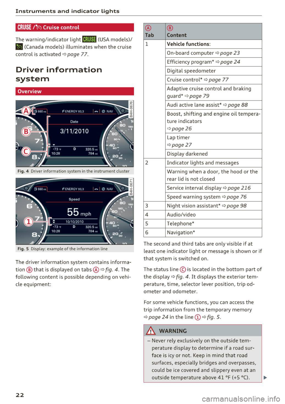
Fig. 4 Driver informat ion system in the instrument cluster
Fig. S Disp lay: example of the in formation lin e
The driver information system contains informa·
tion @ that is displayed on tabs@¢
fig. 4. The
following content is possible depend ing on veh i
cle equipment:
22
@ ®
Tab Content
1 Vehicle functions :
On-board computer¢ page 23
Efficiency program*¢ page 24
Digital speedometer
Cruise control* ¢
page 77
Adaptive cruise control and braking
guard* ¢
page 79
Audi active lane assist* ¢ page 88
Boost, shifting and engine oil tempera-
ture indicators
¢page26
Lap timer
¢page 27
Display darkened
2 Indicator lights and messages Warning when a door, the hood or the rear lid is not closed
Service interval display
¢page 216
Speed warning system~ page 76
3 Night vision assistant* ¢ page 98
4 Audio/video
s Telephone*
6 Nav igat ion*
The second and third tabs are only visible if at
least one indicator light or message is shown or if
that system is switched on.
The status line © is located in the bottom part of
the display¢
fig. 4 . It displays the exterior tern·
perature, time, selector lever position, tripod·
ometer and odometer.
Fo r some vehicle functions, you can access the
trip information from the temporary memory
¢
page 24 i n the line©¢ fig. 5.
&_ WARNING
- Never rely exclusively on the outside tern·
perature display to determine if a road sur
face is icy or not. Keep in mind that road
surfaces, especially bridges and overpasses,
could be ice covered and slippery even at an
-
outside temperature above 41 °F ( +S 0
(). ~
Page 28 of 282
Instruments and indicator lights
Head-up display
Applies to: vehicles with Head-up display
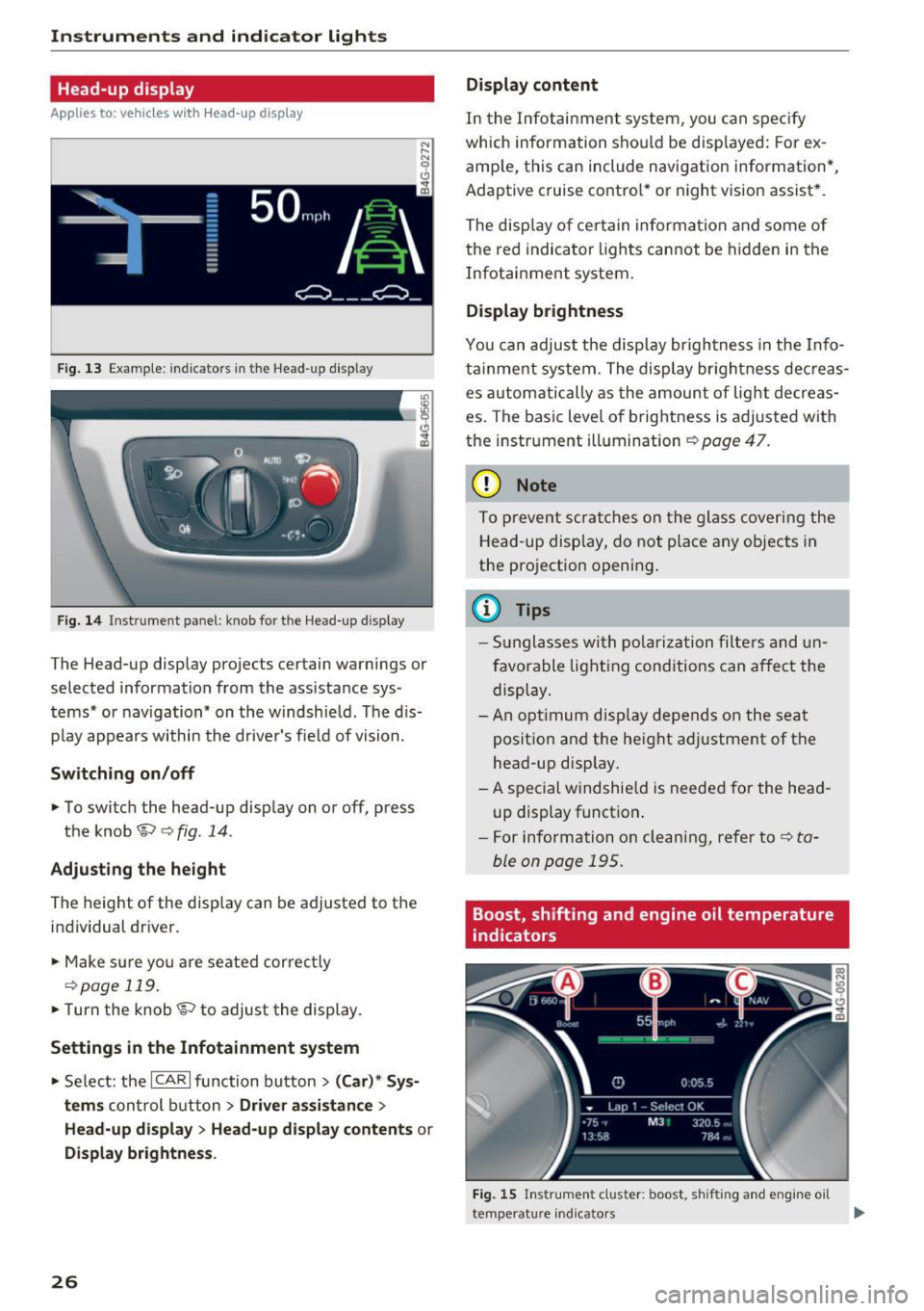
Fig. 13 Example: indicators in the Head-up display
F ig. 14 Inst rument panel: knob for the Head-up display
The Head-up display projects certain warnings or
selected information from the ass istance sys
tems* or navigation* on the windshie ld. The d is
p lay appears within the driver's fie ld of vision.
Switching on/off
• To switch the head-up disp lay on or off, press
the knob~
c:> fig. 14.
Adjusting the height
The height of the display can be adjusted to the
individual driver.
• Make sure yo u are seated correct ly
c:> page 119.
• Turn the knob~ to adjust the display.
Settings in the Infotainment system
• Select: the ICAR I function bu tton > (Car)* Sys
tems
control b utton > Driver assistance >
Head-up displ ay> Head-up di splay contents or
Display brightness .
26
Display content
In the Infotainment system, you can spec ify
which information shou ld be disp layed: For ex
amp le, this can include navigation information*,
Adaptive cruise contro l* or night vision assist *.
The display of certain information and some of
the red indicator lights cannot be hidden in the
Infotainment system.
Display brightness
You can adjust the display brightness in the Info
ta inment system . The display br ightness dec reas
es automatically as the amount of light decreas
es . The basic leve l of brightness is adjusted with
the instrument illumination
c:> page 47.
(D Note
To prevent scratches on the glass covering the
Head-up display, do not place any objects in
the projection opening.
(D Tips
- Sunglasses with polarization filters and un
favorable lighting conditions can affect the
display.
- An optimum display depends on the seat
position and the height adjustment of the
head-up display.
- A special windshie ld is needed for the head
up display function .
- For information on cleaning, refer to
c:> ta
ble on page 195.
Boost, shifting and engine oil temperature
indicators
Fig. 15 Instrument cluster: boost, shifting and engine oil
temperature indicators
Page 29 of 282
.. Turn the menu thumbwheel on the steering
whee l until
Lap timer appears in the instru
ment cluster display .
@ Boost pressure indicator
The current engine load (meaning the current
boost pressure) is indicated by a bar.
@ Shifting indicator
The shifting indicator is only visible when shift ing
gears in tiptronic mode
~ page 105. Green LEDs
turn on as the eng ine RPMs increase. The LE DS
flash red at speeds nea r the RPM lim it.
In vehicles with an activated Head-up display
<=>
page 26, the shifting indicator is shown in the
H ead-up display instead of the instrument clus
ter.
© Engine oil temperature indicator
If the engine oil temperature is below 60 °C, the
II symbol followed by three hyphens"---" and
the °C unit is shown.
The engine has reached its operat ing tempera
ture when the engine oil temperature is between
60
· c and 120 °C under normal driving condi
tions . The engine oil tempe rature may be higher
if there is heavy eng ine load and high tempera
tures outside . This is not a cause for concern as
long as the .
~page 16 or Ill ~page 16 indi
cator lights in the display do not blink.
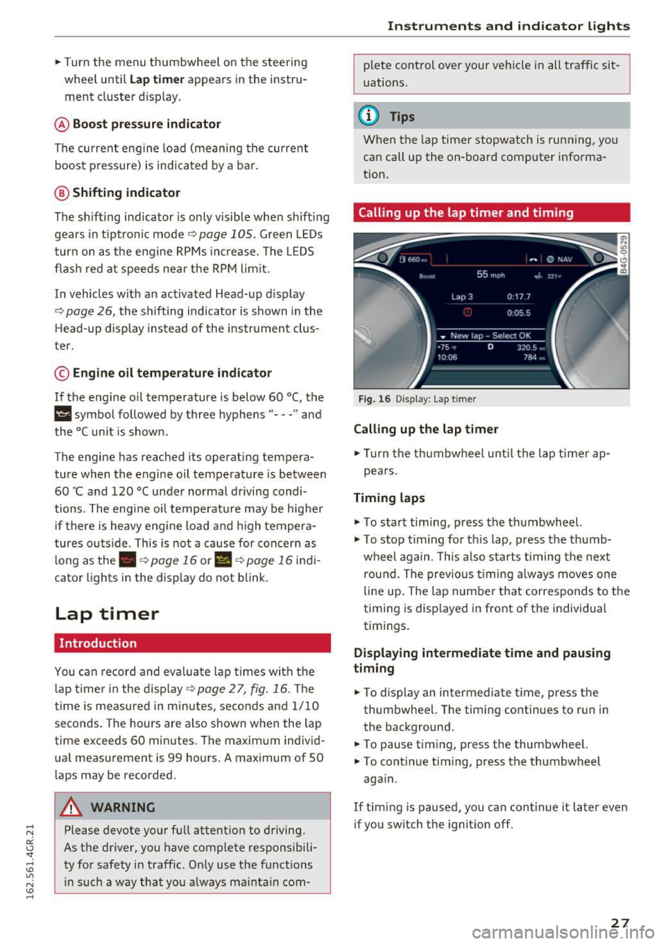
Lap timer
Introduction
You can record and evaluate lap times with the
lap timer in the display <=>
page 2 7, fig. 16. The
time is measured in minutes, seconds and 1/10
seconds. The hours are also shown when the lap
time exceeds 60 minutes. The maxim um individ
ua l measurement is 99 hours. A maximum of SO
laps may be recorded.
A WARNING
Please devote your full attention to driving.
As the driver, you have complete responsibili
ty for safety in traffic. Only use the functions
in such a way that you always maintain com-
-
Instruments and indicator lights
plete control over your vehicle in all traffic sit
uations.
(D Tips
When the lap timer stopwatch is running, you
can call up the on-board computer informa
tion.
Calling up the lap timer and timing
Fig. 16 Display : Lap timer
Calling up the lap timer
.. Tu rn the thumbwheel unti l the lap timer ap-
pears.
Timing laps
.,. To start tim ing, press the thumbwheel.
.,. To stop tim ing for this lap, press the thumb
wheel again . T his also starts timing the next
round. The previous timing always moves one
line up. The lap number that corresponds to the
timing is displayed in front of the individua l
timings.
Displaying intermediate time and pausing
timing
.. To display an intermediate time, press the
thumbwheel. The timing continues to run in
the background.
.. To pause timing, press the thumbwheel.
.. To continue timing, press the thumbwheel
aga in .
If timing is paused, you can continue it later even
if you switch the ignition off.
27
Page 184 of 282
Intelligent Technology
- Driving in deep snow or on loose ground
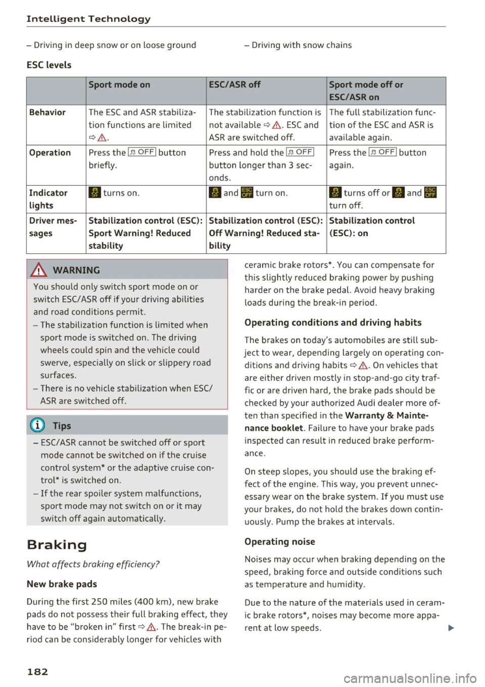
ESC levels
- Driv ing with snow chains
Sport mode on ESC/ASR off Sport mode off or
ESC/ASRon
Beha vior
The ESC and ASR stabiliza- The stabiliza tion function is The f ull stabilization tune-
tion f unctions are limited not available ¢
,&. ESC and
tion of the ESC and ASR is
¢
&. . ASR are switched off . avai
lab le aga in .
Op eration Press the I B OFF I button Press and hold the !B OFFI Press the IB OFFI button
briefly . button longer than 3 sec- again.
onds.
I n d ica to r II turns on. II and lit turn on. II turns off or II and II
light s turn off .
Driver me s- Stabili zation cont rol (E SC): S tabilization control (E SC ):
Stabili zation cont rol
s age s Sport Warning ! Redu ced Off Wa
rning! Reduced sta - (ESC ): on
st abilit y
A WARNING
You should only switch sport mode on or
switch ESC/ ASR off if your driving abilities
and road conditions permit.
bility
- The stabilization function is limited when
sport mode is sw itched on. The driving
wheels co uld spin and the vehicle could
swerve , espec ially on s lick o r slippery road
s u rfaces.
- The re is no vehicle stab ilizat ion when ESC/
ASR a re swi tched off .
(D Tips
-ESC/ASR cannot be switched off or sport
mode cannot be switched on if the cru ise
control system* or the adaptive cruise con
tro l* is switched on .
- If the rear spoiler system malfunct ions,
sport mode may not switch on or it may switch off ag ain automatically .
Braking
What affects braking efficiency?
New brake pads
During the first 250 miles (400 km), new brake
pads do not possess the ir full braking effect, they
have to be "broken in" first¢&, . The b reak-in pe
riod can be considerably longe r fo r vehicles with
182
ceramic brake rotors* . You can compensate for
this slightly reduced braking power by pushing harder on the brake pedal. Avoid heavy braking
l oads during the break-in per iod.
Op erating c ondition s and dri ving habits
The brak es on today 's automobiles are still sub
ject to wear, depending large ly on operating con
dit ions and driving habits ¢&, . On vehicles that
are either driven mostly in stop-and-go city traf
fic or are driven hard, the brake pads shou ld be
checked by your authorized Audi dealer more of
ten than specified in the
Warr ant y & Maint e
nance booklet .
Failure to have your brake pads
i nspected ca n result in red uced b rake perfo rm
ance.
On steep slopes, you should use the brak ing ef
fect of the engine . Th is way, you prevent unnec
essa ry wea r on the brake system. If you must use
you r brakes, do not ho ld the brakes down contin
u ous ly. P ump the brakes at intervals.
Operating noi se
Noises may occur when brak ing depending on the
speed, braking force and outside conditions such as temperature and h umid ity.
Due to the nature of the mater ials used in ceram
i c brake rotors*, no ises may become more appa-
rent at low speeds. ..,.
Page 188 of 282
Intelligent Technology
Audi dealer immediately to have the malfunction
corrected. The color of the indicator light depends on the vehicle speed.
_& WARNING
-
Driving at higher speeds without the rear
spoiler deployed can impair handling charac
teristics, making the vehicle harder to con
trol.
- Always make sure that the spoiler is de
ployed when driving at speeds over 85 mph
(140 km/h) . If the rear spoiler warning/indi
cator light in the instrument cluster comes
on, the rear spoiler may not have deployed.
- Never drive at speeds higher than 85 mph
(140 km/h) if the spoiler is not deployed .
Have the spoiler inspected as soon as possi
ble by an authorized Audi dealer or qualified
workshop.
- Always obey speed limits and other traffic
laws.
_& WARNING
Improper operation of the rear spoiler can
cause crushing injuries.
- Always make sure that nobody, especially
children, is in the way when the rear spoiler
is deployed or retracted.
@) Note
- Never push on the vehicle on the rear spoil
er . This could cause damage.
- To prevent damage to the rear spoiler do
not lean or place anything on it.
-
- Only operate the rear spoiler manually when
the luggage compartment lid is close and
the rear spoiler moving parts are not
blocked. Otherwise, damage could occur.
(D Tips
Clean the rear spoiler compartment every 2 to
3 months. To function correctly, the rear
spoiler must be free of ice, snow and leaves.
186
Energy management
' The starting ability is optimized
The energy management system manages the
electrical energy distribution and optimizes the
availability of electrical energy for starting the
engine.
When a vehicle with a conventional energy sys
tem is not driven for a long time, the battery is
drained by equipment (for example the immobil
izer). In certain circumstances , there could may
not be enough energy to start the engine .
Your vehicle is equipped with an intelligent ener
gy management system for distributing electrici
ty. This significantly improves the starting ability
and increases the battery life.
The energy management system Is made up of
battery diagnosis , idling current management
and dynamic energy management.
Battery diagnosis
The battery diagnosis determines the battery charge level. The sensors detect the battery, the
battery current, and the battery temperature .
The current charge level and the performance of
the battery are determined based on this.
Idling current management
The idling current management decreases the
energy used while parked . With the engine
switched off, it manages the energy distribution
to the different electrical components. Date from
battery diagnosis is taken into account for this.
Depending on the battery charge level, electrical
equipment is switched off one item after the oth
er, to prevent the battery from draining and to
retain the starting ability.
Dynamic energy management
While driving, dynamic energy management dis
tributes the appropriate amount of energy to the
electrical equipment .
It controls the battery
charge level so that more energy is not used then
is being generated in order to maintain an opti-
mal battery charge level.
ll>
Page 191 of 282
CD Note
-Vehicle components such as the engine,
transm ission, suspension or electrical sys
tem can be severely damaged by driving
through water.
- Determine the depth before driv ing through
water.
- Do not stop the vehicle, drive in reverse or
switch the eng ine off when dr iving through
water.
- Keep in mind that oncoming veh icles may
create waves that raise the water level and
make it too deep for your vehicle to drive
through safely .
- Avo id d riving through salt water (corrosion).
Warming up and cooling
down
By carefully warm ing up and cool ing down your
veh icle, you can he lp ensure that it is not over
stressed un necessa rily during sporty driving.
When warming up, the vehicle is dr iven at a max
i mum eng ine speed of 6000 RPM in order to raise
the eng ine oi l temperature to a min imum of
140 °F (60 °C). The tires a lso on ly reac h their f ull
road ho ld ing capability once they have warmed
up .
The cooling fan can continue to run in your vehi cle after the engine is swi tched off. Howeve r,
d riving the vehicle to cool it dow n is particularly
important. D uring sporty dr iv ing, the engine and
brakes, the exhaust system, and the transmission
a ll become extremely hot. Before you park the
ve hicle, you shou ld drive it for a few m iles/kilo
meters at light load in the low rpm range to al
low it to cool down.
Driving and the envir onment
Catalytic converter
Applies to: veh icles w ith gasoli ne e ngi ne
It is very important that your emission control
system (catalytic converter) is functioning prop
erly to ensure that your vehicle is running in an
environmentally sound manner .
.. Always use lead-free gasoline¢ page 198,
Fuel supply.
.. Never run the tank down all the way to empty.
.. Never put too much motor o il in yo ur engine
¢ page 20 7, Adding engine oil 9:::r. .
.,. Never try to pus h- or tow-start your veh icle.
The catalytic co nverter is an efficient "clean-up"
device built into the exhaust sys tem of t he ve hi
cle. The catalyt ic conv erter b urns ma ny of the
po llutants in the exhaust gas before they are re
leased into the atmosphere.
The exclusive use of un leaded fuel is cr itically im
po rtant fo r the life of the catalytic converte r and
prope r fu nct io ni ng of the eng ine.
_&. WARNING
The tempe ra tu re o f th e exh aus t sys tem is
hi gh, bot h when driv ing and a fter stopping
the engine.
- Never tou ch the e xhaus t tail pipes on ce they
have become hot. This cou ld res ult in burns.
- Do not p ark or operate the vehicle in ar eas
where the hot exhaus t sys tem may come in
contact w ith dry grass, b rush, fuel spill or
other mate rial which can ca use a fire.
- Do not app ly additiona l undercoating or
r u stp roofing on or near the exhaust mani
fold, exha ust pipes, cata lytic converter or
heat shields. D uring driving, the substance
used for undercoat ing could overheat and
cause a fire.
CD Note
- Be aware that just one tank fi lling with
leaded fuel w ill already seriously degrade
the performance of the catalytic converter.
- Do not exceed the correct engine oil leve l
¢page 207.
189
Page 211 of 282
Cooling system
Coolant
The engine coolant performs two functions: it
keeps the engine from overheating and it pro
tects the engine from freezing in the winter .
The cooling system is sealed and generally re
q ui res little atte ntion .
The cooling system has been filled at the factory
with a permanent coolant which does not need to
be changed . The coolant consists of a mixture of
specially condit ioned water and the ma nufactur
er's glycol-based coolant additive G13 an tifreeze
with ant icor rosion additives
(50% for USA mod
e ls;
60% fo r Canadia n models). This m ix tu re
bo th ass ures the necessa ry fros t prote ction and
protects metal componen ts in the engi ne's coo l
ing system from corrosion and scaling .
It also
raises the boiling point of the coolant.
D o not red uce the con cen trat ion of the coolant in
the summer by adding p lain wa ter.
The propor
tion of coolant additive mu st be at least 50 %
but not more than 60%
to maintain antifreeze
protection and cooling efficiency. If the coolant
frost protection is too low, the coolant could
freeze and damage the vehicle heating and en
g ine cooling system .
For year-round driving, antifreeze is added at the
factory for temperatures down to:
- -3 1 °F ( -3 5 °C) USA
- -4 0 °F ( - 40 °C) Canada.
If yo u m ust add coo lant, use a m ixt ure of water
and coolant addit ive. Mixing the cool ant additive
with d istilled w ater is recommended .
_& WARNING
Before you che ck anythi ng in t he eng ine com
pa rtment, a lways read and heed a ll WARN
INGS
~ .& in Working in the engine compart
ment on page 203 .
(D Note
-Before winter se ts in, have the coo lant
checked to see if the coolant additive in your
vehicle is sufficient to meet the c limate con -
Checking and Filling
ditions. This is especia lly important if you
live in a region whe re the winter is extreme
ly cold. If necessary, increase the propo rtion
of coolant addit ive to
60%.
- Whe n adding coolant additive to your cool
ing system, remember :
- We recommend us ing o nly coola nt addi
tive G 12++ or G13 (c hec k the label) for
y o ur vehi cle. Thi s coo lant ad ditive is av ail
abl e at a uth orized Au di dea le rs. Ot her
types o f ant ifreeze ca n sign ifican tly re
d uce corrosion protection. The resu lting
cor ros ion can cause a loss of coolant and
se rious engine damage.
- Do not add any type of radiator leak sealant
to your vehicle's engine coolant . Adding ra
diator repair fluid may adversely affect the
function and performance of your cooling system and could result in damage not cov
ered by your New Veh icle Limited War ra nty .
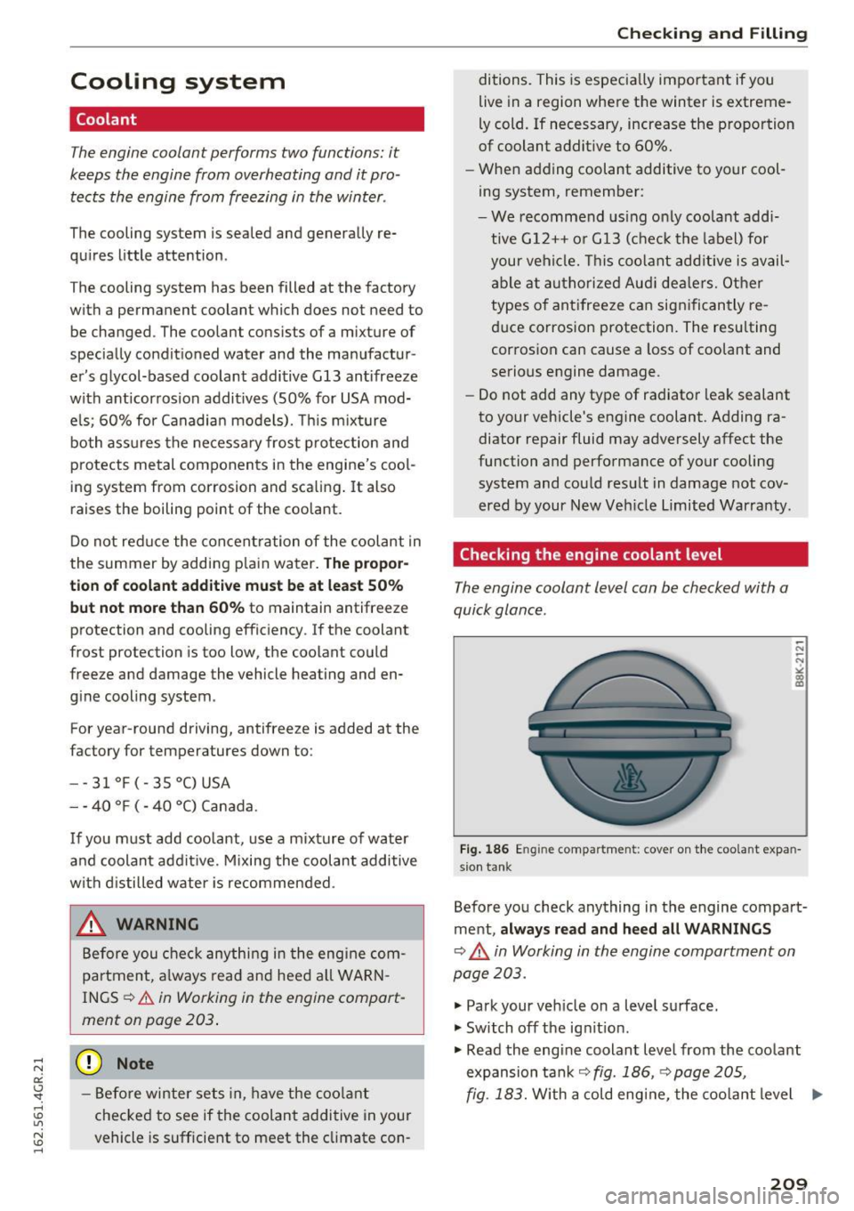
Checking the engine coolant level
The engine coolant level can be checked with a
quick glance .
Fig. 186 E ngine compar tmen t: cover on t he coo lant expan
s io n t ank
Befo re you check anything in the engine compart
me nt,
always read and heed all WARNINGS
~ .&. in Working in the engine compartment on
page 203.
" Park your veh icle on a leve l s u rface.
" Sw itch off the ig nit ion .
.. Read the eng ine coolant leve l from the coo lant
expansion tan k
r=;,fig. 186, r=;,page 205,
fig . 183.
W ith a cold eng ine, the coolant level ..,.
209
Page 214 of 282
Checking and Filling
"' Read the brake fluid level from the brake fluid
reservoir
¢ fig. 187, ¢page 205, fig. 183. The
brake fluid level must be between the "MIN"
and "MAX" markings.
The location of the brake fluid reservoir can be
seen in the engine compartment illustration
c>page205.
The fluid level may drop slightly after some time
due to the automatic adjustment of the brake
pads. This is not cause for alarm.
If the brake fluid level falls considerably below
the "MIN" mark, the brake warning/indicator
light
1111 (U.S. models)/ . (Canadian models)
will come on¢
page 14. Do not continue to oper
ate the vehicle. The complete brake system
should be thoroughly checked by an authorized
Audi dealer or other qualified facility and the
cause corrected . If the brake fluid level is too
low, the brake warning/indicator light will illumi
nate. Contact an authorized Audi dealer
immedi
ately.
Changing brake fluid
Have the brake fluid changed by an experienced
technician.
Brake fluid absorbs moisture from the air . If the
water content in the brake fluid is too high , cor
rosion in the brake system may result after a pe
riod of time. The boiling point of the brake fluid
will also decrease considerably and decrease
braking performance.
Therefore, the brake fluid must be changed
every
two years.
Always use new brake fluid which con
forms to Federal Motor Vehicle Standard "FMVSS
116 DOT 4".
The brake fluid reservoir can be difficult to reach,
therefore, we recommend that you have the
brake fluid changed by your authorized
Audi
dealer.
Your dealer has the correct tools, the
right brake fluid and the know-how to do this for
you.
212
A WARNING
-
- Brake fluid is poisonous. It must be stored
only in the closed original container out of
the reach of children!
- Brake failure can result from old or inappro
priate brake fluid. Observe these precau
tions:
- Use only brake fluid that meets SAE speci
fication
J 1703 and conforms to Federal
Motor Vehicle Standard 116. Always check
with your authorized Audi dealer to make
sure you are using the correct brake fluid.
The correct type of brake fluid is also indi
cated on the brake fluid reservoir .
- The brake fluid must be new. Heavy use of
the brakes can cause a vapor lock if the
brake fluid is left in the system too long .
This can seriously affect the efficiency of
the brakes as well as your safety. This
could result in an accident.
(D Note
Brake fluid will damage the paint of your vehi
cle.
@ For the sake of the environment
Because of the problem of proper disposal of
brake fluid as well as the special tools re
quired and the necessary expertise, we rec
ommend that you have the brake fluid
changed by your authorized Audi dealer .
Battery
General information
Under normal operating conditions, the battery
in your Audi does not need any maintenance.
With
high outside temperatures or long daily
drives we recommend that you have the electro
lyte level checked by a service facility. The elec
trolyte level should also be checked each time
the battery is charged ¢
page 214.
Have the battery checked when you take your ve
hicle in for service. You are well advised to re
place a battery that is older than S years.