ECU AUDI S3 2009 Service Manual
[x] Cancel search | Manufacturer: AUDI, Model Year: 2009, Model line: S3, Model: AUDI S3 2009Pages: 324, PDF Size: 76.02 MB
Page 273 of 324
What do I do now? -
------------------
& WARNING !continued)
• Always make sure the spare tire and even a flat tire are secured
in place and not loose, otherwise they could fly forward, causing
personal injury to passengers in the vehicle in an accident or
sudden maneuver .
• Never use the jack supplied with your Audi on another vehicle,
particularly on a heavier one. The jack is only suitable for use on
the vehicle it came with. •
Ap plies to vehicles: w ith compact spare wheel
Compact spare wheel
The compact spare wheel is only intended to be used for
a short Nme.
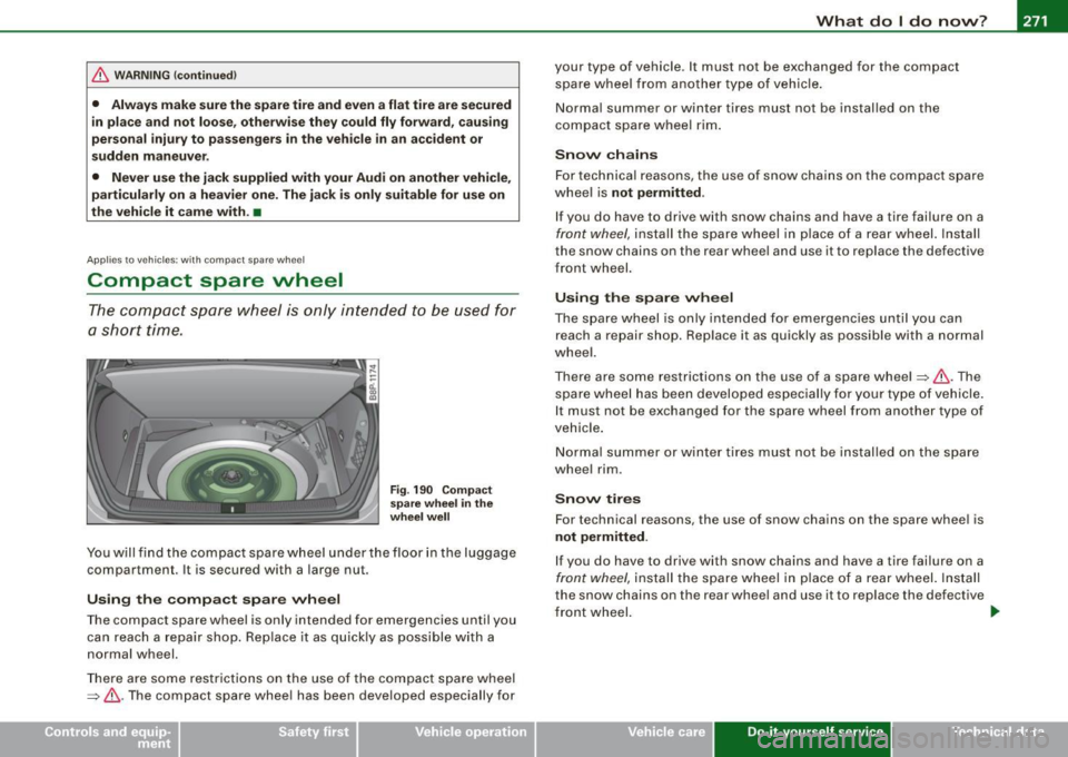
Fig . 190 Compact
spare wheel in the
wheel well
You will find the compact spare wheel under the floor in the luggage
compartment. It is secured with a large nut.
Using the compact spare wheel
The compact spare wheel is only intended for emergencies until you
can reach a repair shop. Replace it as quickly as possible with a
normal wheel.
There are some restrictions on the use of the compact spare wheel
=>
& -The compact spare wheel has been developed especially for your type of vehicle
. It must not be exchanged for the compact
spare wheel from another type of vehicle.
Normal summer or winter tires must not be installed on the
compact spare wheel rim.
Snow chains
For technical reasons, the use of snow chains on the compact spare
wheel is
not permitted .
If you do have to drive with snow chains and have a tire failure on a
front wheel, install the spare wheel in place of a rear wheel. Install
the snow chains on the rear wheel and use it to replace the defective
front wheel.
Using the spare wheel
The spare wheel is only intended for emergencies until you can
reach a repair shop. Replace it as quickly as possible with a normal
wheel.
There are some restrictions on the use of a spare wheel =>& .The
spare wheel has been developed especially for your type of vehicle.
I t must not be exchanged for the spare wheel from another type of
vehicle.
Normal summer or winter tires must not be installed on the spare
wheel rim .
Snow tires
For technical reasons , the use of snow chains on the spare wheel is
not permitted .
If you do have to drive with snow chains and have a tire failure on a
front wheel, install the spare wheel in place of a rear wheel. Install
the snow chains on the rear wheel and use it to replace the defective
front wheel.
t,.
Vehicle care Do-it-yourself service irechnical data
Page 274 of 324
-L___:W:..:..:. h.:.: a::.. t:...:: d:.:o:::....:. l..: d::. O ::::....: n:..:.:: O:..:W :.:..:. ? ____________________________________________ _
& WARNING
Always store jacking equipment, spare wheel in the luggage
compartment. Tighten screw for the spare wheel securely. Under
no circumstances should you store the spare wheel or jack and
tools unsecured in the passenger compartment. This could cause
serious personal injury to passengers in the vehicle in case of a
collision.
• The compact spare tire is for temporary use only and is so
marked on the sidewalls.
• Do not drive at speeds exceeding 50 mph (80 km/hi with the
compact spare wheel mounted. Also rapid acceleration, hard
braking and hard cornering must be avoided to help prevent loss
of vehicle control.
• Any continuous road use of the compact spare tire may result
in tire failure, loss of vehicle control and injury to vehicle occu
pants.
• Do not put a snow chain on your compact spare tire. Due to the
smaller tire size, the chain will not fit properly and can thus
damage your vehicle. You could also lose the chain, as well as
control of the vehicle .
• If you have a flat front tire in road conditions which require
snow chains, first remove the undamaged rear wheel and mount
the compact spare wheel in its place. Then remove the damaged
front wheel, take the snow chains off it and attach them to the
wheel taken from the rear. This wheel can now be mounted on the
front with its snow chains. Check and adjust tire pressure promptly.
• Never use two or more compact spare tires at the same time.
0 Note
When using the compact spare wheel, note the following: •
After installing the compact spare wheel, the tire inflation pres
sure should be checked and, if necessary, increased to 60 psi (4 .2
barl.
• The load carrying capacity is marked on the tire sidewal ls and
must not be exceeded .
• After installing the compact spare wheel, make sure that you
remount the flat tire in its storage area properly .
• The compact spare tire should be properly remounted in its
storage area as soon as the standard road tire can be replaced.
• Because the compact spare tire was specifically designed for
your vehicle, it must not be used on any other vehicle . Likewise,
compact spare wheels from other vehic les must not be used on your
vehicle.
• The compact spare tire must not be mounted on any other
wheels, nor must standard tires, snow tires, wheel covers or trim
rings be used with the compact spare wheel. If such use is
attempted, damage to these items or other vehicle components
may occur.
[ i] Tips
Check the inflation pressure of the compact spare tire (60 psi/4 .2
bar) periodically to keep the tire ready for use .•
Wheel change
Before changing a wheel
Observe the following precautions for your own and your
passenger's safety when changing a wheel.
- After you experience a tire failure, pull the car well away
from moving traffic and try to reach level ground before
you stop
~ & . ~
Page 275 of 324
What do I do now? -__________________ __;__:....:....:..:: __ _
•
-All passengers should leave the car and move to a safe
location (for instance, behind the guardrail)~& .
- Apply the
parking brake firmly ~& .
- Move
selector lever to position Pon an automatic trans-
miss ion; put manual transmission in
first gear ~& .
-If you are towing a trailer : unhitch the trailer from your
vehicle.
- Take the
tool and the spare tire~ page 270 out of the
luggage compartment.
& WARNING
You or your passengers could be injured while changing a wheel if
you do not follow these safety precautions:
• If you have a flat tire, move a safe distance off the road. Turn off
the engine, turn the emergency flasher on and use other warning
devices to alert other motorists.
• Make sure that passengers wait
in a safe place away from the
vehicle and well away from the roadway and traffic.
• To help prevent the vehicle from moving suddenly and possibly
slipping off the jack, always fully set the parking brake and block
the wheel diagonally opposite the wheel being changed. When one
front wheel is lifted off the ground, placing the automatic trans
mission in "P" (Park), or engaging a gear in a manual transmission
will
not prevent the vehicle from moving.
• Before you change a wheel, be sure the ground is level and firm.
If necessary, use a sturdy board under the jack.
• After installing the spare wheel, make sure that you remount
the flat tire/wheel in its storage area properly and tighten the
knurled retaining screw securely. •
Changing a wheel
When you change a wheel, follow the sequence described
below step-by-step and exactly in that order.
1. Remove the decorative wheel cover*. For more details
see also
~ page 274, "Decorative wheel covers" or
~ page 275, "Wheels with cap-covered wheel bolts".
2. Loosen the
wheel bolts ~ page 276.
3. Locate the proper mounting point for the jack and align the jack below that point~
page 276.
4. Lift the car with the jack~ page 276.
5. Take the flat wheel off and then put the spare on
~ page 278.
6. Tighten all wheel bolts lightly .
7.
Lower the vehicle with the jack .
8. Use the wheel bolt wrench and
firmly tighten all wheel
bolts
~ page 276.
9. Put the decorative wheel cover* back on.
& WARNING
Always read and head all WARNINGS and information ::} & in
"Raising the vehicle" on
page 276 and ~ page 279. •
After changing a wheel
A wheel change is not complete without the following
actions.
- Store and secure the replaced wheel in the spare wheel
well. .,._
Do-it-yourself service
Page 279 of 324
_____________________________________________ W_ h_ a_t _d_ o_l _ d_o _ n_o_ w_ ? _ __._
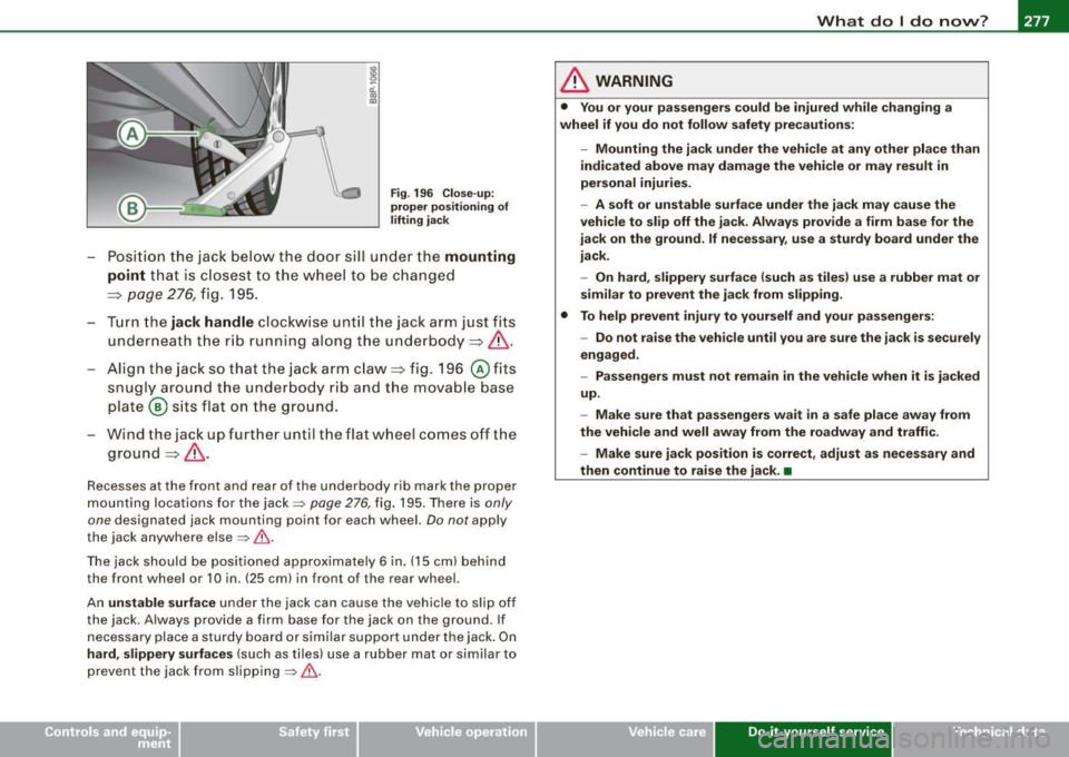
Fig. 196 Close- up:
prope r po sit io ning of
lifting ja c k
- Posi tion the jack bel ow the doo r sill u nder t he mounting
point
t ha t is clos est to the w hee l to be ch an ged
==> page 2 76, fi g. 19 5.
- Tur n the
jack handle cl ockwise un til the ja ck arm jus t fit s
un derne ath th e r ib runni ng a lo ng the und erbo dy ==:> & .
- Align t he jack so tha t the ja ck a rm claw ==:> fig. 196
© fits
snugl y aro un d t he un derb od y r ib an d t he mov ab le base
p lat e@ sit s fla t on t he grou nd.
- Win d the jac k up furt her until t he flat wheel comes off the
groun d==:> & .
Recesses a t the front and rear of the underbody rib mark the proper
m ounti ng lo ca tions for the jack=>
page 276, fig . 195. There i s only
one
designated jac k mounting po int for each wheel. Do not app ly
the jack anywhe re e lse
=> & .
The jac k sh o uld be pos it ioned appro ximat ely 6 in. (15 cm) b ehind
the front wheel or 10 in. (25 cm) in front o f the rear whee l.
An unstable surface und er the jack can cause the veh icle to s li p o ff
the jack. A lways provide a firm base for the jack on the ground . If
n ece ssary place a s turd y b oa rd or sim ila r su p po rt und er the jack . On
hard , slippery surfaces (such as t ile s) use a rubber mat or s imilar to
pr even t the jack fr om slip ping =>& .
& WARNING
• You or your passengers could be injured wh ile changing a
wheel if you do not follow safety precautions:
-Mounting the jack under the vehicle at any other place than
indicated above may damage the vehicle or may result in
per sonal injuries.
- A soft or unstable surface under the jack may cause the
vehicle to slip off the jack . Always provide a firm base for the
j ack on the ground. If necessary , use a sturdy board under the
jack.
- On hard, slippery surface (such as tiles ) use a rubber mat or
similar to prevent the jack from slipping .
• To help prevent injury to yourself and your passengers:
-Do not raise the vehicle until you are sure the jack is securely
engaged.
- Passengers must not remain in the vehicle when it is jacked
up.
- Make sure that passengers wait
in a safe place away from
the vehicle and well away from the roadway and traffic .
- Make sure jack position is correct, adjust as necessary and
then continue to rai se the jack. •
Vehicle care Do-it-yourself service Technical data
Page 281 of 324

_______________________________________________ W_ h_ a_t _ d_ o_ l _d _o_ n_ o _ w_ ? __ ffllll
•
• T he wheel bolts should be clean and easy to turn . Check for dirt
and corrosion on the mating surfaces of bo th the wheel and the
hub. Remove all dirt from these surfaces before remounting the
whee l.•
Tires with unidirectional tread design
Tires with unidirectional tread design must be mounted
with their tread pattern pointed in the right direction.
Using a spar e tir e with a tread pa ttern intended for u se
in a sp ecific direc tion
When using a spare tire with a tread pattern intended for use in a
specific direction , p lease note the following:
• T he direction of rotation is marked by an arrow on the sid e of the
tire .
• I f the spare tire has to be installed in the incorrec t direction in the
event of a flat tire , use the spare tire on ly temporarily since the tire
wi ll not be ab le to achieve its optimum performance characteristics
with regard to aquap laning, noise and wear .
• We recommend that particula r atten tion be pa id to this fact
dur ing wet weather and that you adjust your speed to match road
conditions.
• Replace the flat tire with a new one and have it installed on your
vehicle as soon as possible to restore the handling advantages of a p roper ly pointed d irection -dependent t ire. •
Notes on wheel change
Please read the information=> page 255, "New tires and replacing
tires and wheels" if you are going to use a spare tire which is
different from the tires on your veh ic le.
Aft er you change a tire :
• Che ck the ti re pre ss ure on the spare immed iately aft er
mounting .
• Have the wheel b olt t ight en ing to rque checked with a torque
wrench a s soon a s po ssible by your authorized Audi dea ler or a
q u alified service stat ion .
• On steel and a lloy wheel rims , the wheel bolt s are correctly tight
ened with a t orque of 90 ft lb (1 2 0 Nm l.
• If you noti ce w hile changing a tire that the wheel bolt s are
c o rroded and d iff ic ult to turn , then they should be repla ced befo re
you check the tightening torque.
• Repl ace the fl at t ir e w ith a new one and hav e it installed o n your
vehicle as soon as pos sib le . Remount the wheel cover .
Until then , drive wi th ext ra care and at redu ced speeds.
& WARNING
• If you are going to equip your v ehi cle wi th tire s or rim s wh ich
diffe r from tho se which were fa ctory installed , th en be sure to r ead
the infor mation
=> page 255, " New tires and repl acing tire s and
wheel s".
• Alway s ma ke sure the d amag ed w heel or e ven a flat t ire and
the jack and tool kit ar e properly secured in the lugg age comp art
ment and are not loose in the p asse nger co m partment .
• In an a ccident o r sudden maneu ver th ey could fl y fo rw ard ,
injur ing anyo ne in th e vehi cle .
• Alway s store damaged wheel , ja ck and tool s se curel y in
luggag e compartment . Oth erwi se, in an accid ent or sudd en
m aneuv er the y could fly fo rward, c au sing in jur y to pa ssenge rs in
the vehic le . •
Do-it-yourself service
Page 290 of 324

11111.___E_ m _ e _r-==g :...e_ n_ c...:y _ s_ i_t _u _a _t_ i_o _n_ s _______________________________________________ _
& WARN ING (continued )
• Before you check anything in the engine compartment , always
read and heed all WARNINGS=>
page 217, "Engine compa rt m ent" .
0 Note
• Applying a higher voltage booster battery wil l cause expensive
damage to sensitive electronic components, such as contro l units,
relays, rad io, etc.
• There must be no electrical contact between the vehicles as
otherwise current cou ld already star t to flow as soon as th e positive
(+ ) termina ls are connected .
• Improperly connected jumper cab les can cause substantia l
damage to the electrica l system of the vehic le.
[ i ] Tips
• The disc harged battery must be p ro per ly connected to the
ve hicle's elec trica l syste m.•
General information of starting
assistance
Please observe that the p rocedure described below for conn ect in g
jumper cab les is intended to provide a jump start for your vehicle.
M ake s ure th at th e connec ted cla mps have su ffic ien t
me tal contact .
Start assistance differs for vehicles with a 4-cylinder engine and a 6-
cy lind er eng ine:
=> page 289, "Use of jumper cables (4 cyl inder eng ine)"
=> page 290, "Use of jumper cables (6 cylinder engine)"
& WARNING
Improper handling of the jumper cables can lead to an explosion
of the battery and severe injuries. To reduce the risk of injury , note
the following :
• The sections of the terminal clamps that are not insulated
must not tou ch ea ch other . In addition , the cable clamped to the
battery 's positive terminal must not come in contact with electri
cally conne cted parts of the vehicle -danger of short cir cuit!
• Route the jumper cable so that it cannot cat ch in any rotating
parts in the engine compartment .
• Do not bend over the batteries -danger of chemical burns!
• The battery cell locking screws must be tightened securely .
• Keep ignition sources (open flame, burning cigarettes, etc .)
away from the batteries -danger of explosion!
• Do not clamp the minus cable to parts of the fuel system or the
brake lines.
0 Note
If you prov id e s ta rt assi sta nce f or others w ith your veh icle, yo u
should not c lamp the mi nus cab le (-) to the negative termina l of the
discharged battery=>
page 289 , fig . 203 © but to a solid metal pa rt
screwed firmly to t he engi ne b lock, or to the engin e block itsel f. In
case of an inadequately vent ilated battery of the vehicle receiving
p owe r, the re is a danger o f expl osio n due to deton ati ng gas! •
Page 292 of 324
IIII.___E_ m_ e_r -=g "-e_ n _ c-=y _ s_ i_t _u _a _t_ i_o _n_ s _______________________________________________ _
13. Disconnect the c able while the engine is r unning exactly
in
reverse order to that described in~ page 289,
"Connecting/d isconnecting the jumper ca ble .". When
doing so, make sure t hat the cable cannot contact
rotating engine parts.
14 . Tur n the heater blower and t he rea r window heating off
again .
The battery is vented to the outside to prevent gases from entering
the vehicle interior.
Make sure that the jumper clamps are well connected with their
metal par ts in full contac t with the battery terminals.
& WARNING
To avoid seri ous pe rson al injur y and d am age to the vehi cle , heed
all warning s and in struct ion s of the jumper cable m anufa ctur er. If
in doubt , call for ro ad se rvic e.
• Jumper cable s mu st be l ong enough so that the vehicle s do not
t ou ch .
• When connecting jumper cable s, make sure that th ey cannot
g et ca ught in any mov ing p arts in the e ngine compa rt m ent .
• Bef ore you che ck anything in the engine com partment , al way s
r ea d and h eed all WARNINGS ~
page 217, "Engine compar tment".
0 Note
Improperly connected jumper cables can damage or destroy the
generator.
• Always conn ect POSITIVE ( +l to POSITIVE( +), and NEGATIVE( -) to
NEGAT IVE( -) terminal.
• Check that all screw plugs on the battery cel ls are screwed in
firm ly. If no t, tigh ten plugs prior to connecting clamp on negative
battery term inal. •
Please no te that the procedure for connecting a jumper cable as
described above applies specifical ly to the case of your vehicle
being jump started. When you are giving a jump start to another
veh ic le , do
not connect the minus(-) cab le to the minus( -) terminal
on the discharged battery ©~
page 289 , fig. 203 . Instead, securely
connect the minus( -) cab le to either a massive metal component
that is firmly bolted to the engine block or to the engine block itself .
I f the battery that is being charged does not vent to the outside,
escap ing battery gas cou ld ignite and explode !•
Use of jumper cables (6 cylinder
engine)
Make sure to connect the jumper cable clamps in exactly
the order described below!
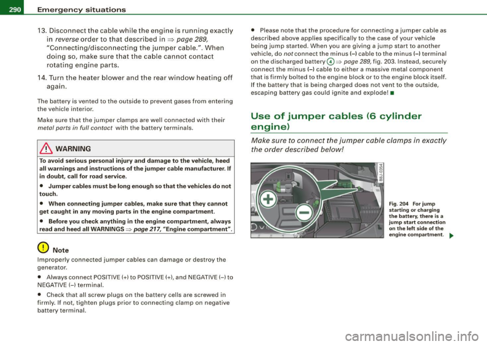
Fi g. 2 04 For jump
starti ng or charging
th e batt ery, th ere is a
j ump start co nnect io n
o n th e le ft side o f the
en gine com partment. .,_
Page 294 of 324
-L~E=m~e::,r~g~e~n~c::.y!'....:s~i:,.::t~u=.,::a:=.:t:!i.:::o:.:.n.:.:s~ ---------------------------------------------
15. Turn the hea ter blowe r and th e rear wind ow heat er off
aga in.
The battery is ve nted to the outs ide to preve nt gases from e nter ing
the veh icle interior.
M ake sure tha t th e jum per c lamps are well co nnected w ith their
metal parts in full contact with the battery terminals .
& WARNING
To avoid serious personal injury and damage to the vehicle , heed
all warnings and instructions of the jumper cable manufacturer. If
in doubt , call for road service .
• Jumper cables must be long enough so that the vehicles do not
tou ch .
• When connecting jumper cables , make sure that they cannot
get caught in any moving parts in the engine compa rtment .
• Before you check anything in the engine compartment , always
read and heed all WARNINGS=>
page 217, "Engine compartment ".
0 Note
Improperly connected jumper cab les can damage or destroy the
ge nerator.
• Always connec t POSI TIVE (+) to P OSITIV E(+), and NEGATIVE (-l to
N EGA TIVE( -) te rmi nal.
• Chec k th at a ll screw plugs o n the ba ttery cel ls are screwe d in
fi rm ly. If not, t ighten plu gs prio r to connect ing cla mp on neg ative
batte ry te rmina l.
• Please note that the procedure for connecting a jumper cab le as
de scribed abo ve applies specifical ly to the case of y our vehicle
being ju mp s tarted. W hen you ar e giving a jump start to anoth er
vehic le, do
not connect the mi nus( -) ca ble to the m inus( -) te rmina l
on the disc ha rged battery ©=>
page 28 9, fi g. 203. Ins tead, secu re ly
connect the minus( -) cable to either a massive metal component that is firm
ly bolted to the engine b lock or to the engine block itself.
I f t he b att ery t hat is bei ng c harge d does not vent t o th e ou ts id e,
escap ing battery gas cou ld ignite and explode !
[ i ] Tips
In the Aud i A3 with the 6 -cy linder engine, the battery is located
b el ow the luggage c ompartmen t fl oor, pro tec ted by a me ta l sh rou d.
Access requ ires pro fess io na l skill and special tools. •
Emergency towing with commercial
tow truck
General hints
You r Audi req uir es s pec ial ha ndl ing fo r t owin g.
T he fo llo wi ng infor matio n is to b e used by com merc ial tow t ru ck
operators who know how to operate the ir equ ipment safe ly.
• Never tow your Audi , towing will cause damage to the engine
and transmission .
• Never wrap the safety chains or winch cables around the brake
lines .
• To prevent unnecessary damage, your Audi must be transported
with a car carrier (flat bed truck) .
• To load the vehicle on to the flat bed , use the towing loop found
in the vehicle tools and attach to the front or rear anchorage
=> p ag e 293 and => page 293.
& WARNING
A vehicle being towed is not safe for passengers. Never allow
anyone to ride in a vehicle being towed , for any reason . •
Page 295 of 324
________________________________________________ E_ m_ e_r ,,::g c..e_ n _ c..::y;._ s_ i_t _u _a_ t_ i_o _n_ s _ ___.fflll
Front towing loop
Do not install the front towing loop until it is needed.
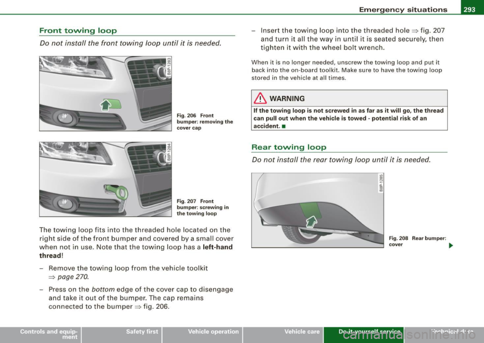
Fig. 206 Front
bumper: removing the
cover cap
Fig . 207 Front
bumper: screwing in
the towing loop
The towing loop fits into the threaded hole located on the
right side of the front bumper and covered by a small cover
when not in use. Note that the towing loop has a
left-hand
thread!
- Remove the towing loop from the vehicle toolkit
=>
page 270.
- Press on the bottom edge of the cover cap to disengage
and take it out of the bumper. The cap remains
connected to the bumper=> fig. 206. - Insert the
towing loop into the threaded hole => fig. 207
and turn it all the way in until it is seated securely, then
tighten it with the wheel bolt wrench.
When it is no longer needed, unscrew the towing loop and put it
back into the on-board toolkit. Make sure to have the towing loop
stored in the vehicle at all times.
& WARNING
If the towing loop is not screwed in as far as it will go, the thread
can pull out when the vehicle is towed -potential risk of an
accident. •
Rear towing loop
Do not install the rear towing loop until it is needed.
Vehicle care
~ N
-ci. co co
Fig. 208 Rear bumper :
cover ...
Do-it-yourself service irechnical data
Page 296 of 324
III...__E_ m_ e_ r -'g==-- e_n _ c_ y=--- s_ i_ t _u _a _ t_ i_o _n _ s _____________________________________________ _
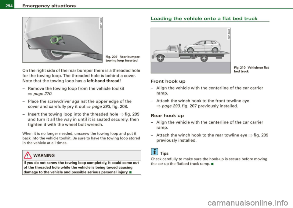
Fig. 209 Rear bumper:
towing loop inserted
On the right side of the rear bumper there is a threaded hole
for the towing loop. The threaded hole is behind a cover.
Note that the towing loop has a left-hand thread!
Remove the towing loop from the vehicle toolkit
~ page 270.
Place the screwdriver against the upper edge of the
cover and carefully pry it out~
page 293, fig. 208.
- Insert the towing loop into the threaded hole~ fig. 209
and turn it all the way in until it is seated securely, then
tighten it with the wheel bolt wrench.
When it is no longer needed, unscrew the towing loop and put it
back into the vehicle toolkit. Be sure to have the towing loop stored in the vehicle at all times.
& WARNING
If you do not screw the towing loop completely, it could come out
of the threaded hole while the vehicle is being towed causing
damage to the vehicle and possible serious personal injury. •
Loading the vehicle onto a flat bed truck
Front
hook up
N
"' :? 0:. .,
"'
Fig. 210 Vehicle on flat
bed truck
-Align the vehicle with the centerline of the car carrier
ramp.
- Attach the winch hook to the front towline eye
~ page 293, fig. 207 previously installed.
Rear hook up
-Align the vehicle with the centerline of the car carrier
ramp.
- Attach the winch hook to the rear towline eye~ fig. 209
previously installed.
[ i] Tips
Check carefully to make sure the hook -up is secure before moving
the car up the flatbed truck ramp. •