battery AUDI S3 2015 Owners Manual
[x] Cancel search | Manufacturer: AUDI, Model Year: 2015, Model line: S3, Model: AUDI S3 2015Pages: 310, PDF Size: 76.15 MB
Page 5 of 310
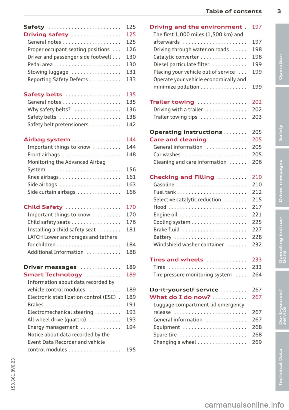
Safety . . . . . . . . . . . . . . . . . . . . . . . . . 125
Driving safety . . . . . . . . . . . . . . . . . 125
General notes . . . . . . . . . . . . . . . . . . . . 125
Proper occupant seating posit ions . . . 126
Driver and passenger side footwell . . . 130
Pedal area . . . . . . . . . . . . . . . . . . . . . . . 130
Stowing luggage . . . . . . . . . . . . . . . . . 131
R eport ing Safety Defects . . . . . . . . . . . 133
Safety belts . . . . . . . . . . . . . . . . . . . 135
General notes . . . . . . . . . . . . . . . . . . . . 135
Why safety bel ts? . . . . . . . . . . . . . . . . 136
Safety belts . . . . . . . . . . . . . . . . . . . . . 138
Safety belt p re tens ioners . . . . . . . . . . 1 42
Airbag system . . . . . . . . . . . . . . . . . 144
I mpor tan t th ings to know . . . . . . . . . . 1 44
Fr ont airbags . . . . . . . . . . . . . . . . . . . . 148
M onitoring the Advanced Airbag
System . . . . . . . . . . . . . . . . . . . . . . . . . 156
Knee airbags . . . . . . . . . . . . . . . . . . . . . 161
Side airbags . . . . . . . . . . . . . . . . . . . . . 163
Side curta in a irbags . . . . . . . . . . . . . . . 166
Ch ild Safety . . . . . . . . . . . . . . . . . . . 170
Important things to know . . . . . . . . . . 170
C hi ld safety seats ............ .... . 176
Install ing a chi ld safety seat . . . . . . . . 18 1
L A TC H L ower ancho rages and tethe rs
fo r ch ild ren . ............. .... .. . .
A ddit io nal Informa tion 184
188
Driver messages
. . . . . . . . . . . . . . 189
Smart Technology . . . . . . . . . . . . 189
I nforma tion abo ut data reco rded by
ve hicl e cont ro l mod ules . . . . . . . . . . . 189
Electron ic stabilization control (ESC) 189
Brakes . . . . . . . . . . . . . . . . . . . . . . . . . . 191
Electromechanical steering . . . . . . . . . 193
All whee l drive (quatt ro) . . . . . . . . . . . 193
Energy management . . . . . . . . . . . . . . 194
Not ice about data recorded by the
E vent Data Reco rder and ve hicle
con tro l mod ules . . . . . . . . . . . . . . . . . . 195
Table of contents 3
Driving and the environment
197
T he first 1,000 miles (1 ,500 km) and
afterwa rds . . . . . . . . . . . . . . . . . . . . . . 197
Driving through wate r on roads . . . . . 198
Catalytic converter . . . . . . . . . . . . . . . . 198
Diesel particulate filter . . . . . . . . . . . . 199
Plac ing you r vehicle ou t of service . . . 199
Operate yo ur v ehicl e economically and
min imi ze poll ution . . . . . . . . . . . . . . . . 199
Trailer towing . . . . . . . . . . . . . . . . . 202
Dr iving wit h a trailer . . . . . . . . . . . . . . 202
T rai le r tow ing t ips . . . . . . . . . . . . . . . . 203
Operating instructions . . . . . . . . 205
Care and cleaning . . . . . . . . . . . . . 205
Gener al infor mation . . . . . . . . . . . . . . 205
Car washes . . . . . . . . . . . . . . . . . . . . . . 205
Cleaning and care information . . . . . . 206
Checking and Filling . . . . . . . . . . 210
Gasoline . . . . . . . . . . . . . . . . . . . . . . . . 210
F uel tank . ... .. .... . ... ...... ... . 212
Se lective cata lytic reduction . . . . . . . . 215
Hood . . . . . . . . . . . . . . . . . . . . . . . . . . . 217
Engine o il . . . . . . . . . . . . . . . . . . . . . . . 221
Cooling system . . . . . . . . . . . . . . . . . . . 225
B rake fluid . . . . . . . . . . . . . . . . . . . . . . 227
Battery . . . . . . . . . . . . . . . . . . . . . . . . . 228
W indsh ie ld washer conta iner 232
Tires and wheels . . . . . . . . . . . . . . 233
T ires . . . . . . . . . . . . . . . . . . . . . . . . . . . 233
T ire pressu re mo nitor ing syste m 2 64
Do-it-yourself service . . . . . . . . . 2 67
What do I do now? . . . . . . . . . . . . 267
L uggage compartment lid emergency
r elease . . . . . . . . . . . . . . . . . . . . . . . . . 267
Genera l information . . . . . . . . . . . . . . 267
Eq uipment . . . . . . . . . . . . . . . . . . . . . . 268
Spare tire . . . . . . . . . . . . . . . . . . . . . . . 268
Changi ng a wheel . . . . . . . . . . . . . . . . . 269
•
•
M a N
0 > co ,...., \!) Ll'I
M Ll'I ,....,
Page 15 of 310
....,
N
0 > co
rl I.O
"' ....,
"' rl
@ Tips
Diesel engines: Due to the high efficiency
o f t hese engines, the eng ine may not al
ways reach operating temperature in cold
outs ide temperatur es. T his is normal a nd
not a cause for co nce rn.
Service interval display
The service interval display detects when your
vehicle is due for service.
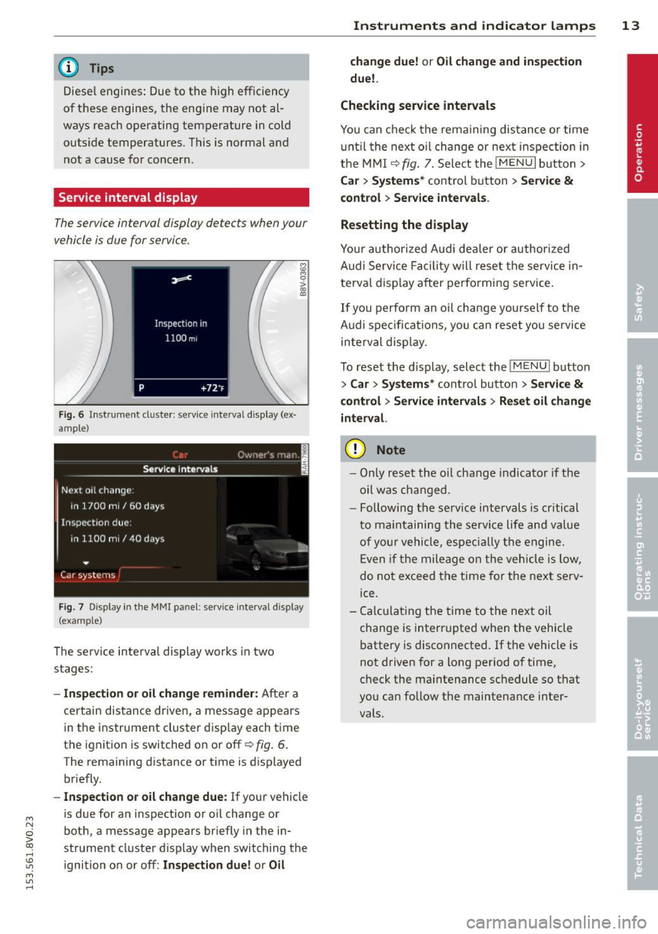
F ig . 6 In stru ment cluste r: serv ice inte rval d isp lay (ex
ample)
F ig . 7 Display in the MMI panel: service interva l display
(example)
The se rv ice interva l display wo rks in two
stages:
- In spection or oil change reminder: A ft er a
c e rt a in dis tance dr iven, a message a ppears
in t he i nstr ument cluster d isp lay each t ime
t h e i gnition is switched on or off~
fig. 6.
The remaining distance or t im e is d isplayed
br iefly.
- Inspection or oil change due : If your vehicle
is due for an inspection or o il change or
bot h, a message appears br iefly in the in
strument cluster display when switching the
ignition o n or off:
Inspection due! or Oil
Instruments and indicator lamps 13
change due! or Oil change and inspection
due!.
Checking service intervals
You can check th e rema ining dis tance o r time
u nti l the next o il change or nex t inspec tion in
t h e MM I
~ fig. 7. Sele ct the I M ENU I but to n >
Ca r > Systems * control button > Service &
control > Ser vice intervals .
Resetting the display
Y ou r auth or ized Audi dea ler or author ized
A udi Se rv ice F acili ty w ill reset the service in
te rva l display a fter performi ng service.
If you perfo rm an oil ch ange yourself to the
A udi spe cifica tions , yo u can reset you servi ce
i n terval disp lay.
T o reset t he di splay, select the
I ME NU I bu tton
> Car > System s* cont ro l button > Service &
control > Service intervals > Re set oil change
interval.
(D Note
- On ly r eset t he oil cha nge i ndicat or if th e
oi l was cha nged.
- Following t he serv ice intervals is critical
t o m ain ta ining the se rv ic e life a nd value
of your v ehicle, especi ally th e e ngine.
E ven i f the mileage on the vehicle is low,
do n ot exceed t he time fo r th e nex t serv
ice.
- C alcula ting the time to the next oil
ch ange is inter rupted whe n the vehicle
battery is disconnected. If t he vehicle is
n ot d riven for a long pe riod o f time,
check the ma intenance sc hedule so t hat
yo u ca n follow the maintena nce inter
vals.
Page 19 of 310
M N
0 > co ,...., \!) 1.1'1
M 1.1'1 ,....,
or
or
or
or
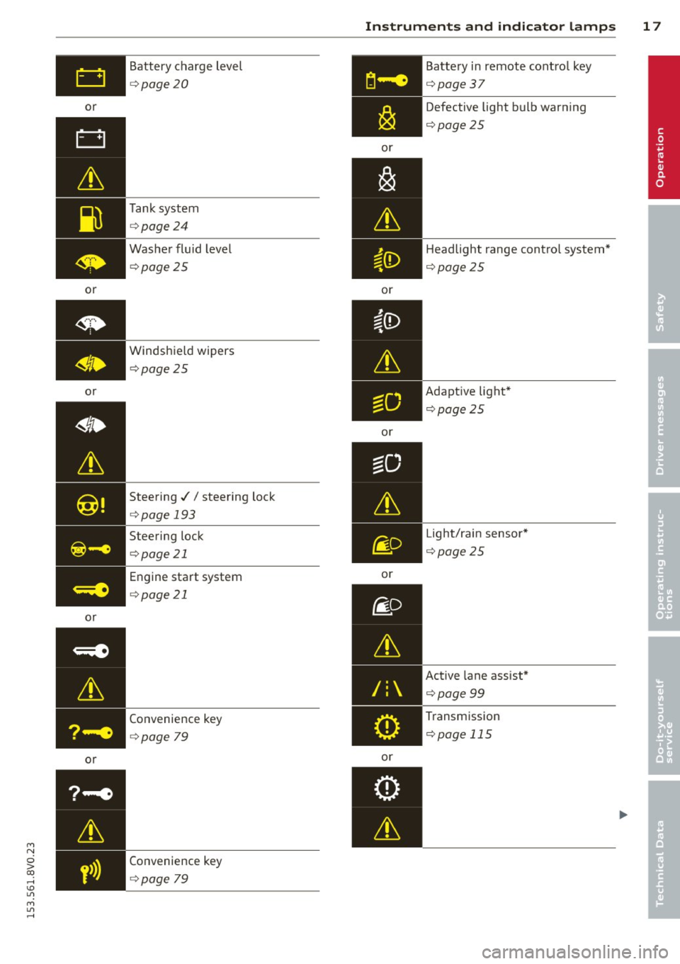
or Battery charge level
¢
page 20
Tank system
¢page 24
Washer fluid level
¢ page 25
Windshield wipers
¢page 25
Steering .//steering lock
¢page 193
Steering lock
¢p age 21
Engine start system
¢page 21
Convenience key
¢page 79
Convenience key
¢page 79
Instruments and indicator lamps 17
or
or
or
or
/:
or Battery
in remote control key
¢page37
Defective light bulb warning
¢page25
Headlight range contro l system*
¢ page25
Adaptive light*
¢page 25
Light/rain sensor*
¢page25
Active lane assist*
¢page 99
Transmission
¢page 115
•
Page 22 of 310
20 Instruments and indicator lamps
ltJ;):t :1;034 ( USA model s) / ml (Canada mod
els) Caution : Vehicle parked too steep
When t he i nd ic ator light blinks and th is mes
sage appears, t here is no t eno ugh braking
power to keep the ve hicl e from rolling . The
b rakes have overheate d. The vehicle cou ld roll
away even on a small incline .
ltJ;)i:j;lJ34 ( USA model s) / ml (Canada mod
els) Parking brake is applied
I f t his message appea rs, press t he b rake pedal
fi rst and then re lease the par king brake if nec
essa ry.
@ Tips
F or addit ional info rmation on the pa rk ing
brak e, refer t o¢
page 80.
...L Cooling system
• Switch off engine and check coolant lev
el!
T he coolant leve l is too low or the coolant
temper ature is too high .
D o not cont inue d riving and swi tc h the eng ine
o ff. C hec k the coolant leve l¢
page 225 .
-If the coolant leve l is too low, add coolant
<=> page 226 . O nly con tinue driv ing o nce the
indicator light turns off.
- If the coolant leve l is correct, the problem
may be ca used by a ma lf u nction in the radia
tor fan . D o not cont inue driv ing . See an au
t h o rized Aud i dea le r or a uth o riz ed Aud i
Se rv ic e Fa cili ty for ass ist ance.
• Coolant temperature too high! Let engine
run with vehicle stationary
Let the eng ine run at id le for a few minutes to
coo l down .
A WARNING
- Never op en the hood if you ca n se e or
h ear st ea m or coo la nt escaping from the
eng ine com pa rtm ent. This in cre ases t he
r isk of burn s. Wai t unti l you no longe r
see o r hear steam o r cool ant esca ping.
-
'
- The engine compa rtment in any vehicle
can be a dangerous area. Stop the engine
a nd allow it to cool befo re working in the
e ng ine compartment. A lways foll ow the
info rmation found in
~ page 217, Work
ing in th e engin e compartm ent.
(D Note
Do n ot cont inue dr iv ing if the . indicato r
lig ht tur ns on -this inc reases the r isk o f
engine damage.
"1::::7: Engine oil pressure
• Switch off engine! Oil pres sure too low
St op t he engine and do not cont inue drivi ng.
Check the eng ine oi l level
r=> page 223 .
- If the engine o il level is too low, add eng ine
oil
r=> page 221. Only co nti nu e driving once
the indicator light turns off.
- If the engine o il level is co rrect and the indi
cator light still turns on, turn the eng ine off
and do not cont inue driv ing . See an author
ized Aud i deale r or au tho rized Aud i Service
Facili ty for ass ista nce.
(i) Tips
The oil pressu re war ning is not an oi l level
i ndica to r. For th is reason, c hec k t he o il lev
e l reg ularly .
' 0 Alternator/battery
• Alternator fault: battery is not being
charged
The re is a malfunction in the alternator or th e
vehicle e lectr ica l system .
Drive to an authorized Audi dealer or author
ized Audi Serv ice Facility immediately . Be
ca use the v ehicl e batte ry is drain ing , turn off
all unnecessa ry el ectrical eq uipm ent such as
t h e M MI. See yo ur aut ho rized Aud i de aler o r a
qualifie d repa ir fa cili ty if the b attery ch arge
l evel is too low .
(•) low battery charge: Battery will be
charged while driving
Page 31 of 310
....,
N
0 > co
rl I.O
"' ....,
"' rl
.. To switch between the tabs, p ress the rocker
button ® to the left or right~
fig. 10.
.. To access additional information be low or
above, rotate the thumbwheel @down or
up .
.. To confirm a selection, press the thumb
wheel @.
.. To select a function programmed to a steer
ing wheel button, p ress the button@. Fo r
addi tional informa tion, see¢
page 29, As
signing a function to the programmable
steering wheel button
Calling up the Vehicle functions
.. Se lect the first tab w ith the button @ .
.. Press the button @. The
V eh icle fun ction s
menu is displayed 9fig. 11 .
.. To select a menu item, turn and press the
th umbwheel @.
Resetting values to zero
.. In the Vehicle function s menu, select On·
board computer or Efficien cy prog ram .
.,. Se lect a v alue in the desired trip computer
or in the efficiency program .
.. To reset the values in a memo ry, press and
hold the thumbwhee l@ for one second.
Recalling indicator lights and messages
.. Press the button (!) repeated ly until the Q
tab appears.
The
Q tab is only vis ible when there is a mal
function.
Assigning a function to the programmable steering wheel button
.. Select: the I MENU ! button >Car > Sy stem s*
control button > Vehi cle setting s > Stee ring
wheel button progr amming .
The Q tab is only vis ible when there is at
least one indicator light or message dis
p layed.
(0 Tips
- If the vehicle battery is d iscon nected, all
memo ry valu es a re e rased.
Dr iver in formation system 29
- In formation on the efficiency program
¢page 29 .
-There is more information on the multi
function stee ring wheel in the MMI *
owne r's man ual.
Boost indicator
Applies to vehicles: with boost pressure indicator
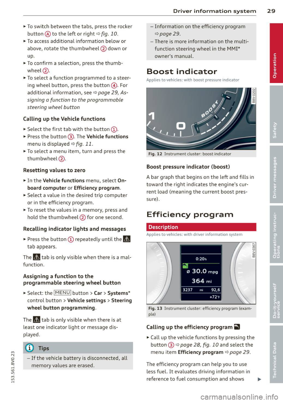
Fig. 12 Instrument cluste r: boost indicator
Boost pressure indicator (boost)
A bar graph that begins on the left and fills in
toward the right indicates the eng ine's cur
rent load (m ean ing the current boos t pres
su re).
Efficiency program
Description
Applies to vehicles: with driver information system
Fig. 1 3 In strument cluster: efficie ncy program (exam
ple)
Calling up the efficiency program~
.. Call up the vehicle functions by pressing the
button ®
9 page 28, fig. 10 and select the
menu item
Efficiency p rogram ¢page 29 .
The efficiency program can he lp you to use
less fuel.
It evaluates driving information in
reference to fuel consumption and shows .,..
Page 39 of 310
LED and batteries in the remote control
key
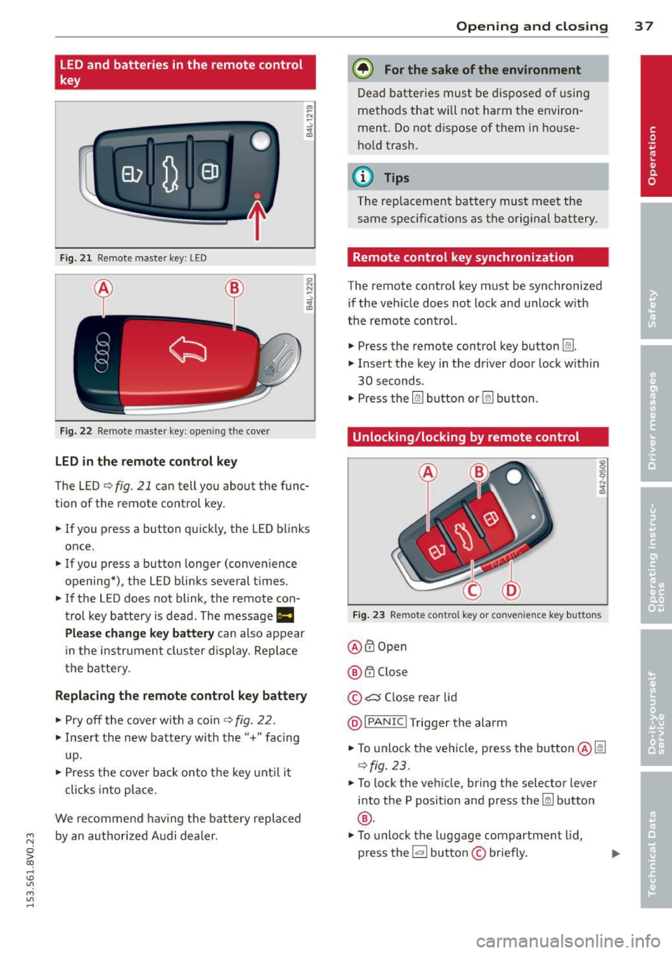
Fig. 2 1 Remote master key: LED
Fig. 22 Remote master key: opening the cove r
LED in the remote control key
The LED¢ fig. 21 can tell you about the func
tion of the remote control key .
.. If you press a button quickly, the LED blinks
once .
.. If you press a button longer (convenience
opening*) , the LED blinks several times .
.. If the LED does not blink , the remote con
trol key battery is dead. The message
Ill
Plea se change key battery can also appear
in the instr ument cluster display. Replace
the battery.
Replacing the remote control key battery
.. Pry off the cover w ith a coin ¢ fig . 22 .
.. Insert the new battery with the"+" fac ing
up.
.. Press the cover back onto the key until it
clicks into place .
We recommend having the battery replaced
~ by an authorized Audi dealer.
0 > co
rl I.O
"' M
"' rl
Opening and closing 3 7
@) For the sake of the environment
Dead batteries must be disposed of using
methods that will not harm the environ
ment. Do not dispose of them in house
hold trash .
{!) Tips
The rep lacement battery must meet the
same specifications as the origina l battery.
Remote control key synchronization
The remote control key must be synchronized
if the veh icle does not lock and unlock w ith
the remote control.
.. Press the remote control key button
Im .
.. Insert the key in the driver door lock w ith in
30 seconds .
"' Press the
l@J button or~ button .
Unlocking/locking by remote control
Fig. 23 Remote control key or conve nien ce key buttons
@ffi Open
@ 6".i Close
© c:s Close rear lid
@I PANIC I Trigger the alarm
.. To unlock the vehicle, press the button@lm
¢fig.23 .
"'To lock the veh icle, bring the selector lever
into the P posit ion and press the~ button
®·
"'To unlock the luggage compartment lid,
press the~ button
© briefly.
Page 41 of 310
....,
N
0 > co
rl I.O
"' ....,
"' rl
WARNING
----Read and following all WARNINGS. ¢ & in
Key set on page 35
@ Tips
If your vehicle is left standing for a long
period of time, note the following:
- The proximity sensor switches off after a
few days to save energy. You then have
to pull once on the door handle to unlock
the vehicle and a second time to open it.
- To prevent the battery from draining and
to retain the starting ability of yo ur vehi
cle as long as possible, the energy man
agement system gradua lly tuns off un
necessary convenience functions You
may not be able to unlock your vehicle
using the convenience key .
- For an explanation on conformity with
the FCC regulations in the United States
and the Industry Canada regulations, re
fer to ¢page
292 .
Unlocking/locking with the key
In the event that the power locking system
fails, the driver's door can locked and un
locked using the door lock .
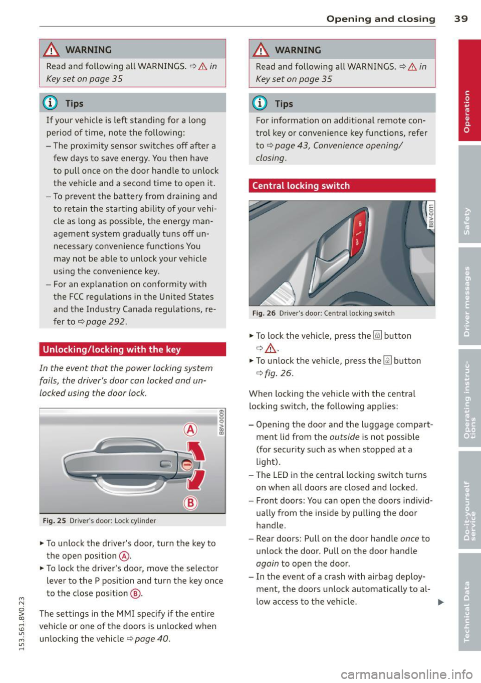
Fig. 25 Driver 's door: Lock cy linder
.,. To unlock the driver's door, turn the key to
the ope n position @.
en 0 g
~
.,. To lock the driver's door, move the se lector
lever to the P position and turn the key once
to the close position
@ .
The settings in the MMI specify if the entire
vehicle or one of the doors is un locked when
unlocking the vehicle¢ page 40 .
Opening and closing 39
A WARNING
Read and following all WARNINGS. ¢ & in
Key set on page 35
(D Tips
For information on additional remote con
trol key or convenience key functions, refer
to
¢ page 43, Convenience opening/
closing.
Central locking switch
Fig. 26 Drive r's doo r: Centra l locki ng sw itch
.,. To lock the vehicle, press the@! button
¢.&, .
.,. To unlo ck the vehicle, press the @J button
¢fig.
26.
When locking the vehicle with the central locking switch, the following applies:
- Opening the door and the Luggage compart
ment lid from the outside is not possible
(for security such as when stopped at a
light).
- The
LED in the central locking switch turns
on when all doors are closed and locked .
- Front doors: You can open the doors ind iv id
ually from the inside by pulling the door
handle.
- Rear doors: Pull on the door handle once to
unlock the door. Pull on the door hand le
again to open the door .
- In the event of a crash w ith airbag deploy·
ment, the doors unlock automatically to al-
low access to the vehicle. ..,.
Page 46 of 310
44 Opening and clo sing
• Hold the key in the driver's door lock until all
windows and the panorama sunroof* have
reached the desired position .
Conveni ence closing
• Hold the key in the d river's door lock i n the
lock pos ition until a ll wi ndows and the pan
o rama sunroo f* are closed .
Convenience closing with the convenience
key*
• To uch the sensor* on one of the front door
h and les and cont in u e touching it unt il all of
the windows and the panorama s unroof* are
closed . Do not place your hand in the door
hand le when doing th is.
Adjusting the convenience opening in the
MMI
• Se lect : the I MENU ! button> Car> Systems *
control button > Vehicle sett ings > Central
locking > Long -press to open windows
To enab le convenience opening of the win -
dows and the roo f*, the
Front windows , Rear
w indows *
and Roof* functions must be
sw itched
On .
A WARNING
-Never close the windows or pano rama
sunroof* carel essly or in an uncontro lled
m ann er, be cause th is increases the risk
o f i njury.
- Fo r se curity reasons, the windows can
only be opened with the remote c ontro l
k ey at a maxim um dis tance of ap proxi
ma tely 6 feet ( 2 meters) from the ve hi
cle .
- Pa y att ention when using the lock cyli n
der to close the windows and t he panora
ma sunroof* so that no one is pinche d.
Clos ing stops whe n the key is moved into
the start ing pos ition.
Correcting power window malfunctions
After disconnecting the vehicle battery , the
one-touch up and down feature must be acti vated again .
• Pull the power window switch u ntil the win
dow is completely ra ised .
• Release the sw itch and pull it agai n for at
l e ast one s econd .
Panorama sunroof
Description
Applies to vehicles: with panoramic sunroof
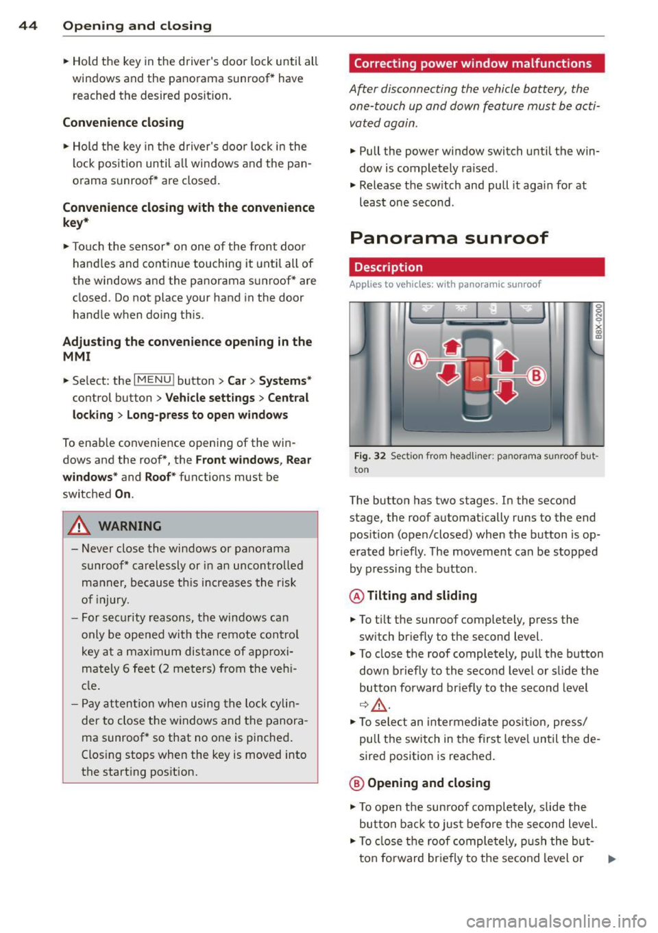
Fig. 32 Sect io n fr om headli ner: pano ra m a s unroof but
to n
The butto n has two stages . In the second
stage, the roof automat ically runs to the end
pos ition (open/closed) when the button is op
era ted br iefly . T he movement ca n be s topped
by pressing the b utton .
@Tilting and sliding
• To t ilt the sunroof completely , press the
sw itch br iefly to the second level.
• To close t he roof completely, pu ll the button
down b riefly to the seco nd leve l or s lide the
button forward br iefly to the s econd level
~~-
.. To se le ct an in termedia te pos it ion , press/
pull t he sw itch in the firs t leve l until the de
sired position is reached .
@ Opening and closing
• To open t he su nroof completely, sli de the
button bac k to ju st befo re the second level.
• To close t he roof comple tely, p ush the but-
t on fo rward br ie fly to the se cond level or .,..
Page 63 of 310
....,
N
0 > co
rl I.O
"' ....,
"' rl
CD Note
To prevent damage to the socket, only use
the correct type of plugs.
- Never connect devices that generate
electrical power such as so lar panels or a
battery charger to the 12 volt socket.
They can damage the vehicle electrical
system.
- To prevent damage to the socket, only
use the correct type of plugs.
(D Tips
The vehicle battery drains when accesso
ries are turned on but the engine is off .
Storage
Cup holders
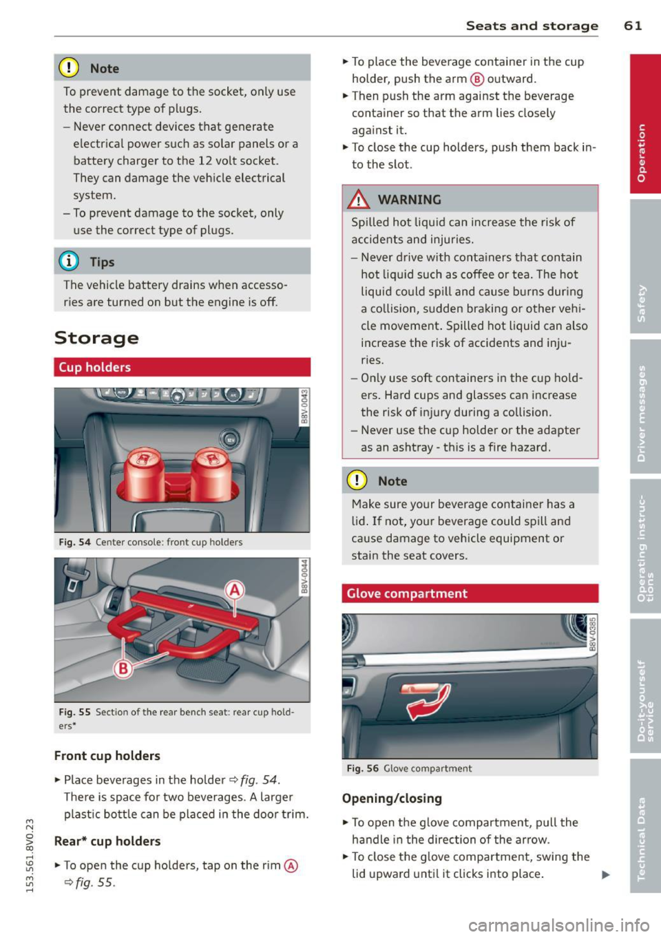
Fig. 54 Center console : front cup holders
Fig. 55 Sectio n of the rear benc h seat: rear cup ho ld
ers*
Front cup holders
.. Place beverages in the holder ¢ fig. 54.
There is space for two beverages. A larger
plastic bottle can be placed in the door trim.
Rear* cup holders
.. To open the cup holders, tap on the rim@
¢fig. 55 .
Seats and storage 61
.. To place the beverage container in the cup
holder, push the arm @ outward.
.. Then push the arm against the beverage
container so that the arm lies closely
against it.
.. To close the cup holders, push them back in
to the slot.
.&_ WARNING
Spilled hot liqu id can increase the risk of
accidents and injuries.
- Never drive with containers that contain
hot liquid such as coffee or tea. The hot
liquid could spil l and cause burns during
a collision, sudden braking or other vehi
cle movement . Spilled hot liquid can also
increase the risk of accidents and inju
ries.
- Only use soft containers in the cup hold
ers. Hard cups and glasses can increase
the risk of injury during a collision.
- Never use the cup holder or the adapter
as an ashtray -th is is a fire hazard.
CD Note
Make sure your beverage contai ner has a
lid. If not, your beverage could spill and
cause damage to vehicle equipment or
stain the seat covers.
Glove compartment
Fig. 56 Glove compartment
Opening/closing
.. To open the glove compartment, pull the
handle in the direction of the arrow.
.. To close the glove compartment, swing the
.
lid upward until it clicks into place. II>
Page 74 of 310
7 2 Warm and cold
& WARNING
You should not use the rec irculation mode
for an extended per iod since no fresh air is
drawn in . With the ai r-conditioning switch
ed off, the windows can fog up, which in
c reases t he risk of an ac cident.
Adjusting the air vents
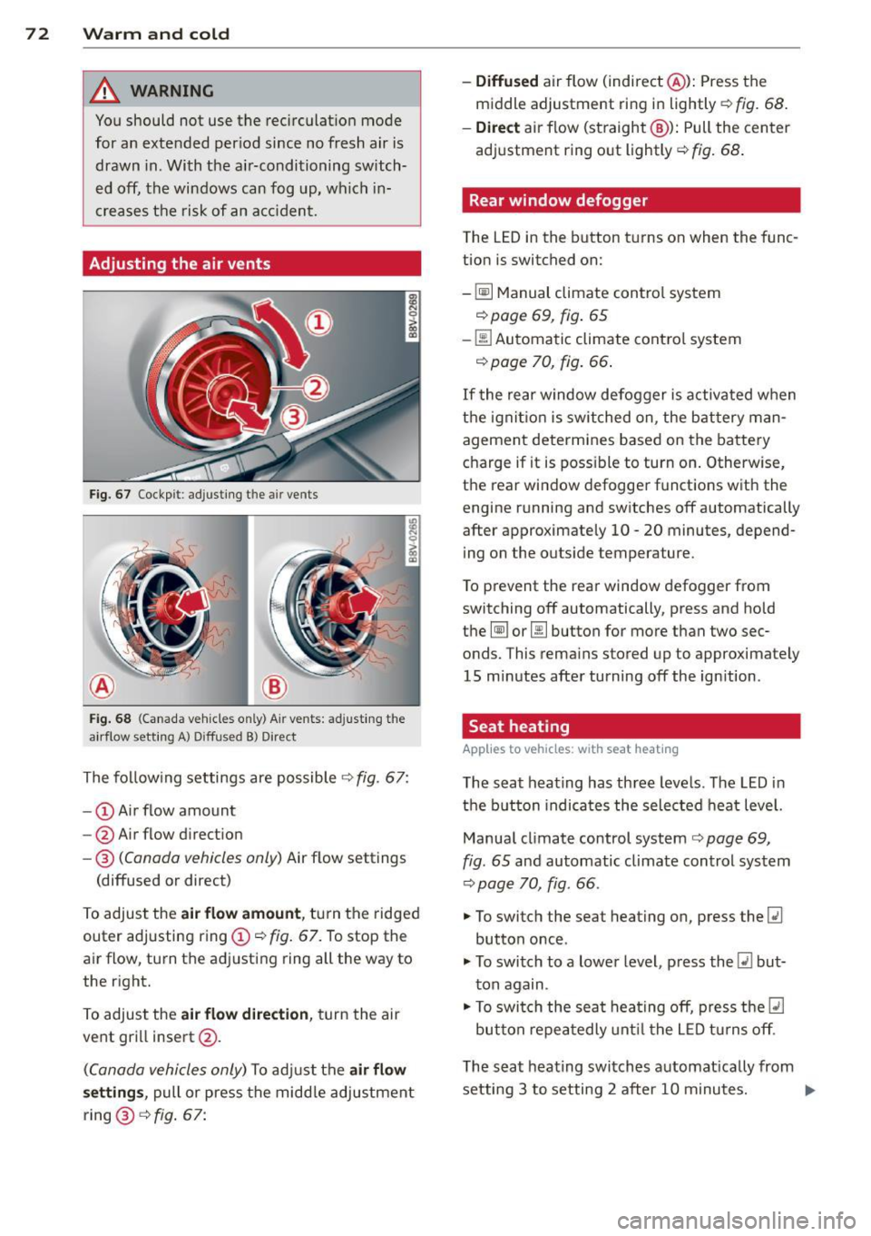
Fig. 67 Cockp it : adjust ing the a ir vents
®
Fi g. 6 8 (Canada ve hicles o nly) A ir ve nts : ad just ing t he
a irflow sett ing A ) D iffused B ) Direct
The fo llow ing settings are possible ¢ fig. 67:
- © Airflow amount
- @ Air flow d irect ion
- @
(Canada vehicles only) Air f low settings
(diffused or direct)
To adjust the
air flow amount , tu rn the ridged
outer adj usting ring©
c::> fig. 67. To stop the
air flow, turn t he adjusting ring all the way to
the right.
To adjust the
air flow direction , turn the air
ve nt gri ll insert @.
(C anada vehicles only) To ad just the air flow
setting s,
pull or press the midd le adjustment
ring @¢
fig. 67:
- Diffused air flow (indirect @): Press the
middle adjustment ri ng in lightly
c::> fig. 68 .
- Direct
air f low (st raight @): Pull the center
ad justment ring o ut lightly ¢
fig. 68 .
Rear window defogger
The LED in the button t urns on when the func
tion is switched on:
-
~ M anual climate contro l system
c::> page 69, fig . 65
-00 Automatic climate contro l system
c::> page 70, fig . 66.
If the rear w indow defogger is activated w hen
t h e igni tion is switched on, the bat tery man
agement determines based on the battery
c h arge if i t is poss ible to turn on . Otherw ise,
the rear window defogge r funct ions w it h the
engine running and switches off automatically
after approximately 10 -20 minutes, depend
i ng on the outs ide temperature .
T o p revent the rear window defogger f rom
switching off automatically, press and hold
t h e
@ii or 00 button for more than two sec
onds. This rema ins stored up to approxima tely
15 minutes afte r turning off the ign ition .
Seat heating
Applies to veh icles : w it h seat heat ing
The seat heating has th ree leve ls. The LED in
the b utt on indica tes the sele cted heat leve l.
Manua l climate control system
c::> page 69,
fig . 65 and automatic climate control system
c::> page 70, fig . 66.
"' To switch the seat heating on, press the
lt:J
button once .
"' To swi tch to a lower level , press the
lt:I but
ton again .
"' To swi tch the sea t heating off, press the
lt:J
but ton re peat edly unt il t he L ED turns off .
T he seat heating swi tches a utomat ica lly from
setting 3 to setting 2 after 10 minutes.
Iii>