display AUDI S3 2015 Owners Manual
[x] Cancel search | Manufacturer: AUDI, Model Year: 2015, Model line: S3, Model: AUDI S3 2015Pages: 310, PDF Size: 76.15 MB
Page 11 of 310
M N
0 > co ...... \!) ..,.,
M ..,., ......
CD
@
®
©
®
®
(J)
®
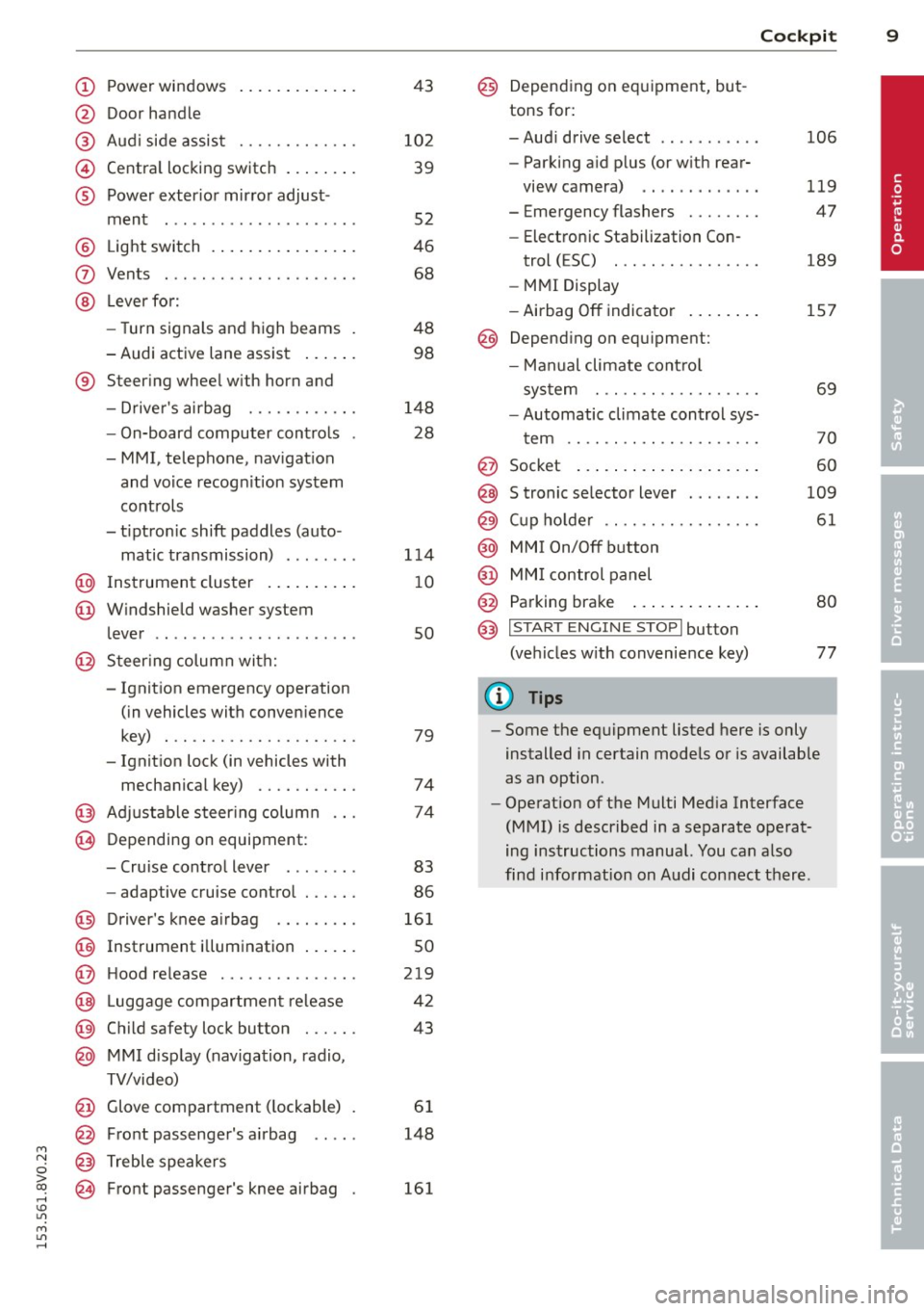
Power windows
Door handle
Aud i side assist
........ .... .
Centra l locking switch ... .. .. .
Powe r exter ior mirror adjust
ment
.. ... .............. ..
Light switch
Vents
L ever fo r:
- Turn signals and high beams
- Audi active lane assist ... .. .
® Steer ing wheel w ith horn and
- Drive r's airbag ....... .. .. .
- On-board computer controls
- MMI, telephone, nav igat ion
and voice recogn it ion system
controls
- tiptron ic shift paddles (auto-
matic transmission) ....... .
@ Instrument cluster .. ... .. .. .
@ W indshield washer system
l ever
' .. ... .............. . .
@ S teer ing column with:
- Ignit ion emergency operation
(in vehicles with conven ience
key) . .. ................. .
- Ignit ion lock (in vehicles with
mechanical key) ...... .. .. .
@ Adjustable s teer ing column
@ Depending on equipment :
- Cruise contro l lever . ...... .
- adaptive cruise contro l ... .. . 4
3
10 2
39
52
46
68
48 98
148 28
1 14
1 0
so
79
74
74
83
86
@ D river's knee a irbag . . . . . . . . . 161
@ Instrument i llumination . . . . . . 50
@ H ood re lease . . . . . . . . . . . . . . . 219
@ Lugg age compartmen t release 42
@ Child safety lock button . . . . . . 43
@ MMI d isp lay (navigation , radio,
TV/video)
@ Glove compartment ( lockable)
@ Front passenger's airbag .. .. .
@ Treble speakers
@ Front passenger's knee airbag 61
148
161
Cockpi t 9
@) Depending on eq uipment, but
tons for:
- Aud i drive select
- Parking a id p lus (or w ith rear-
view camera) .. . ... ...... .
- Emergency flashers ....... .
- Electron ic Stabilization Con-
trol ( ESC) . .. .... ........ .
- MMI Display
- Airbag
Off indicator ..... .. .
@ Depend ing on equ ipment:
- Manual climate cont ro l
system
- Automatic climate contro l sys
t em
. . .. .. .. .... .........
@ Socket
@ S tronic se lector lever ....... .
@ Cup ho lder .. .. .. . ......... .
@ MMI On/Off button
@ MM I control panel
@ Parking brake ... . ... ...... .
@ I START ENGI NE STOPI button
(ve hicles w ith convenience key)
(D Tips
106
119
47
189
157
69
70
60
109
61
80
77
- Some the eq uipment listed here is only
installed in certain models or is available
as an option.
- Operat ion of the Multi Med ia Interface
(MMI) is described in a separate operat
ing instructions manual. You can a lso
find info rmation on A udi con nect ther e.
•
Page 12 of 310
10 Instruments and indicator lamps
Instruments and indicator lamps
Instruments
Instrument cluster overview
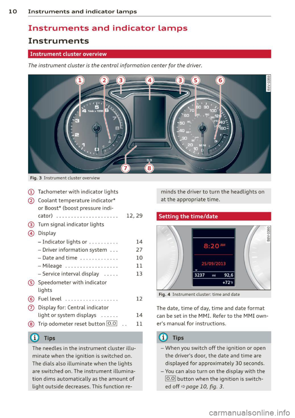
The instrument cluster is the central information center for the driver.
Fig. 3 Instrument cl uster ove rv iew
(D Tachometer with ind icator lights
@ Coolant temperature indicator*
or Boost* (boost pressure indi -
cator) . . . . . . . . . . . . . . . . . . . . .
12, 29
® Turn signal indicator lights
© Display
- Indicator lights or . . . . . . . . . .
14
- Driver information system . . . 27
- Date and time . . . . . . . . . . . . .
10
- Mileage . . . . . . . . . . . . . . . . . . 11
- Service interval display . . . . . 13
® Speedometer with indicator
lights
@ Fuel level . . . . . . . . . . . . . . . . . . 12
(J) Display for: Central indicator
light or system displays . . . . . .
14
@ Trip odometer reset button 10 .0 1 11
(!) Tips
The needles in the instrument cluster illu
minate when the ignition is switched on.
The dials also illuminate when the lights
are switched on . The instrument illumina
tion dims automatically as the amount of light outside decreases . This funct ion re- minds
the driver to turn the headlights on
at the appropriate time.
Setting the time/date
Fig. 4 Instrument cluster: time and date
The date, time of day, time and date format
can be set in the MMI. Refer to the MMI own
er's manual for instructions.
@ Tips
-When you switch off the ignition or open
the driver's door, the date and time are
displayed for approximately
30 seconds .
- You can also turn on the display with the
!O.O l button when the ignition is switch
ed
off ~page 10, fig. 3 .
Page 13 of 310
....,
N
0 > co
rl I.O
"' ....,
"' rl
Tachometer
The tachometer displays the engine speed in
revolutions per minute .
The beginning of the red zone in the tachome
ter indicates the maximum permiss ible en
g ine speed for all gears once the engine has
been broken in and when it is warmed up to
operat ing temperature. You shou ld select the
"D/S" (Drive) selecto r lever pos ition or take
your foot off the accelerator peda l before
reaching th is area .
It is best to avoid high engine speeds, even
when dr iv ing in tiptron ic mode ~
page 114 .
(D Note
The tachometer needle
(D ¢ page 10,
fig. 3
shou ld only be in the red zone brief
ly: otherwise, this increases the risk of en
gine damage.
@) For the sake of the environment
Upshift ing early helps you to save fuel and
reduce operating no ise.
Odometer
Fig. S In strument cl uster: odo meter an d reset butto n
The distance driven is shown in miles "mi" or
in kilometers "km" . The measurement units
(mi les "mi"
I kilometers "km") can be
changed in the MMI. For more info rmation,
refer to your M MI operating instructions.
Odometer /trip odom eter
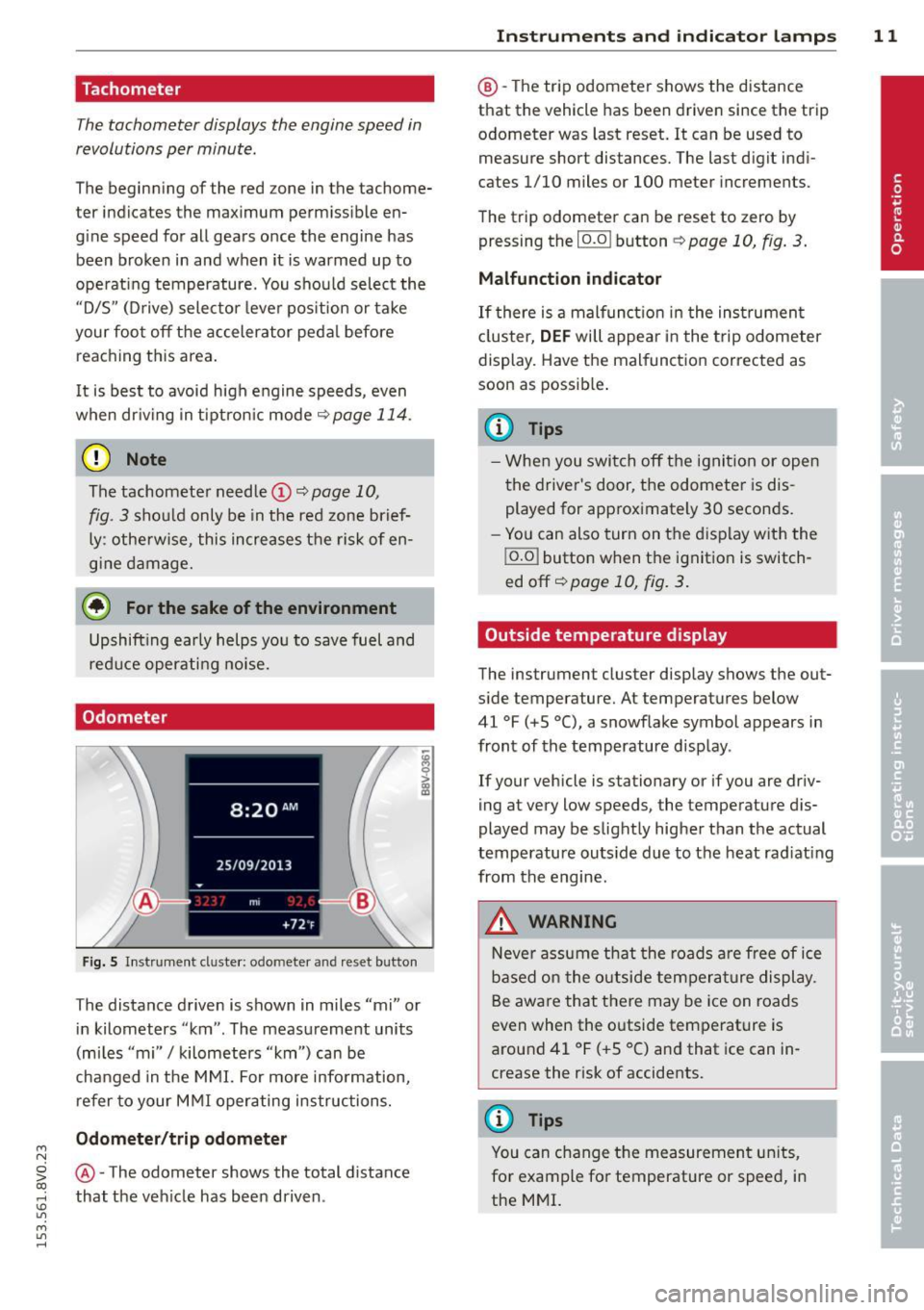
@ -The odometer shows the total d ista nee
that the veh icle has been driven .
Instrument s an d indi cat or l amp s 11
@ -The trip odometer shows the distance
that the vehicle has been driven since the trip
odometer was last reset. It can be used to measure short distances. The last digit ind i
cates 1/10 miles or 100 meter increments .
The trip odometer can be reset to zero by pressing the
I o.o I button ¢ page 10, fig. 3.
Malfunction indicator
If there is a malfunct io n in the ins trumen t
cl uster,
DEF will appear in the trip odometer
display. Have the malfunction corrected as
soon as possib le .
(D Tips
- Whe n you switch off the ignit ion or open
the driver's door, the odometer is dis
played for approximately 30 seconds.
- Yo u can also turn on the display with the
j o.o j button when the ignition is switch
ed off~
page 10, fig . 3.
Outside temperature display
The instrument cluster display shows the out
s ide temperature. At temperatu res below
41 °F (+S °C), a snowf lake symbol appears in
front of the temperature display .
If your vehicle is stationary or if you are driv
ing at very low speeds, the temperature d is
played may be slightly higher than the actual
temperatu re outs ide due to the heat rad iating
from the engine.
,&. WARNING
N eve r assume that the roads a re free of ice
based on the outside temperature display.
Be awa re that there may be ice on roads
even when the outside temperature is
around 41 °F ( +S °C) and that ice can in
crease the risk of accidents.
(D Tips
You can change t he measurement un its,
for example fo r temperature or speed, in
the MMI.
Page 14 of 310
12 Instrum ent s and indicator lamp s
Fuel level
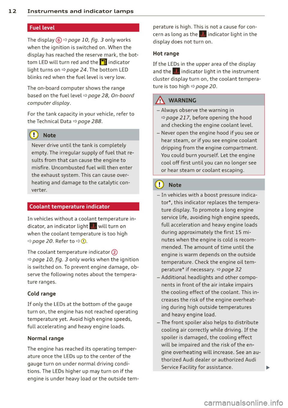
The display@ Q page 10, fig. 3 only works
when the ignition is sw itched on . When the
d isplay has reached the reserve mark, the bot
tom LED wi ll turn red and the
tD indicator
light turns on
Q page 24 . The bottom LED
blinks red when the fue l level is very low .
The on -board computer shows the range
based on the fuel leve l
Q page 2 8, On-board
computer display.
F or the tank capac ity in yo ur vehicle , refer to
the Tec hnical Data
Q page 288.
CJ) Note
Never d rive until the tank is completely
empty. The irregular supp ly of fuel that re
sults from that can cause the engine to
misfire. Uncombusted f uel will then enter
the exha ust system. This can cause over
heating and damage to the catalytic con
verter .
Coolant temperature indicator
In vehicles without a coolant temperature in
d icator , an indicator l ight . will turn on
when the coolant temperature is too h igh
Q page 20. Refer to Q Q) .
The coolant temperature ind icator @
c::> page 10, fig . 3 only works when the ignition
is switched on . T o prevent engine damage, ob
serve the fo llow ing notes about the tempe ra
ture ranges.
Cold range
If only the LEDs at the bottom of the gauge
turn on, the engine has not reached operat ing
temperature yet . Avoid high engine speeds,
fu ll acce le rat ing and heavy engine loads.
Norm al range
The engine has reached its operating temper
ature once the LEDs up to the center of the
gauge turn on under normal driving condi
tions. The L EDs higher up may turn on if the
engine is under heavy load or the o uts ide tern- perature is h
igh. This is not a cause for con
cern as long as th e . indicator light in the
display does not turn on.
Hot range
If the L EDs in the upper area of the disp lay
and the. indicator light in the instrument
cluster disp lay t urn on , the coo lant tempera
ture is too high
c::> page 20.
A WARNING
I-
- Always observe the warn ing in
c::> page 217, before opening the hood
and checking the engine coolant level.
- Never open the eng ine hood if you see or
hear steam, or if you see engine coo lant
dripping from the engine compartment.
You could burn yourse lf . Let the engine
coo l off f irst unti l yo u can no longe r see
or hea r steam or coolan t escap ing.
Q) Note
- In vehicles w ith a boost pressure indica
to r*, this indicator replaces the tempe ra
t ur e display. To promote a long engine
service life, avoiding h igh engine speeds,
full acceleration and he avy eng ine lo ads
during approximately the first 15 m i
nutes when the engine is co ld is recom
mended. The amount of time until the
eng ine is warm depends on the outside
temperat ure. Check the engine oil tem
perature* if necessary.
c::> page 32
- Add itiona l head lights and other compo
nents in front of the air intake impairs
the cooling effect of t he coolant. This in
creases the risk of the engine overheat
ing during high outs ide temperatures
and heavy eng ine load.
- T he front spoiler also he lps to d istr ibute
cooling ai r correctly wh ile driving. If the
spoiler is damaged, the coo ling effect
w ill be imp aired and the risk of the en
gine overhea ting will increase . See an au
thorized Audi dealer or autho rized Audi
Service Facility for assistance . ...,
Page 15 of 310
....,
N
0 > co
rl I.O
"' ....,
"' rl
@ Tips
Diesel engines: Due to the high efficiency
o f t hese engines, the eng ine may not al
ways reach operating temperature in cold
outs ide temperatur es. T his is normal a nd
not a cause for co nce rn.
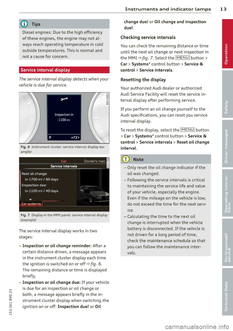
Service interval display
The service interval display detects when your
vehicle is due for service.
F ig . 6 In stru ment cluste r: serv ice inte rval d isp lay (ex
ample)
F ig . 7 Display in the MMI panel: service interva l display
(example)
The se rv ice interva l display wo rks in two
stages:
- In spection or oil change reminder: A ft er a
c e rt a in dis tance dr iven, a message a ppears
in t he i nstr ument cluster d isp lay each t ime
t h e i gnition is switched on or off~
fig. 6.
The remaining distance or t im e is d isplayed
br iefly.
- Inspection or oil change due : If your vehicle
is due for an inspection or o il change or
bot h, a message appears br iefly in the in
strument cluster display when switching the
ignition o n or off:
Inspection due! or Oil
Instruments and indicator lamps 13
change due! or Oil change and inspection
due!.
Checking service intervals
You can check th e rema ining dis tance o r time
u nti l the next o il change or nex t inspec tion in
t h e MM I
~ fig. 7. Sele ct the I M ENU I but to n >
Ca r > Systems * control button > Service &
control > Ser vice intervals .
Resetting the display
Y ou r auth or ized Audi dea ler or author ized
A udi Se rv ice F acili ty w ill reset the service in
te rva l display a fter performi ng service.
If you perfo rm an oil ch ange yourself to the
A udi spe cifica tions , yo u can reset you servi ce
i n terval disp lay.
T o reset t he di splay, select the
I ME NU I bu tton
> Car > System s* cont ro l button > Service &
control > Service intervals > Re set oil change
interval.
(D Note
- On ly r eset t he oil cha nge i ndicat or if th e
oi l was cha nged.
- Following t he serv ice intervals is critical
t o m ain ta ining the se rv ic e life a nd value
of your v ehicle, especi ally th e e ngine.
E ven i f the mileage on the vehicle is low,
do n ot exceed t he time fo r th e nex t serv
ice.
- C alcula ting the time to the next oil
ch ange is inter rupted whe n the vehicle
battery is disconnected. If t he vehicle is
n ot d riven for a long pe riod o f time,
check the ma intenance sc hedule so t hat
yo u ca n follow the maintena nce inter
vals.
Page 16 of 310
14 Instruments and indicator lamps
Indicator lights
Description
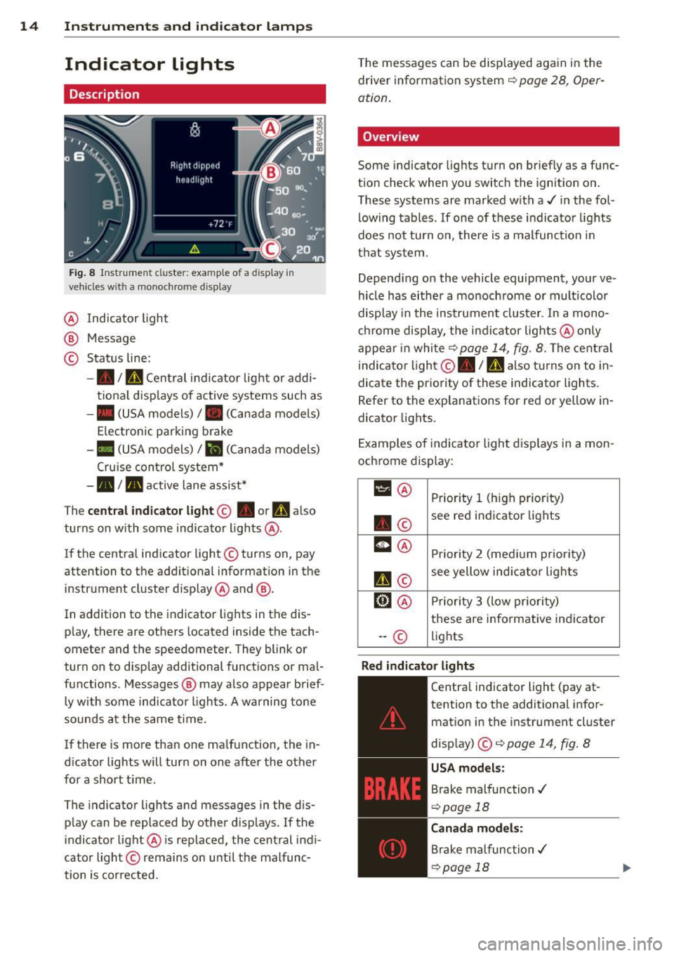
Fig. 8 Instrument cl uster: example of a display in
vehicles wit h a mo nochrome display
@ Indicator light
@ Message
© Status line:
-• ID Central indicator light or addi
tional displays of active systems such as
- • (USA models)/ . (Canada models)
Electronic parking brake
-II (USA models)/ ii (Canada models)
Cruise control system*
-• I. active lane assist*
The
central indicator light@ • or ml also
turns on with some indicator lights@.
If the central indicator light @turns on, pay
attention to the additional information in the
instrument cluster d isplay @and @.
In addition to the indicator lights in the dis
play, there are others located inside the tach
ometer and the speedometer. They blink or
turn on to display additional functions or mal
functions . Messages @ may also appear brief
ly with some indicator lights. A warning tone
sounds at the same time.
If there is more than one malfunction, the in
d icator lights will turn on one after the other
for a short time.
The indicator lights and messages in the dis
play can be replaced by other displays . If the
indicator light@ is replaced, the central indi
cator light © remains on until the malfunc
tion is corrected. T
he messages can be displayed again in the
driver information system ¢
page 28, Oper
ation.
Overview
Some indicator lights turn on briefly as a func
tion check when you switch the ignition on.
These systems are marked w ith a./ in the fol
lowing tables. If one of these indicator lights
does not tu rn on, there is a malfunction in
that system .
Depend ing on the vehicle equipment, your ve
hicle has either a monochrome or multicolor
display in the instrument cluster . In a mono
chrome display, the indicator lights @only
appear in white
¢ page 14, fig. 8. The central
indicator light ©. /
n also turns on to in
dicate the priority of these indicator lights.
Refer to the explanations for red or yellow in
dicator lights.
Examples of indicator light displays in a mon
ochrome display:
11 @ Priority 1 (high priority)
. © see red indicator lights
m
@ Priority 2 (medium priority)
II©
see yellow indicator lights
@l @ Priority 3 (low pr iority)
these are informative indicator
-- © lights
Red indicator lights
-------------
Central indicator light (pay at-
tention to the additional infor
mation in the instrument cluster
display) ©¢
page 14, fig. 8
USA models:
Brake malfunction ./
¢page 18
Canada models:
Brake malfunction./
¢page 18
Page 25 of 310
M N
0 > co ,...., \!) 1.1'1
-If the warning light EiJ or the warning
light
11111 ) w ith the message B ra ke
pads !
comes on in the instrument cluster
display, immediately contact your au
thorized Aud i dealer or qualified work
shop to have a ll brake pads checked or
replaced if necessary.
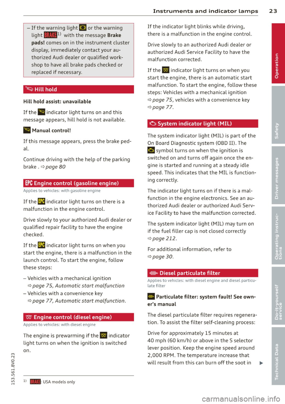
· ~ Hill hold
Hill h old ass is t: un availabl e
If the II indicator l ight turns on and this
message appears, hill hold is not available.
II Manu al control!
If this message appears, press the brake ped
al.
Continue dr iving with the help of the parking
brake .
¢ page 80
EPC Engine control (gasoline engine)
Applies to vehicles: with gasoline engine
If the [ID indicator light turns on there is a
malfunct ion in the engine control.
Drive s low ly to your author ized Audi dealer or
qua lified repai r facility to have the engine
checked.
If the ~ indicato r ligh t turns on when you
start the engine, there is a mal func tion in the
l aunch cont ro l. To start the engine, follow
these steps:
- Vehicles with a mechanical ignition
¢ page 75, Automatic start malfunction
-Vehicles with a conven ience key
¢ page 77, Automatic start malfunction .
W Engine control (diesel engine)
Applies to vehicles: with diesel engine
The engine is prewarming if the II indicato r
light turns on when the ignition is switched
on.
M
~ 1) - : USA mod els only
In strum ent s an d indicator lamp s 23
If the indicator light blinks while d riving,
there is a ma lfunction in the engine control.
D rive slowly to an authorized Aud i dea ler or
a uthorized Aud i Service Fac ility to have the
malfunction corrected.
If the II ind icator light turns on when you
star t the eng ine, the re is an automa tic start
malfunction . T o start the eng ine , fo llow these
steps: Vehicles with a mechanical ignition
¢ page 75, vehicles with a convenience key
¢ page 77.
a System indicator light (MIL)
The system indicator light (MIL) is part of the
On Board Diagnostic system (OBD II). The
II symbol turns o n when the ignition is
switched on and turns off again once the en gine is started and run ning at a steady id le
speed . This indicates that the M IL is function
ing correct ly.
The ind icator light turns on if there is a mal
functio n in the eng ine e lectronics. See an au
tho rized Audi dea le r or authorized Audi Serv
ice Facili ty to have the malf unc tion corrected.
The system indicator light (MIL) may turn on i f the fue l filler cap is not closed co rrectly
¢ page 212.
For additional information, refer to
¢ page 30 .
®-~ Diesel particulate filter
Applies to veh icles: w ith diese l engine and d iese l particu
late filter
• Particulate filter: s ystem fault! See own
er's manual
The diese l particu late filter requires regenera
tion. To assist the filter self-cleaning process:
Drive for approximately lS minutes at
40 mph (60 km/h) or above in the S selector
lever position. Keep the engine speed around
2,000 RPM. The temperature increase that
will result from this can burn off the soot in .,. •
Page 26 of 310
24 Instruments and indicator lamps
the filter. The indicator light will turn off
when the cleaning has completed successful
ly.
If the indicator light does
not turn off, drive
immediately to an authorized Audi dealer or
authorized Audi Service Facility to have the
malfunction corrected .
.&_ WARNING
Always adapt your speed to the current
weather, road and traffic conditions. You
should never disobey traffic laws in order
to follow driv ing recommendations .
(D Tips
For additional information on the diese l
particulate f ilter, refer to¢
page 199.
!?i Engine speed limitation
App lies to vehicles: with engine speed limitation
Ill Max. engine speed: XXXX rpm
-
The engine speed is automatically limited to
the speed displayed in the driver information
system. This protects the engine from over
heating .
The engine speed limitation deactivates once
the engine is no longer in the c ritical tempera
ture range and you have released the accelera
tor pedal.
If the engine speed limitation was activated
by an engine control malfunction, the
Di indi
cator light also turns on. Make sure the en
g ine speed does not go above the speed dis
played, for example when downsh ifting . Drive
to an authorized Audi dealer or author ized
Aud i Service Facility immediately to have the
malfunction corrected.
~"' Engine oil level (min.)
l!I Check oil level
You may continue driving for the time being.
Check the oil level as soon as possible
¢page 221.
-If the engine oi l level is too low, add engine
oil
¢ page 223.
-If the engine oi l level is correct and the indi
cator light still turns on, drive at low engine
speed to the nearest authorized Audi dealer
or qualif ied repair facility .
~w, Engine oil sensor
• Oil level sensor: system fault!
The sensor to check the engine oi l level has
failed. Drive to an author ized Audi dealer or
authori zed Aud i Service Facility immediately
to have the malfunction corrected.
• Oil level sens.: oil change necessary.
Please contact Service
T he eng ine oi l level is too high.
Drive to an authorized Audi dealer or author
ized Audi Serv ice Fac ility imm ediately to have
the malfunction corrected.
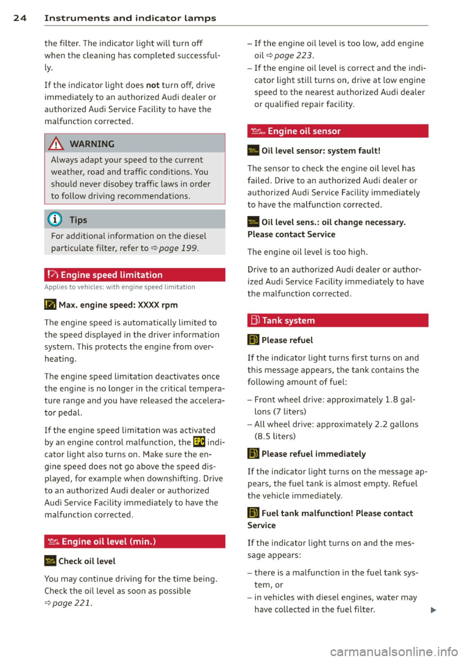
Bl Tank system
D Please refuel
If the indicator light turns first turns on and
t his message appears, the tan k contains the
following amount of fuel:
- Front wheel dr ive : approximately 1.8 gal
lons (7 liters)
- All wheel dr ive : approximately 2.2 gallons
(8 .5 liters)
II] Please refuel immediately
If the indicator light turns on the message ap
pears, the fuel tank is almost empty. Refuel
the vehicle immed iate ly.
D Fuel tank malfunction! Please contact
Service
If the indicator l ight turns on and the mes
sage appea rs:
- there is a malfunction in the fuel tank sys
tem, or
- in vehicles with diesel engines, water may
have collected in the fuel fi lter.
Page 29 of 310
....,
N
0 > co
rl I.O
"' ....,
"' rl
Driver information
system
Overview
Applies to vehicles: with dr iver information system
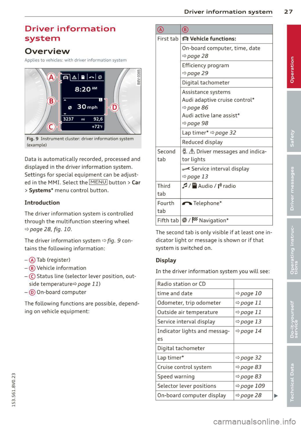
Fi g. 9 l nstrume nt cl uste r: dr ive r info rmatio n syste m
(ex am ple)
Data is automatica lly recorded , processed and
d isp layed in the dr iver information system .
Sett ings for special equ ipment can be adjust
ed in the MMI. Select the
! M ENU ! button> Car
> Systems * menu control button .
Introduction
The driver information system is controlled
through the mult ifunction steering wheel
c::;, page 28 , fig . 10 .
The driver information system c::;, fig. 9 con
tains the follow ing informat ion:
- @ Tab (register)
-@ Vehicle information
-© S ta tus line (se lecto r lever posi tion , ou t-
s ide temperature ¢page
11)
-@ O n-boa rd comp ute r
T he follow ing funct ions are possible , depend
i ng on vehicle equipment :
Driver in formation system 2 7
@ ®
First tab ~ Vehicle functions:
On-boa rd comp uter, time, date
¢ page28
Efficiency program
c=;, page29
Digita l tachometer
Assistance systems
Aud i adapt ive cruise control*
¢ page86
Aud i active lane ass ist*
¢ page 98
Lap timer* c::;, page 32
Reduced disp lay
Second
~ -Lh Driver messages and ind ica-
tab tor lights
~ Se
rv ice interval display
¢ page 13
Third fl I I Audio/ l'>l radio
tab
Fourth
r,. Telephone*
t ab
Fi fth tab
~I~ Naviga tion *
T he second tab is only v isib le if at least one in
dicator light or mess age is shown or if that
system is switched on.
Display
In the drive r information system you will see:
Rad io stat io n or CD
time and date
c:!;> page 10
Odometer, trip odometer c:!;> page 11
Outside air temperature c::;, page 11
Serv ice interva l disp lay ¢ page 13
Indicator lights and messag-<:!.> page 14
es
Dig ita l tachometer
L ap timer*
c:!;> page 32
Cruise control system ¢page 83
Speed war ning c:!;> page 83
Selec tor lever pos itions ¢page 109
On-bo ard comp uter display c:!;> page 2 8
Page 30 of 310
28 Driver information system
On-board computer display
The on-boa rd compute r display monitors the
different memory levels:
- Sho rt-term memo ry (on-board computer 1)
- Long-term memory (on-board computer
2)
-Efficiency program
The fo llow ing information can be displayed in
on-boa rd computer
1 and 2 one after the oth
er.
- Date
- Estimated range based on current fuel leve l
- T rave l time
- Average consumption
- Average speed
- Distance
- Current fuel consumption
- Engine oil temperature indicator*
On-board computer D (short-term
memory)
The sho rt-term memory co llects driving infor
mation from the time the ignit ion is switched
on until it is switched off. If you continue dr iv
ing
within two hours after switching the igni
tion off, the new values are included when cal
culating the current trip information. If stop ped for more the two hours, the short term
memory is automatically erased once you be
g in driving .
On-board computer fJ (long-term
memory)
Unlike the short-term memory, the long-term
memory is not erased automatically. You can
select the time period for evaluating trip in
formation yourself.
Efficiency program~
The efficiency program can help you to use
less fuel ~
page 29 .
(D Tips
-The on-board computer is controlled by
the left button f ields on the mult ifunc
t ion steering wheel. -
For information on using the other but
ton f ields, such as the audio, telephone*
and navigation* funct ions, see the MMI
owner's manual.
Operation
Appl ies to vehicles: wit h driver informatio n system
The driver information system is con trolled
with the multifunction steering wheel .
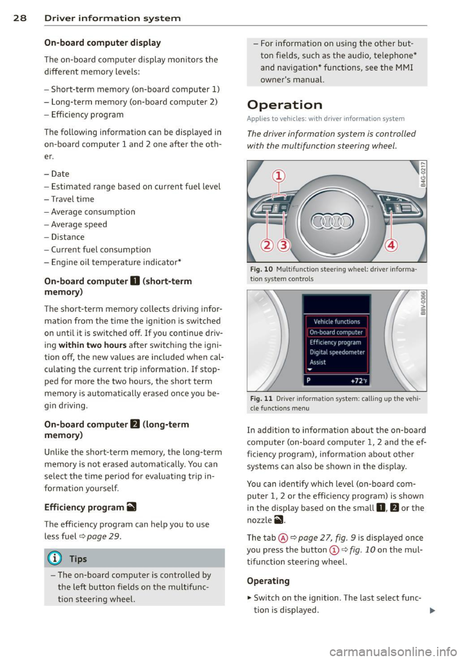
Fig. 10 Multi funct ion s teer ing w heel : driver informa ·
tio n syste m controls
Fig. 11 D river informa tion syste m: call ing up t he ve hi
cle func tion s men u
In add ition to info rmation about the on-board
computer (on-board computer 1 , 2 and the ef
ficiency program), information about other
systems can also be shown in the display .
You can identify which level (on-board com
puter 1, 2 or the efficiency program) is shown
in the d isp lay based on the small
0, fJ or the
nozzle
ii .
The tab@~ page 2 7, fig. 9 is displayed once
you press the button
(D ~ fig. 10 on the mul
tifunction steering wheel.
Operating
.,. Switch on the ignition . T he last select func-
tion is displayed . ..,_