AUDI S3 SEDAN 2017 Owners Manual
Manufacturer: AUDI, Model Year: 2017, Model line: S3 SEDAN, Model: AUDI S3 SEDAN 2017Pages: 400, PDF Size: 67.32 MB
Page 361 of 400
car to keep your balance and take care not
to slip .
Raising the vehicle
The vehicle must be li~ed with the jack first be
fore the wheel con be removed .
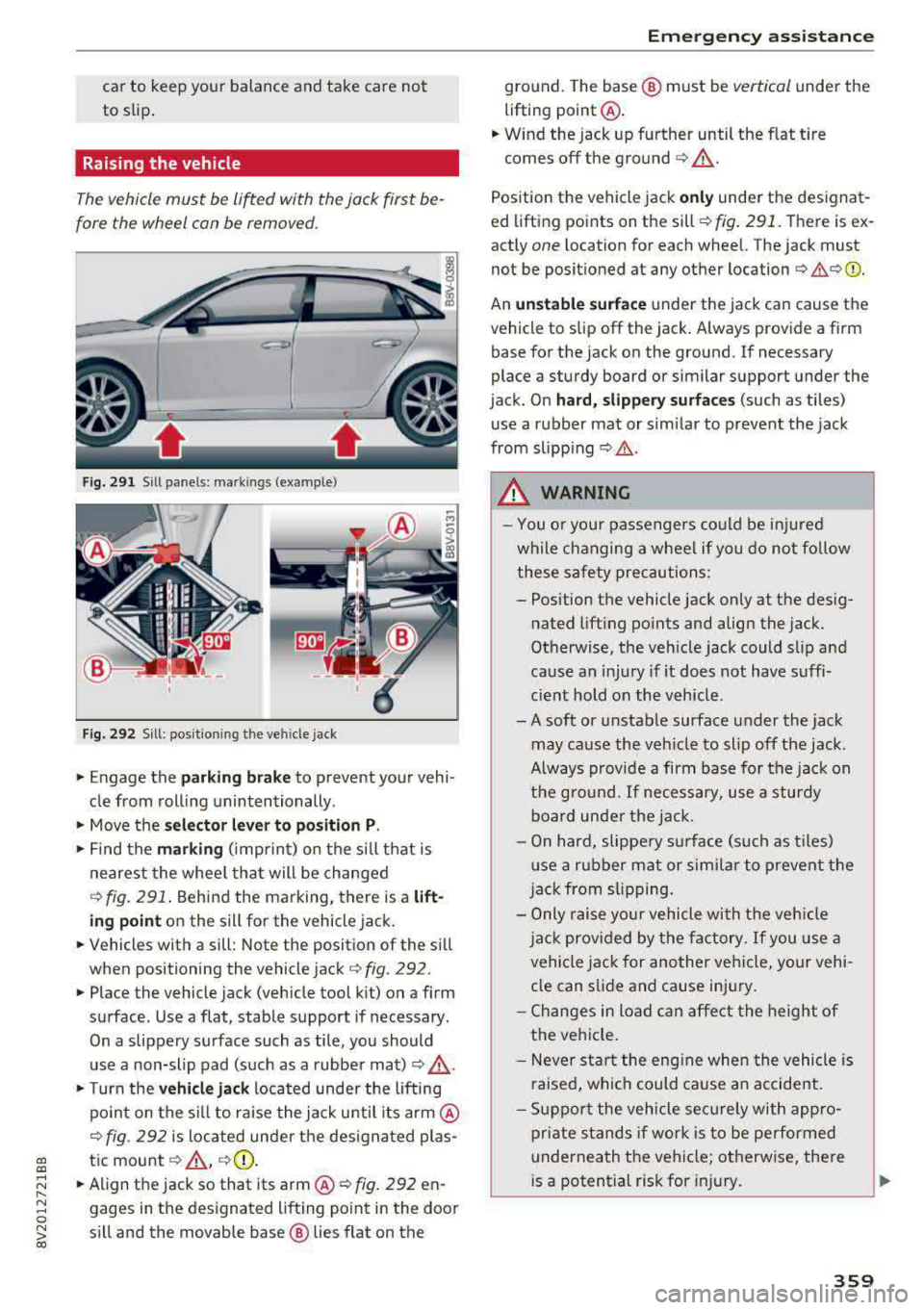
Fig. 291 S ill pane ls: mark ings (example)
F ig. 292 S ill: position ing the ve hicle jack
"Engage the parkin g brak e to prevent your vehi
cle from roll ing unintentionally .
"Move the se lector le ver to p osition P .
"Find the markin g (imprint) on the s ill that is
nearest the whee l tha t will be changed
r::> fig. 291 . Behind the marking, there is a lift
ing point on the sill for the vehicle jack.
"Vehicles with a sill: Note the position of the sill
when positioning the vehicle jack¢
fig. 292.
"Place the vehicle jack (vehicle tool kit) on a firm
surface. Use a flat, stable support if necessary.
On a slippery surface such as tile, you should
use a non-slip pad (such as a rubber mat) ¢
,&.
"Turn the ve hi cle jack located under the lifting
po int on the s ill to ra ise the jack until its
arm @
r::> fig. 292 is located under the des ignated plas-
gi tic mount r::> ,& , ¢0).
~ "Align the jack so that its arm @¢ fig. 292 en-
8 gages in the designated lift ing point in the door
~ sill and the movable base ® lies flat on the
Em ergen cy a ssis tanc e
ground. The base ® must be vertical unde r the
lifting point @.
"Wind the jack up further until the f lat tire
comes off the
ground ¢,& .
Position the vehicle jack only unde r the designat
ed lifting points on the sill¢
fig. 291. T here is ex
actly
one location for each wheel. The jack must
not be positioned at any other
location¢ ,&.¢0) .
An un sta b le surf ace under the jack can cause the
vehicle to slip off the jack . Always provide a firm
base for the jack on the ground. If necessary
place a sturdy board or similar support under the
jack. On
ha rd , s lippery surfa ces (such as tiles)
use a rubber mat or similar to prevent the jack
from
slipp ing ¢,&. .
.&, WARNING
-
-You o r you r passengers could be inj ured
while changing a wheel if you do not fo llow
these sa fety precautions :
- Position the vehicle jack only at the desig
nated lifting points and align the jack.
Otherwise, the vehicle jack could slip and
cause an injury if it does not have suffi
c ient hold on the vehicle .
-A soft or unstable surface under the jack may cause the veh icle to slip off the jack.
Always provide a firm base for the jack on
the g ro u nd. If necessary, use a sturdy
board unde r the jack.
- On hard, slippe ry su rface (s uch as t iles)
u se a r ubber mat or simi lar to prevent the
j ac k from slipping.
- Only raise yo ur vehicle with the veh icle
j ac k prov ided by the factory.
If you use a
vehicle jack for another veh icle, your vehi
cle can s lide and cause injury.
- Changes in load can affe ct the height of
the vehicle.
- Never star t the eng ine when the vehicle is
raised, which could cause an accident.
- Suppor t the vehicle se cur ely with appro
priate stands if work is to be performed
underneath the vehicle; otherwise, there
i s a potential risk for injury.
.,.
359
Page 362 of 400
Emerg ency assis ta nce
-To help prevent injury to yourself and your
passengers:
-Do not ra ise the vehicle until you are sure
the jack is secure ly engaged.
-Passengers must not remain in the vehicle
when it is jacked up.
-Make sure that passengers wait in a safe
place away from the vehicle and well away
from the road and traffic.
-Make sure jack posit ion is correct, adjust
as necessary and then cont inue to raise
the jack.
CD Note
Do not lift the vehicle by the sill. Position the
veh icle jack only at the designated lifting
points on the sill. Otherwise, your vehicle will
be damaged.
Taking the wheel off /installing the spare
Follow these instructions step-by-step for chang
ing the wheel .
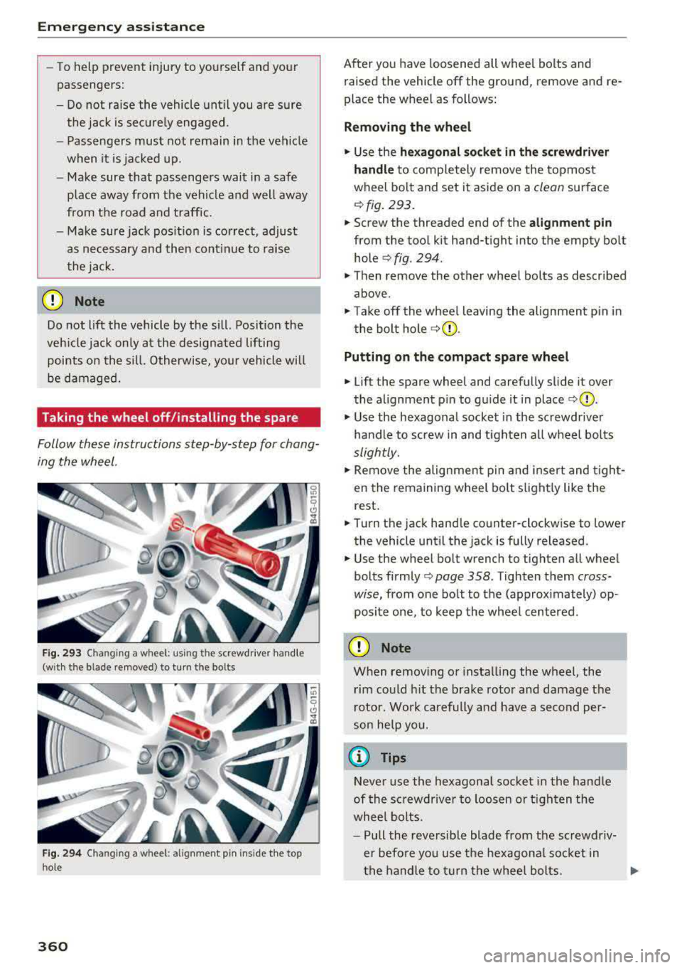
Fig . 293 Changing a wheel: using the screwdr iver hand le
(with the blade removed) to turn the bolts
Fig. 29 4 Changing a wheel: alignm ent pin ins ide the top
ho le
360
After you have loosened all wheel bolts and
raised the vehicle off the ground, remove and re
place the wheel as follows:
Removing the wheel
.. Use the he xago nal socket in th e screwdriver
handle
to comp letely remove the topmost
wheel bo lt and set it aside on a
clean surface
<=> fig. 293.
.. Screw the threaded end of the alig nm ent pi n
from the tool kit hand-tight into the empty bolt
hole
<=> fig. 294.
.. Then remove the other wheel bolts as described
above .
.. Take off the whee l leaving the alignment p in in
the bolt hole
<=> (j) .
Putting on the c omp act spare wheel
.. Lift the spare wheel and carefully slide it over
the alignment p in to gu ide it in place
<=>(j) .
.. Use the hexagonal socket in the screwdr iver
handle to screw in and t igh ten all wheel bolts
slightly.
.. Remove the alignmen t pin and insert and t igh t
en the remaining wheel bolt s light ly like the
rest .
.. Turn the jack hand le counter-clockwise to lower
the vehicle until the jack is fully released .
.. Use the wheel bolt wrench to tighten all wheel
bolts
firmly <=> page 358. Tighten them cross
wise,
from one bolt to the (approximately) op
posite one, to keep the wheel centered.
CD Note
When removing o r insta lling the wheel, the
rim could h it the brake rotor and damage the
r otor. Wor k carefully and have a second per
son he lp yo u.
{!) Tips
Neve r use the hexagonal socket in the handle
of th e sc rewdriver to loos en o r tigh ten the
whee l bolts.
-Pull the reve rsible blade from the screwdr iv
er befo re you use the hexagona l socket in
the handle to turn the whee l bolts.
Page 363 of 400
CXl CXl .... N ,.__
N .... 0 N > 00
-When mountin g tires w ith unidirectional
tread design
ma ke sure the t read pattern is
p oin ted the r ight way ¢
page 36 1.
-The wheel bolts should be clean and easy to
turn. C heck for d irt a nd cor rosion on the
ma ting surfaces o f both the wheel an d the
hub. Remove all dirt from t hese surfaces be
fo re remo unt ing the wheel.
Tires with unidirectional tread design
Tires with unidirectional tread design must be
mounted with their tread pattern pointed in the
right direction.
Using a spare t ire with a tread pattern
intended for use in a specific direction
W hen using a spa re t ire with a tread patte rn in
tended fo r use in a specific direction, please note
the following:
-The direct ion of rotat ion is ma rked by an a rrow
on the side of the tire .
-If the spare tire has to be installed in the incor
rect d irection, use the spare tire only tempora
ri ly s ince the tire w ill not be ab le to achieve its
opt imum p erformance c harac ter istics wi th re
gard to aquaplaning, noise and wea r.
-We recommend t hat you pay particular atten
t io n t o this fac t during we t weat her and that
yo u adju st yo ur speed to match road condi
ti ons.
-Rep lace the flat t ire with a new one and have it
insta lled on yo ur ve hicl e as soon as possibl e to
r es to re th e hand li n g adva ntages of a unid irec
tional t ire.
Notes on changing tires
Please read the info rmation I:!> page 3 35 if you
are go ing to use a spare tire which is different
from the tires on your veh icle.
Af te r yo u c hange a tire:
-Check the tire pressure on the spare immedi
ately after in stallation .
-Have the wheel bolt tightening torque
checked with a torque wrench as soon as pos -
Emergency assistance
sible by your authorized Audi dealer or a
qualified service station.
-With steel and alloy wheel rims, the wheel bolts are correctly tightened at a torque of
90 ft lb (120 Nm).
-If you notice that the wheel bolts are corroded
and difficult to turn while changing a tire ,
they should be replaced before you check the
tightening torque.
-Replace the flat tire with a new one and have
it installed on your vehicle as soon as possi ·
ble. Remount the wheel cover .
Until then , dr ive with extra care and at reduced
speeds.
_& WARNING
-I f you are going to equip yo ur vehicle with
tires or r ims which differ from those w hich
were factory installed, the n be sure to read
th e information
¢ pag e 335.
-Always make sure the damaged wheel or
e ven a flat tire a nd the jack and tool kit are
p rop erly secur ed in t he lu ggag e compart
m en t an d are not l oose in th e p asseng er
compa rtme nt.
-In an accide nt or sudde n man euv er th ey
could fly forward, injuri ng a nyo ne in the ve
hicl e.
-Always s tor e damag ed w heel, jack and t ools
securely i n the lu ggage compa rtm ent. Ot h
erwise, in an accid ent or sud den m aneuve r
t he y c ould fl y forwar d, ca using injury to pas
sen gers in the ve hicle.
-
361
Page 364 of 400
Emergency assistance
Spare tire
General information
Applies to: vehicles with space-saving spare tire (compact
spare tire)
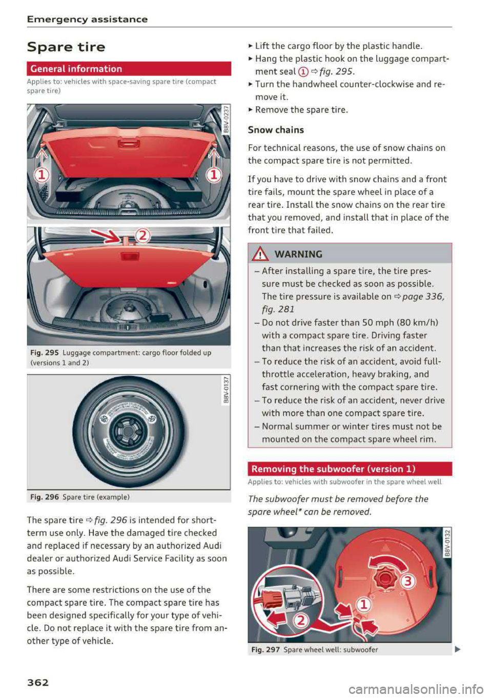
Fig. 295 L uggage compartment: cargo floor folded up
(versions 1 and 2)
Fig. 296 Spare tire (example)
The spare tire ~ fig. 296 is intended for short
term use only. Have the damaged tire checked
and replaced if necessary by an authorized Audi
dealer or authorized Audi Service Facility as soon
as possible.
There are some restrictions on the use of the
compact spare tire . The compact spare tire has
been designed specifically for your type of vehi
cle. Do not replace it with the spare tire from an
other type of vehicle.
362
.,. Lift the cargo floor by the plastic handle .
.,. Hang the p lastic hook on the luggage compart
ment
sea l© ~ fig. 295.
.,. Turn the handwheel counter-clockwise and re-
move it .
.,. Remove the spare tire.
Snow chains
For technical reasons, the use of snow chains on
the compact spare tire is not permitted .
If you have to drive with snow chains and a front
tire fails, mount the spare wheel in p lace of a
rear tire. Install the snow chains on the rear tire
that you removed, and install that in place of the
front tire that failed.
A WARNING
-
-After installing a spare tire, the tire pres
sure must be checked as soon as possible.
The tire pressure is available on
~ page 336,
fig.
281
- Do not dr ive faster than SO mph (80 km/h)
w ith a compact spare tire. Driving faster
than that increases the risk of an accident.
- To reduce the r isk of an accident, avoid full
throttle acceleration, heavy braking, and
fast cornering with the compact spare tire.
- To reduce the r isk of an accident, never drive
w ith more than one compact spare tire.
- Normal summer or w inter t ires must not be
mounted on the compact spare wheel rim.
Removing the subwoofer (version 1)
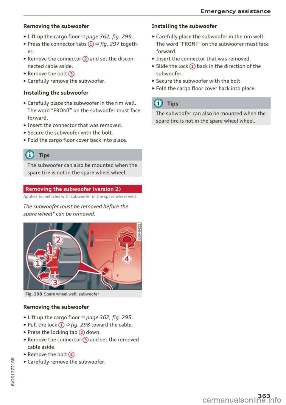
Applies to: vehicles with subwoofer in the spare whee l well
The subwoofer must be removed before the
spare wheel* can be removed.
Fig. 297 Spare whee l we ll: subwoofer
Page 365 of 400
a, a, ..... N
" N ..... 0 N > 00
Removing the subwoofer
• Lift up the cargo floor ¢ page 362, fig. 295.
• Press the connector tabs CD¢ fig. 297 togeth
er.
• Remove the connector @and set the discon-
nected cab le aside.
• Remove the bolt@.
• Carefully remove the subwoofer .
Installing the subwoofer
• Carefully place the subwoofer in the rim wel l.
The word "FRONT" on the subwoofer must face
forward.
• Insert the connector that was removed .
• Secure the subwoofer with the bolt.
• Fold the cargo floor cover back into place .
@ Tips
The subwoofer can also be mounted when the
spare tire is not in the spare wheel wheel.
Removing the subwoofer (version 2)
App lies to: vehicles with subwoofer in the spare wheel well
The subwoofer must be removed before the
spore wheel* can be removed .
Fig. 298 Spare w heel well : su bwoofer
Removing the subwoofer
• Lift up the cargo floor ¢ page 362, fig . 295.
• Pull the lock CD¢ fig. 298 toward the cable.
• Press the locking tab@down.
• Remove the connector @ and set the removed
cable aside .
"' Remove the bolt@.
• Caref ully remove the subwoofer.
Emergency assistance
Installing the subwoofer
• Carefully place the subwoofer in the rim well.
The word "FRON T" on the subwoofer must face
forward.
• Insert the connector that was removed .
• Slide the lock CD back in the direction of the
subwoofer .
• Secure the subwoo fer with the bolt.
"' Fold the cargo floor cover back into place .
@ Tips
The subwoofer can also be mounted when the
spare tire is not in the spare wheel wheel.
363
Page 366 of 400
Fuses and bulbs
Fuses and bulbs
Fuses
Changing fuses
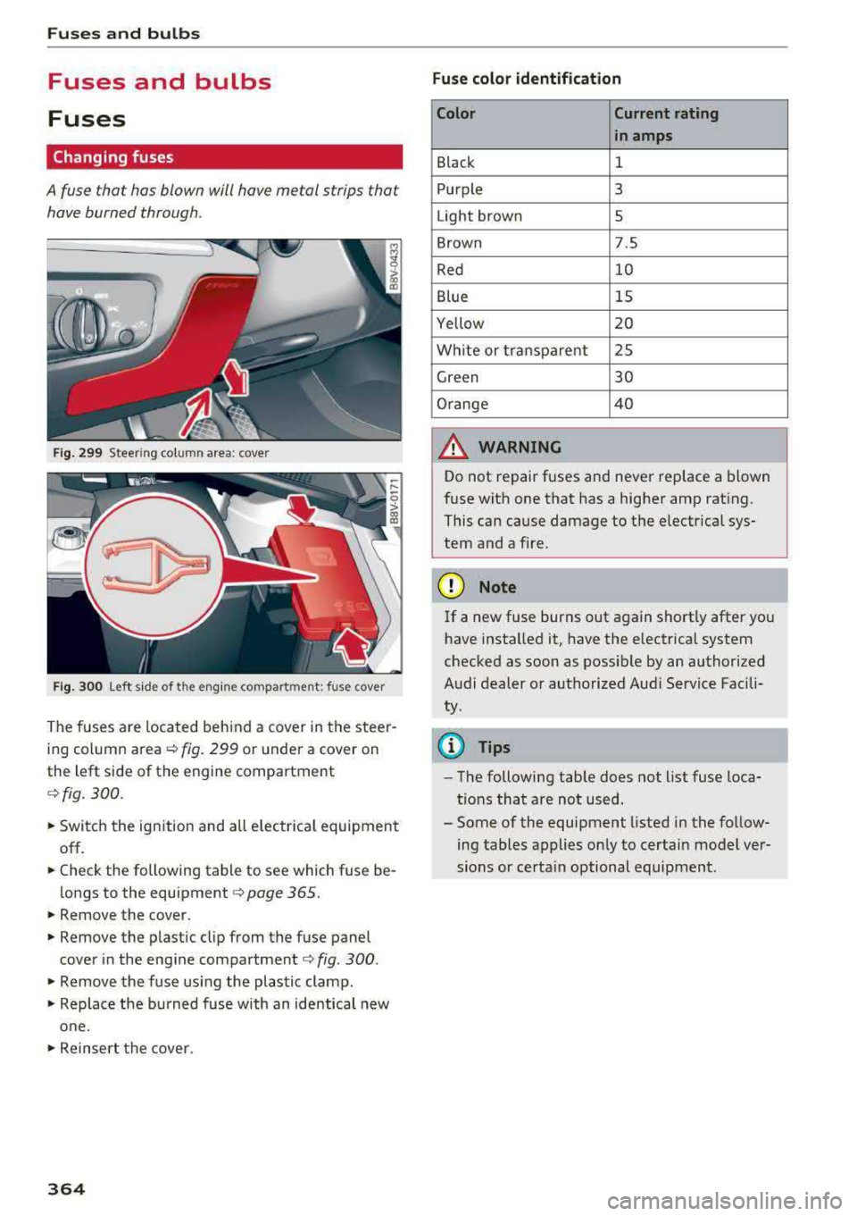
A fuse that has blown will have me tal strips that
have burned through .
Fig. 2 99 Stee rin g co lu m n a rea : cove r
Fig. 30 0 Left s ide of the engine co mpart ment: fuse cover
The fuses are located behind a cover in the steer
i n g column
area ¢ fig. 299 or under a cover on
the left side of the engine compartment
¢ fig. 300 .
• Switc h the ignition and all e lectr ica l equipment
off.
• Check the following table to see which fuse be
longs to the
equipment ¢ page 365.
• Remove the cover.
• Remove the plastic cl ip from the fuse panel
cove r in the eng ine
compartment ¢ fig. 300 .
• Remove the fuse us ing the plastic clamp.
• Replace the bu rned fuse w ith an identical new
o ne.
• Reinser t the cover.
364
Fuse color identification
Color Current rating
in amps
Black 1
Purple 3
Light brown 5
Brown 7.5
Red 10
Blue 15
Yellow 20
Wh ite or transpa re nt 25
Green 30
Orange 4 0
A WARNING
-
Do not repair fuses and never replace a blown
f u se with one that has a higher amp rat ing.
This can cause damage to the e lectr ica l sys
tem and a fire.
(D Note
If a new fuse burns out again sho rtly after you
h ave installed it, have the electrical system
checked as soon as possible by an authorized
A udi dealer or authorized Aud i Service Fac ili
ty .
(D Tips
-The following table does not list fuse loca
t ions that are not used.
- Some of the equipment listed in the fo llow
ing tables applies on ly to certai n model ver
sions or certa in optional equipment .
Page 367 of 400
a, co ..... N
" N ..... 0 N > 00
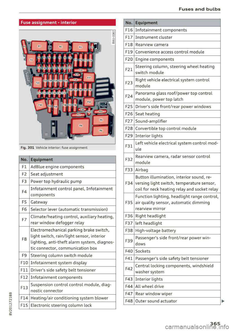
Fuse assignment -interior
Fig. 301 Vehicle interior: fuse assignment
No. Equipment
Fl Ad
Blue engine components
F2 Seat adjustment
F3 Power top hyd
raulic pump
F4 Infotainment control panel, Infotainment
components
FS Gateway
F6 Selector lever (automat ic transmission)
F7 Climate/heating control, auxiliary heating,
rear window defogger relay
Electromechan ica l parking brake sw itch,
F8 light switch,
rain/light sensor, inte rior
lighting, anti-theft alarm system, diagnos -
tic connector, communication box
F9 Steering column sw itch module
Fl0 Infotainment system display
Fll Dr iver's side safety belt tens ioner
F12 Infotainment components
F13 Suspension
control control module, diag-
nostic connector
F14 Heating/air conditioning system blower
FlS Electronic steering column lock
No .
Fl6
F 17
Fl8
F 19
F20
F21
F2 3
F24
F 2S
F26
F 27
F28
F2 9
F 31
F32
F33
F34
F 3S
F36
F3 7
F38
F39
F 40
F41
F42
F43
F44
F47
F4 8
Fuses and bulbs
Equipment
Infotainment components
Instrument cluster
Rearview camera
Convenience access cont rol module
Engine components
Steering column, steering wheel heating
switch module
Right vehicle electrical system control
module
Panorama glass roof/power top control
module, power top latch
Driver's s ide front/rear power w indows
Seat heating
Sound-amplifier
Convertible top control module
Interior lights
Left vehicle electrical system control mod-
ule
Rearview camera, radar sensor control
module
A irbag
Button i llumination, interior sound, re-
versing light switch, temperature sensor,
coil for neck heating relay and socket relay
Fu nct ion lighting, headl ight range control,
a ir quality sensor, automatic dimming
rearview mirror
R ight headlight
l eft headlight
High-voltage battery
Passenger's s ide front/rear power win -
dows
Sockets Passenger's side safety belt tensioner
Cen tral locking components, windshield
washer system
Interior lights
Al l wheel drive
Rear w indow wiper
Outer sound actuator
365
Page 368 of 400
Fuses and bulbs
No . Equipment
F49 Starter, clutch sensor, high-voltage bat-
tery, power electronics
FS3 Rear window defogger
The power seats* are protected via
circuit break
ers
that automatically switch on after a few sec
onds after the overload has been reduced.
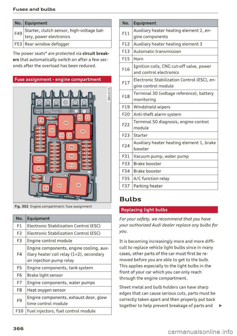
Fuse assignment - engine compartment
F ig . 302 Engine co mpa rtment: fuse assignmen t
No. Equipment
Fl E
lectronic Stabilization Control (ESC)
F2 Electronic Stabilization Control ( ESC)
F3 Engine control module
Engine components, eng ine cooling, aux-
F4 ilia
ry heater coil relay (1+2), secondary
air injection pump relay
FS Engine components, tank system
F6 Brake light sensor
F7 Engine components, water pumps
FB Heat oxygen sensor
F9 Engine components, exhaust door, glow
time control module
FlO Fue l injectors, fuel control module
366
No . Equipment
Fll Auxiliary heater heating element 2
, en-
gine components
F l2 Auxiliary heater heating element 3
Fl3 Automatic transmission
F lS Horn
F l6 Ignition coils, CNG cut-off valve, power
and control electronics
Fl7 Elec
tronic Stabilization Control (ESC), en -
gine contro l module
Fl8 Terminal 30 (voltage
reference), battery
monitoring
F19 Windshield wipers
F20 Anti-theft alarm system
F 22 Terminal SO diagnosis, engine control
module
F2 3 Starter
F 24 Auxiliary heater heating element 1, brake
booster
F31 Vacuum pump, water pump
F33 Brake booster
F34 Brake booster
F35 A/C function relay
F37 Parking heater
Bulbs
Replacing light bulbs
For your safety, we recommend that you have
your authorized Audi dealer replace any bulbs for you.
It is becoming increasingly more and more diffi
cu lt to replace vehicle light bulbs since in many
cases, other parts of the car must first be re
moved before you are able to get to the bulb.
This applies especially to the light bulbs in the
front of your car which you can only reach
through the engine compartment.
Sheet meta l and bulb holders can have sharp
edges that can cause serious cuts, parts must be
correctly taken apa rt and then properly put back
together to help prevent breakage of parts and
..,.
Page 369 of 400
CXl CXl .... N ,.__
N .... 0 N > 00
long term damage from water that can enter
housings that have not been properly resea led.
F or your safety, we recommend that you have
your author ized Audi dealer replace any b ulbs for
you, since your dealer has the proper tools, the
correct bulbs and the expertise.
Ga s di sc har ge l amp s (Xe non light s)
Due to the high electrical voltage, have the bulbs
replaced by a qua lified technician . Headlights
with Xenon light are identified by the high-volt
age sticker.
LE D hea dlight s*
LED headlights require no maintenance. Please
contact your authorized Audi dealer if a bulb needs to be replaced .
A WARNING
Changing Xenon lamps w ithout the necessa ry
equipment can cause ser ious personal injury .
- Bulbs are pressur ized and can explode when
being changed . Potential risk of injury!
- On vehicles
equipped with gas discharge
bulbs (Xenon l ight) life-threatening injuries
can result from improper handling of the
high-voltage po rtions of such lamps!
- Only you r authorized Aud i dea ler or quali
fied workshop should change the bulbs in
gas dis charge lamps. There are parts with
sharp edges on the openings and on the
bulb ho lders that can cause serious cuts . If
you are uncertain about what to do, have
the work perfo rmed by an authorized Audi
dealer or qualif ied workshop. Serious per
sonal injury may resu lt from improperly per
formed work.
@ Tips
- If you still prefer to rep lace the light bu lbs
yourself, be aware that the engine compart
ment is a hazardous area to work
in¢ .&. in
Working in the engine compartment on
page 316 .
-It is best to ask your authorized Audi dealer
whenever you want to change a bulb .
Fuses an d bulb s
367
Page 370 of 400
Emergency situations
Emergency situations
General
Thi s chapter is intended for trained eme rgency
crews and working per sonnel who have the nec
essary tool s and equipment to perform these
ope rations.
Starting by pushing or
towing
(D Note
Vehicles wi th an au tomat ic tra nsmission can
not be starte d by pushi ng or towi ng.
Starting with jumper
cables
If necessary, the engine con be started by con
necting it to the battery of another vehicle .
Plug -In hybrid drive* : The con nection poin ts for
the jump start cables vary ¢
page 104.
If t he engine sho uld fa il to s tart because of a dis
c har ged o r we ak battery, the batt ery c an be con
nected to the ba ttery of
another vehicle, using a
pair of jumper cable s to start the engine .
Jumper cables
Use only jumper cables of suffi cien tly large cross
se ction
to car ry the s tarter cur rent safely. Refer
t o the man ufact urer 's spe cifica tions.
Use o nly jumper cables with
insulated te rm inal
clamps whi ch a re distin ct ly ma rked :
positive (+ ) cable , in most cases colored red
negative(-) cable ,
in most cases colo red black.
A WARNING
Plug-in hybr id d rive*: you must not give a
jump start with your vehicle. This could cause sign ifica nt damage to the electrical system in
your vehicle
¢ pag e 104.
368
A WARNING ,_ -
Batteries conta in e lectr ic ity, acid, and gas.
A ny of these ca n cause very ser ious or fatal in
ju ry . Follow the ins truct io ns be low for safe
h andling of you r ve hicle's bat tery.
- Always sh ie ld your eyes and avo id leaning
over the battery w henever p ossible .
- A dead battery can freeze at temperatures
around 32 °F (0 °C) .
If the vehicle batte ry is
fro zen, yo u m ust t haw i t befo re connect ing
t he jump s tart cables. If y ou do no t, t his in
creases the r isk of an explos io n and chemi
c a l bur ns. A fter jump st art in g the vehicle,
drive to an aut ho riz e d Au di dea ler o r auth o r
ized Au di Service Faci lity immediately to
have the vehicle batte ry c hecked.
- Do not allow battery ac id to contact eyes or
skin. Fl ush any contacte d area with water
immed iate ly.
- Improper use of a booste r batte ry to sta rt a
veh icle may cause an exp losion.
- Veh icle batteries gene rate exp losive gases.
K eep s parks, flame an d lig hte d ciga rettes
away from batter ies .
- Do not t ry to jump start any vehicle with a
low acid level in the batte ry .
- The vo ltage of the booster batte ry must a lso
have a 12-volt rat ing. The capacity (Ah) of
the booster battery should not be lower
than that of the discharged battery. Use of
batter ies of diffe re nt voltage or substantial
ly diffe rent
"A h" rating may cause an exp lo
sion and perso na l inju ry .
- Never cha rge a frozen battery. Gas trapped
in the ice may cause an ex plosion .
- Never cha rge o r use a battery that has been
frozen . The battery case may have be w eak
e ned.
- Use of batter ies of different voltage or sub
s tan tially d if f eren t capacity (Ah) ra t ing may
cause an exp losion and injury. T he capac ity
(Ah) of the booste r ba ttery sho uld not be
l o wer th an that of the dis ch arged battery .
- B efore you c heck anyth ing in the eng ine
co mpart me nt, alw ays re ad and h eed all
W AR NING S
¢page 316.