Crankshaft AUDI S4 1998 B5 / 1.G Engine Manual
[x] Cancel search | Manufacturer: AUDI, Model Year: 1998, Model line: S4, Model: AUDI S4 1998 B5 / 1.GPages: 72, PDF Size: 3.25 MB
Page 3 of 72
3
This Self-study Programme provides you with information
regarding design and function.
The Self-study Programme is not a Workshop Manual!
Please refer to the Service Literature for all the relevant
maintenance and repair instructions.
Page
Engine .........................................................
Technical data, crankshaft, cylinder head,
camshaft timing, cooling circuit, engine
lubrication, overview of components, air ducting,
charging, exhaust system, pneumatically
controlled systems, charge pressure control, air
divert control in overrun, ACF system, crankcase
breather
4
Motronic ME 7.1 ..........................................
Subfunctions, system overview
31
Subsystems of the Motronic .....................
Torque-oriented engine management, torque-
oriented functional structure, Electronic throttle,
exhaust gas temperature control
33
Sensors .......................................................
Additional sensors of the Motronic
49
Auxiliary signals/interfaces ...................... 57
Functional diagram ..................................... 62
Self-diagnosis .............................................
Vehicle diagnosis, test and information system
VAS 5051, test box V.A.G 1598/31
64
Transmission ..............................................
Self-adjusting clutch, gearbox
66
Contents
Important!/Note!
New!
Page 6 of 72
6
Engine
The crankshaft
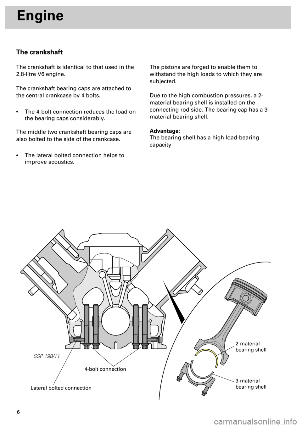
The crankshaft is identical to that used in the
2.8-litre V6 engine.
The crankshaft bearing caps are attached to
the central crankcase by 4 bolts.
•
The 4-bolt connection reduces the load on
the bearing caps considerably.
The middle two crankshaft bearing caps are
also bolted to the side of the crankcase.
•
The lateral bolted connection helps to
improve acoustics.The pistons are forged to enable them to
withstand the high loads to which they are
subjected.
Due to the high combustion pressures, a 2-
material bearing shell is installed on the
connecting rod side. The bearing cap has a 3-
material bearing shell.
Advantage:
The bearing shell has a high load-bearing
capacity
SSP 198/11
Lateral bolted connection
4-bolt connection
2-material
bearing shell
3-material
bearing shell
Page 14 of 72
1415
SSP 198/49
Engine
Engine lubrication
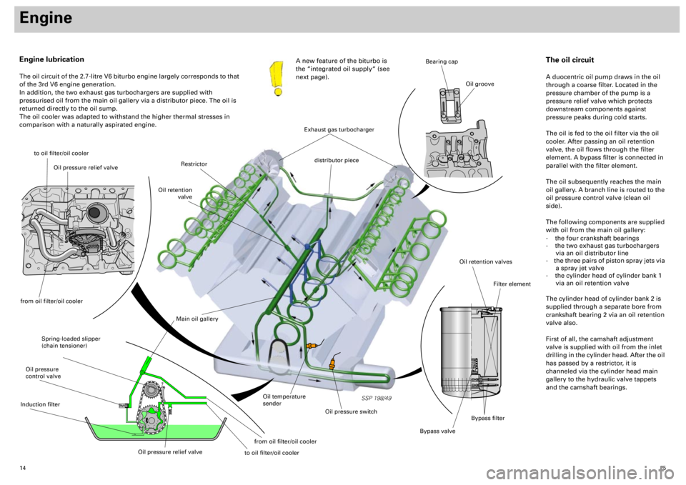
The oil circuit of the 2.7-litre V6 biturbo engine largely corresponds to that
of the 3rd V6 engine generation.
In addition, the two exhaust gas turbochargers are supplied with
pressurised oil from the main oil gallery via a distributor piece. The oil is
returned directly to the oil sump.
The oil cooler was adapted to withstand the higher thermal stresses in
comparison with a naturally aspirated engine.A new feature of the biturbo is
the “integrated oil supply“ (see
next page).
to oil filter/oil cooler
Spring-loaded slipper
(chain tensioner)
Main oil gallery
Oil retention valves
Bypass valve
Filter element
Bearing cap
Oil groove
Oil temperature
sender
Oil pressure switch
Restrictor
Oil retention
valve
distributor piece
The oil circuit
A duocentric oil pump draws in the oil
through a coarse filter. Located in the
pressure chamber of the pump is a
pressure relief valve which protects
downstream components against
pressure peaks during cold starts.
The oil is fed to the oil filter via the oil
cooler. After passing an oil retention
valve, the oil flows through the filter
element. A bypass filter is connected in
parallel with the filter element.
The oil subsequently reaches the main
oil gallery. A branch line is routed to the
oil pressure control valve (clean oil
side).
The following components are supplied
with oil from the main oil gallery:
- the four crankshaft bearings
- the two exhaust gas turbochargers
via an oil distributor line
- the three pairs of piston spray jets via
a spray jet valve
- the cylinder head of cylinder bank 1
via an oil retention valve
The cylinder head of cylinder bank 2 is
supplied through a separate bore from
crankshaft bearing 2 via an oil retention
valve also.
First of all, the camshaft adjustment
valve is supplied with oil from the inlet
drilling in the cylinder head. After the oil
has passed by a restrictor, it is
channeled via the cylinder head main
gallery to the hydraulic valve tappets
and the camshaft bearings.
Exhaust gas turbocharger
Bypass filter
Oil pressure relief valve
from oil filter/oil coolerOil pressure
control valveInduction filter
Oil pressure relief valve
from oil filter/oil cooler
to oil filter/oil cooler
Page 15 of 72
16
Engine
The component parts of the oil circuit
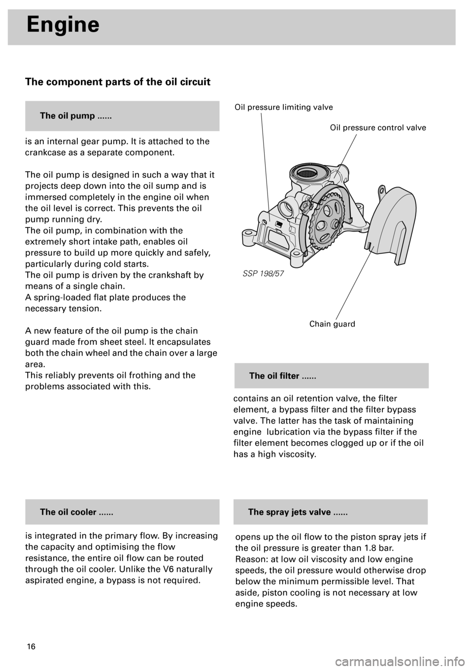
is integrated in the primary flow. By increasing
the capacity and optimising the flow
resistance, the entire oil flow can be routed
through the oil cooler. Unlike the V6 naturally
aspirated engine, a bypass is not required.
The oil cooler ......
contains an oil retention valve, the filter
element, a bypass filter and the filter bypass
valve. The latter has the task of maintaining
engine lubrication via the bypass filter if the
filter element becomes clogged up or if the oil
has a high viscosity.
The oil filter ......
opens up the oil flow to the piston spray jets if
the oil pressure is greater than 1.8 bar.
Reason: at low oil viscosity and low engine
speeds, the oil pressure would otherwise drop
below the minimum permissible level. That
aside, piston cooling is not necessary at low
engine speeds.
The spray jets valve ......
SSP 198/57
Oil pressure control valve
Oil pressure limiting valve
Chain guard
is an internal gear pump. It is attached to the
crankcase as a separate component.
The oil pump is designed in such a way that it
projects deep down into the oil sump and is
immersed completely in the engine oil when
the oil level is correct. This prevents the oil
pump running dry.
The oil pump, in combination with the
extremely short intake path, enables oil
pressure to build up more quickly and safely,
particularly during cold starts.
The oil pump is driven by the crankshaft by
means of a single chain.
A spring-loaded flat plate produces the
necessary tension.
A new feature of the oil pump is the chain
guard made from sheet steel. It encapsulates
both the chain wheel and the chain over a large
area.
This reliably prevents oil frothing and the
problems associated with this.
The oil pump ......
Page 33 of 72
34
Subsystems of the Motronic
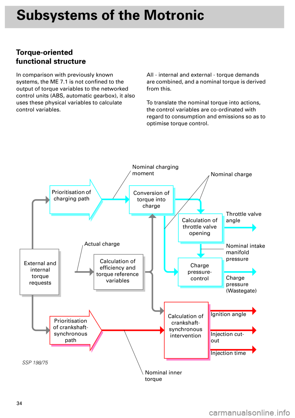
In comparison with previously known
systems, the ME 7.1 is not confined to the
output of torque variables to the networked
control units (ABS, automatic gearbox), it also
uses these physical variables to calculate
control variables.All - internal and external - torque demands
are combined, and a nominal torque is derived
from this.
To translate the nominal torque into actions,
the control variables are co-ordinated with
regard to consumption and emissions so as to
optimise torque control.
SSP 198/75
External and
internal
torque
requests
Calculation of
efficiency and
torque reference
variables
Prioritisation of
charging path
Prioritisation
of crankshaft-
synchronous
path
Conversion of
torque into
charge
Throttle valve
angle
Charge
pressure-
control
Calculation of
crankshaft-
synchronous
intervention
Calculation of
throttle valve
opening
Charge
pressure
(Wastegate)
Ignition angle
Injection cut-
out
Injection time
Nominal charging
moment
Nominal charge
Nominal intake
manifold
pressure
Nominal inner
torque
Actual charge
Torque-oriented
functional structure
Page 34 of 72
35
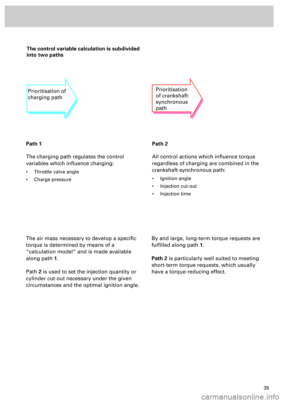
The control variable calculation is subdivided
into two paths
Path 1
The charging path regulates the control
variables which influence charging:
• Throttle valve angle
• Charge pressure
Path 2
All control actions which influence torque
regardless of charging are combined in the
crankshaft-synchronous path:
• Ignition angle
• Injection cut-out
• Injection time
The air mass necessary to develop a specific
torque is determined by means of a
“calculation model“ and is made available
along path
1
.
Path
2
is used to set the injection quantity or
cylinder cut-out necessary under the given
circumstances and the optimal ignition angle.
Prioritisation of
charging pathPrioritisation
of crankshaft-
synchronous
path
By and large, long-term torque requests are
fulfilled along path
1
.
Path 2
is particularly well suited to meeting
short-term torque requests, which usually
have a torque-reducing effect.
Page 53 of 72
54
Sensors
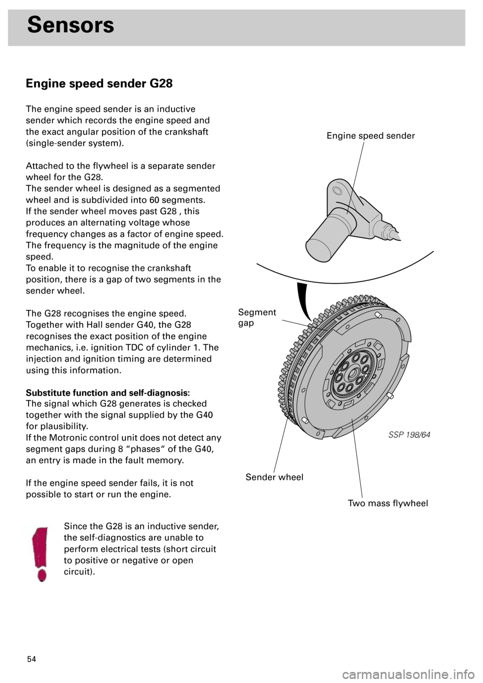
Engine speed sender G28
The engine speed sender is an inductive
sender which records the engine speed and
the exact angular position of the crankshaft
(single-sender system).
Attached to the flywheel is a separate sender
wheel for the G28.
The sender wheel is designed as a segmented
wheel and is subdivided into 60 segments.
If the sender wheel moves past G28 , this
produces an alternating voltage whose
frequency changes as a factor of engine speed.
The frequency is the magnitude of the engine
speed.
To enable it to recognise the crankshaft
position, there is a gap of two segments in the
sender wheel.
The G28 recognises the engine speed.
Together with Hall sender G40, the G28
recognises the exact position of the engine
mechanics, i.e. ignition TDC of cylinder 1. The
injection and ignition timing are determined
using this information.
Substitute function and self-diagnosis:
The signal which G28 generates is checked
together with the signal supplied by the G40
for plausibility.
If the Motronic control unit does not detect any
segment gaps during 8 “phases“ of the G40,
an entry is made in the fault memory.
If the engine speed sender fails, it is not
possible to start or run the engine.
Since the G28 is an inductive sender,
the self-diagnostics are unable to
perform electrical tests (short circuit
to positive or negative or open
circuit).
SSP 198/64
Two mass flywheel
Sender wheel
Engine speed sender
Segment
gap