Crankshaft sensor AUDI S4 1998 B5 / 1.G Engine Manual
[x] Cancel search | Manufacturer: AUDI, Model Year: 1998, Model line: S4, Model: AUDI S4 1998 B5 / 1.GPages: 72, PDF Size: 3.25 MB
Page 3 of 72

3
This Self-study Programme provides you with information
regarding design and function.
The Self-study Programme is not a Workshop Manual!
Please refer to the Service Literature for all the relevant
maintenance and repair instructions.
Page
Engine .........................................................
Technical data, crankshaft, cylinder head,
camshaft timing, cooling circuit, engine
lubrication, overview of components, air ducting,
charging, exhaust system, pneumatically
controlled systems, charge pressure control, air
divert control in overrun, ACF system, crankcase
breather
4
Motronic ME 7.1 ..........................................
Subfunctions, system overview
31
Subsystems of the Motronic .....................
Torque-oriented engine management, torque-
oriented functional structure, Electronic throttle,
exhaust gas temperature control
33
Sensors .......................................................
Additional sensors of the Motronic
49
Auxiliary signals/interfaces ...................... 57
Functional diagram ..................................... 62
Self-diagnosis .............................................
Vehicle diagnosis, test and information system
VAS 5051, test box V.A.G 1598/31
64
Transmission ..............................................
Self-adjusting clutch, gearbox
66
Contents
Important!/Note!
New!
Page 53 of 72

54
Sensors
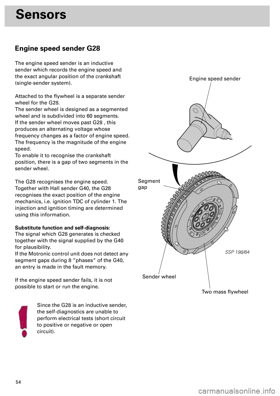
Engine speed sender G28
The engine speed sender is an inductive
sender which records the engine speed and
the exact angular position of the crankshaft
(single-sender system).
Attached to the flywheel is a separate sender
wheel for the G28.
The sender wheel is designed as a segmented
wheel and is subdivided into 60 segments.
If the sender wheel moves past G28 , this
produces an alternating voltage whose
frequency changes as a factor of engine speed.
The frequency is the magnitude of the engine
speed.
To enable it to recognise the crankshaft
position, there is a gap of two segments in the
sender wheel.
The G28 recognises the engine speed.
Together with Hall sender G40, the G28
recognises the exact position of the engine
mechanics, i.e. ignition TDC of cylinder 1. The
injection and ignition timing are determined
using this information.
Substitute function and self-diagnosis:
The signal which G28 generates is checked
together with the signal supplied by the G40
for plausibility.
If the Motronic control unit does not detect any
segment gaps during 8 “phases“ of the G40,
an entry is made in the fault memory.
If the engine speed sender fails, it is not
possible to start or run the engine.
Since the G28 is an inductive sender,
the self-diagnostics are unable to
perform electrical tests (short circuit
to positive or negative or open
circuit).
SSP 198/64
Two mass flywheel
Sender wheel
Engine speed sender
Segment
gap