Turbo AUDI S4 1998 B5 / 1.G Engine Manual
[x] Cancel search | Manufacturer: AUDI, Model Year: 1998, Model line: S4, Model: AUDI S4 1998 B5 / 1.GPages: 72, PDF Size: 3.25 MB
Page 1 of 72
Service.
For internal use only
198
All rights reserved. Subject
to change.
AUDI AG
Dept.I/GS-5
D-85045 Ingolstadt
Fax +49.841/89-6367
740.2810.17.20
Technical status: 01/98
Printed in Germany
The 2.7-litre V6 Biturbo
Design and Function
Self-study Programme 198
Page 2 of 72
2
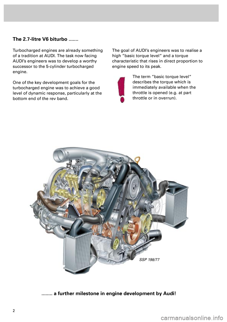
The 2.7-litre V6 biturbo .......
Turbocharged engines are already something
of a tradition at AUDI. The task now facing
AUDI’s engineers was to develop a worthy
successor to the 5-cylinder turbocharged
engine.
One of the key development goals for the
turbocharged engine was to achieve a good
level of dynamic response, particularly at the
bottom end of the rev band.
........ a further milestone in engine development by Audi!
The goal of AUDI’s engineers was to realise a
high “basic torque level“ and a torque
characteristic that rises in direct proportion to
engine speed to its peak.
The term “basic torque level“
describes the torque which is
immediately available when the
throttle is opened (e.g. at part
throttle or in overrun).
SSP 198/77
Page 4 of 72
4
Engine
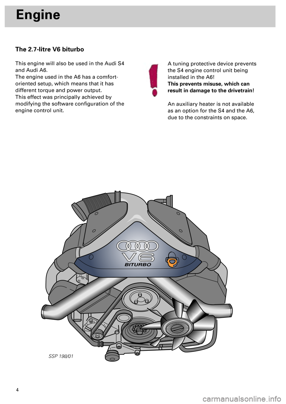
The 2.7-litre V6 biturbo
This engine will also be used in the Audi S4
and Audi A6.
The engine used in the A6 has a comfort-
oriented setup, which means that it has
different torque and power output.
This effect was principally achieved by
modifying the software configuration of the
engine control unit.A tuning protective device prevents
the S4 engine control unit being
installed in the A6!
This prevents misuse, which can
result in damage to the drivetrain!
An auxiliary heater is not available
as an option for the S4 and the A6,
due to the constraints on space.
BITURBO
SSP 198/01
Page 5 of 72
5
The technical data
•
Configuration:
V6 engine with 90° V-angle and twin
turbochargers
•
Engine code:
S4: AGB
A6: AJK
•
Output:
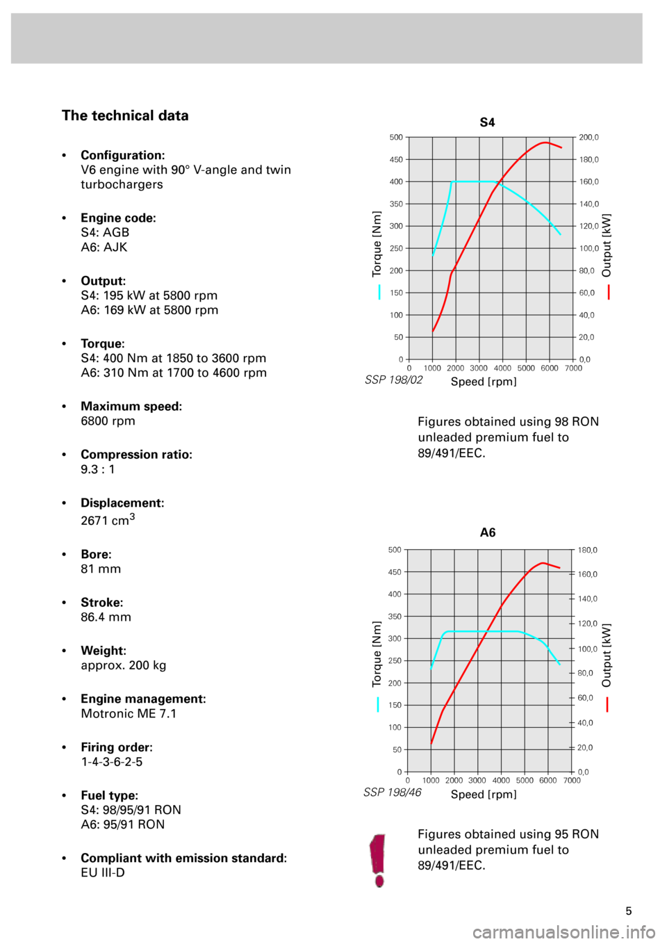
S4: 195 kW at 5800 rpm
A6: 169 kW at 5800 rpm
•
Torque:
S4: 400 Nm at 1850 to 3600 rpm
A6: 310 Nm at 1700 to 4600 rpm
•
Maximum speed:
6800 rpm
•
Compression ratio:
9.3 : 1
•
Displacement:
2671 cm
3
•
Bore:
81 mm
•
Stroke:
86.4 mm
•
Weight:
approx. 200 kg
•
Engine management:
Motronic ME 7.1
•
Firing order:
1-4-3-6-2-5
•
Fuel type:
S4: 98/95/91 RON
A6: 95/91 RON
•
Compliant with emission standard:
EU III-DFigures obtained using 98 RON
unleaded premium fuel to
89/491/EEC.
Figures obtained using 95 RON
unleaded premium fuel to
89/491/EEC.
500
450
400
350
300
250
200
150
100
50
0200,0
180,0
160,0
140,0
120,0
100,0
80,0
60,0
40,0
20,0
0,0
0 1000 2000 3000 4000 5000 6000 7000
SSP 198/02
Speed [rpm]
Torque [Nm]Output [kW]
S4
500
450
400
350
300
250
200
150
100
50
0180,0
160,0
140,0
120,0
100,0
80,0
60,0
40,0
20,0
0,0
0 1000 2000 3000 4000 5000 6000 7000
SSP 198/46
Speed [rpm]
Torque [Nm]Output [kW]
A6
Page 7 of 72
7
Cylinder head
The cylinder heads are largely identical to
those used in the V6 naturally aspirated
engine. Common parts are used for both banks
of cylinders.
The mounting position of the right-hand
cylinder head is rotated through an angle of
180° in relation to the left-hand cylinder head.
The timing of the inlet camshafts is engine-
dependent.
To improve heat dissipation, the exhaust
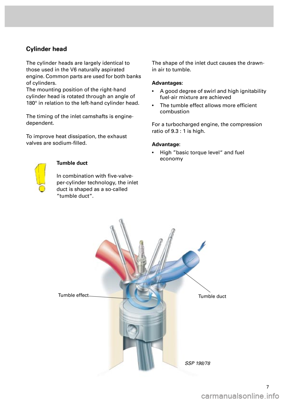
valves are sodium-filled.The shape of the inlet duct causes the drawn-
in air to tumble.
Advantages:
•
A good degree of swirl and high ignitability
fuel-air mixture are achieved
•
The tumble effect allows more efficient
combustion
For a turbocharged engine, the compression
ratio of 9.3 : 1 is high.
Advantage:
•
High ”basic torque level“ and fuel
economy
Tumble duct
In combination with five-valve-
per-cylinder technology, the inlet
duct is shaped as a so-called
“tumble duct“.
Tumble duct
Tumble effect
SSP 198/78
Page 8 of 72
8
Engine
The variable valve timing
The camshaft timing has been modified
compared to the 2.8-litre V6 engine to meet the
demands of turbocharging technology.
Variable valve timing with an adjustment angle
of 22° is used here for the first time in
turbocharged engines
.
Advantage:
•
A torque increase of approx. 10% is
achieved at the bottom and top ends of the
engine speed range.
•
Better emission levels and fuel
consumption figures.
The variable valve timing is activated by the
Motronic by means of camshaft adjustment
valves N205 and N208.The design and function of the
variable valve timing are already
described in Self-study Programmes
182 and 192.
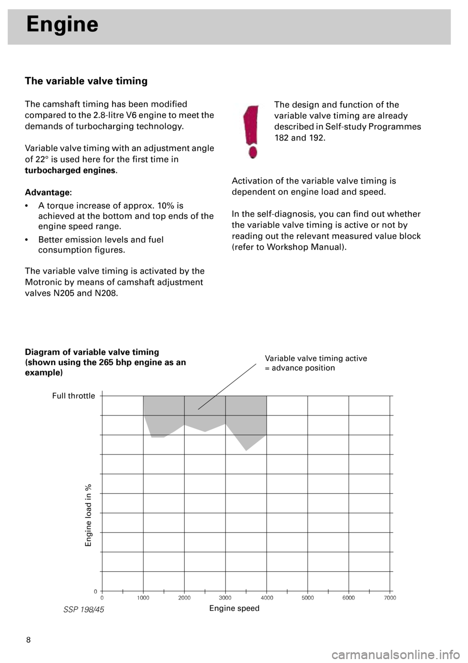
Activation of the variable valve timing is
dependent on engine load and speed.
In the self-diagnosis, you can find out whether
the variable valve timing is active or not by
reading out the relevant measured value block
(refer to Workshop Manual).
0
0 1000 2000 3000 4000 5000 6000 7000
SSP 198/45
Diagram of variable valve timing
(shown using the 265 bhp engine as an
example)
Engine speed
Engine load in %
Variable valve timing active
= advance position
Full throttle
Page 9 of 72
9
SSP 198/03
Cooling circuit
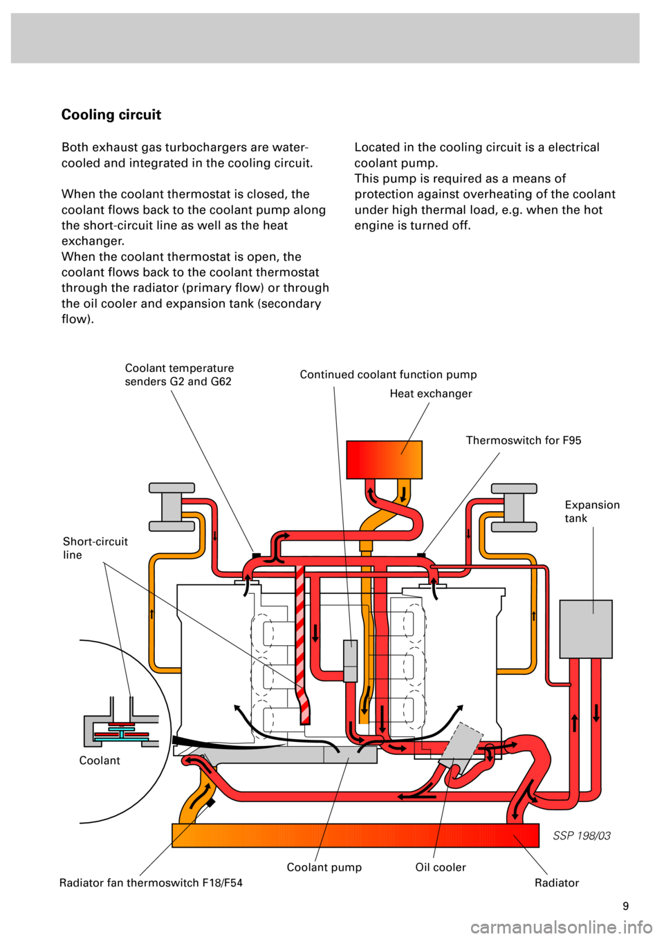
Both exhaust gas turbochargers are water-
cooled and integrated in the cooling circuit.
When the coolant thermostat is closed, the
coolant flows back to the coolant pump along
the short-circuit line as well as the heat
exchanger.
When the coolant thermostat is open, the
coolant flows back to the coolant thermostat
through the radiator (primary flow) or through
the oil cooler and expansion tank (secondary
flow).Located in the cooling circuit is a electrical
coolant pump.
This pump is required as a means of
protection against overheating of the coolant
under high thermal load, e.g. when the hot
engine is turned off.
Short-circuit
line
Continued coolant function pump
Heat exchanger
Coolant
Expansion
tank
Radiator fan thermoswitch F18/F54
Oil cooler
Radiator
Thermoswitch for F95
Coolant temperature
senders G2 and G62
Coolant pump
Page 10 of 72
10
SSP 198/10
Engine
Electrical coolant circulation pump V51
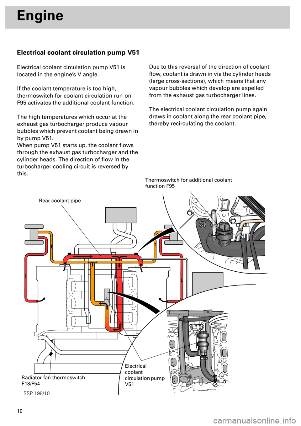
Electrical coolant circulation pump V51 is
located in the engine’s V angle.
If the coolant temperature is too high,
thermoswitch for coolant circulation run-on
F95 activates the additional coolant function.
The high temperatures which occur at the
exhaust gas turbocharger produce vapour
bubbles which prevent coolant being drawn in
by pump V51.
When pump V51 starts up, the coolant flows
through the exhaust gas turbocharger and the
cylinder heads. The direction of flow in the
turbocharger cooling circuit is reversed by
this.Due to this reversal of the direction of coolant
flow, coolant is drawn in via the cylinder heads
(large cross-sections), which means that any
vapour bubbles which develop are expelled
from the exhaust gas turbocharger lines.
The electrical coolant circulation pump again
draws in coolant along the rear coolant pipe,
thereby recirculating the coolant.
Rear coolant pipe
Electrical
coolant
circulation pump
V51
Thermoswitch for additional coolant
function F95
Radiator fan thermoswitch
F18/F54
Page 14 of 72
1415
SSP 198/49
Engine
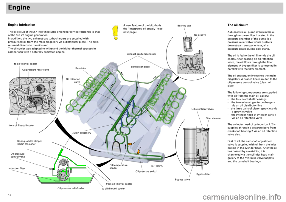
Engine lubrication
The oil circuit of the 2.7-litre V6 biturbo engine largely corresponds to that
of the 3rd V6 engine generation.
In addition, the two exhaust gas turbochargers are supplied with
pressurised oil from the main oil gallery via a distributor piece. The oil is
returned directly to the oil sump.
The oil cooler was adapted to withstand the higher thermal stresses in
comparison with a naturally aspirated engine.A new feature of the biturbo is
the “integrated oil supply“ (see
next page).
to oil filter/oil cooler
Spring-loaded slipper
(chain tensioner)
Main oil gallery
Oil retention valves
Bypass valve
Filter element
Bearing cap
Oil groove
Oil temperature
sender
Oil pressure switch
Restrictor
Oil retention
valve
distributor piece
The oil circuit
A duocentric oil pump draws in the oil
through a coarse filter. Located in the
pressure chamber of the pump is a
pressure relief valve which protects
downstream components against
pressure peaks during cold starts.
The oil is fed to the oil filter via the oil
cooler. After passing an oil retention
valve, the oil flows through the filter
element. A bypass filter is connected in
parallel with the filter element.
The oil subsequently reaches the main
oil gallery. A branch line is routed to the
oil pressure control valve (clean oil
side).
The following components are supplied
with oil from the main oil gallery:
- the four crankshaft bearings
- the two exhaust gas turbochargers
via an oil distributor line
- the three pairs of piston spray jets via
a spray jet valve
- the cylinder head of cylinder bank 1
via an oil retention valve
The cylinder head of cylinder bank 2 is
supplied through a separate bore from
crankshaft bearing 2 via an oil retention
valve also.
First of all, the camshaft adjustment
valve is supplied with oil from the inlet
drilling in the cylinder head. After the oil
has passed by a restrictor, it is
channeled via the cylinder head main
gallery to the hydraulic valve tappets
and the camshaft bearings.
Exhaust gas turbocharger
Bypass filter
Oil pressure relief valve
from oil filter/oil coolerOil pressure
control valveInduction filter
Oil pressure relief valve
from oil filter/oil cooler
to oil filter/oil cooler
Page 19 of 72
20
Engine
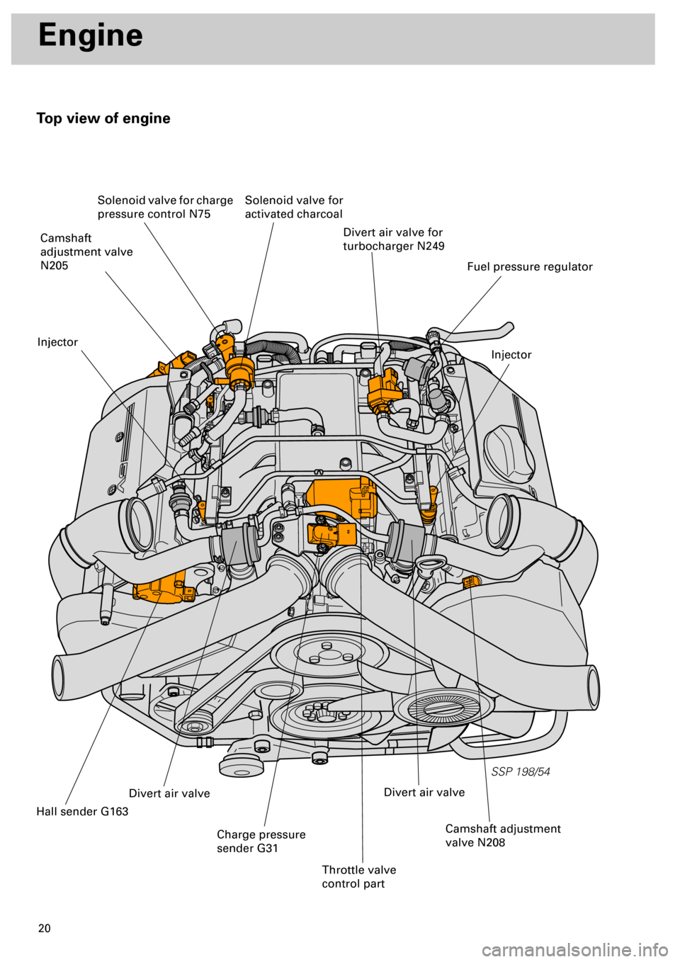
Top view of engine
SSP 198/54
Divert air valve for
turbocharger N249
Injector
Fuel pressure regulator
Solenoid valve for
activated charcoal Solenoid valve for charge
pressure control N75
Camshaft
adjustment valve
N205
Injector
Hall sender G163
Divert air valve
Charge pressure
sender G31
Throttle valve
control part
Camshaft adjustment
valve N208
Divert air valve