sensor AUDI S4 1998 B5 / 1.G Engine Manual
[x] Cancel search | Manufacturer: AUDI, Model Year: 1998, Model line: S4, Model: AUDI S4 1998 B5 / 1.GPages: 72, PDF Size: 3.25 MB
Page 3 of 72
3
This Self-study Programme provides you with information
regarding design and function.
The Self-study Programme is not a Workshop Manual!
Please refer to the Service Literature for all the relevant
maintenance and repair instructions.
Page
Engine .........................................................
Technical data, crankshaft, cylinder head,
camshaft timing, cooling circuit, engine
lubrication, overview of components, air ducting,
charging, exhaust system, pneumatically
controlled systems, charge pressure control, air
divert control in overrun, ACF system, crankcase
breather
4
Motronic ME 7.1 ..........................................
Subfunctions, system overview
31
Subsystems of the Motronic .....................
Torque-oriented engine management, torque-
oriented functional structure, Electronic throttle,
exhaust gas temperature control
33
Sensors .......................................................
Additional sensors of the Motronic
49
Auxiliary signals/interfaces ...................... 57
Functional diagram ..................................... 62
Self-diagnosis .............................................
Vehicle diagnosis, test and information system
VAS 5051, test box V.A.G 1598/31
64
Transmission ..............................................
Self-adjusting clutch, gearbox
66
Contents
Important!/Note!
New!
Page 17 of 72
18
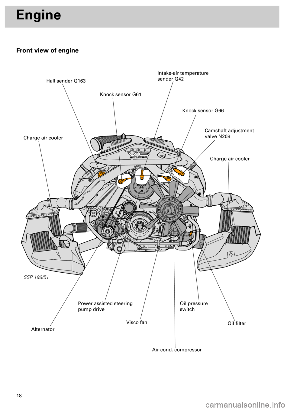
Front view of engine
SSP 198/51
Engine
Camshaft adjustment
valve N208
Knock sensor G66
Intake-air temperature
sender G42
Knock sensor G61
Hall sender G163
Charge air cooler
Charge air cooler
Oil filter
Oil pressure
switch
Air-cond. compressor
Visco fan
Alternator
Power assisted steering
pump drive
Page 23 of 72
24
SSP 198/33
Engine
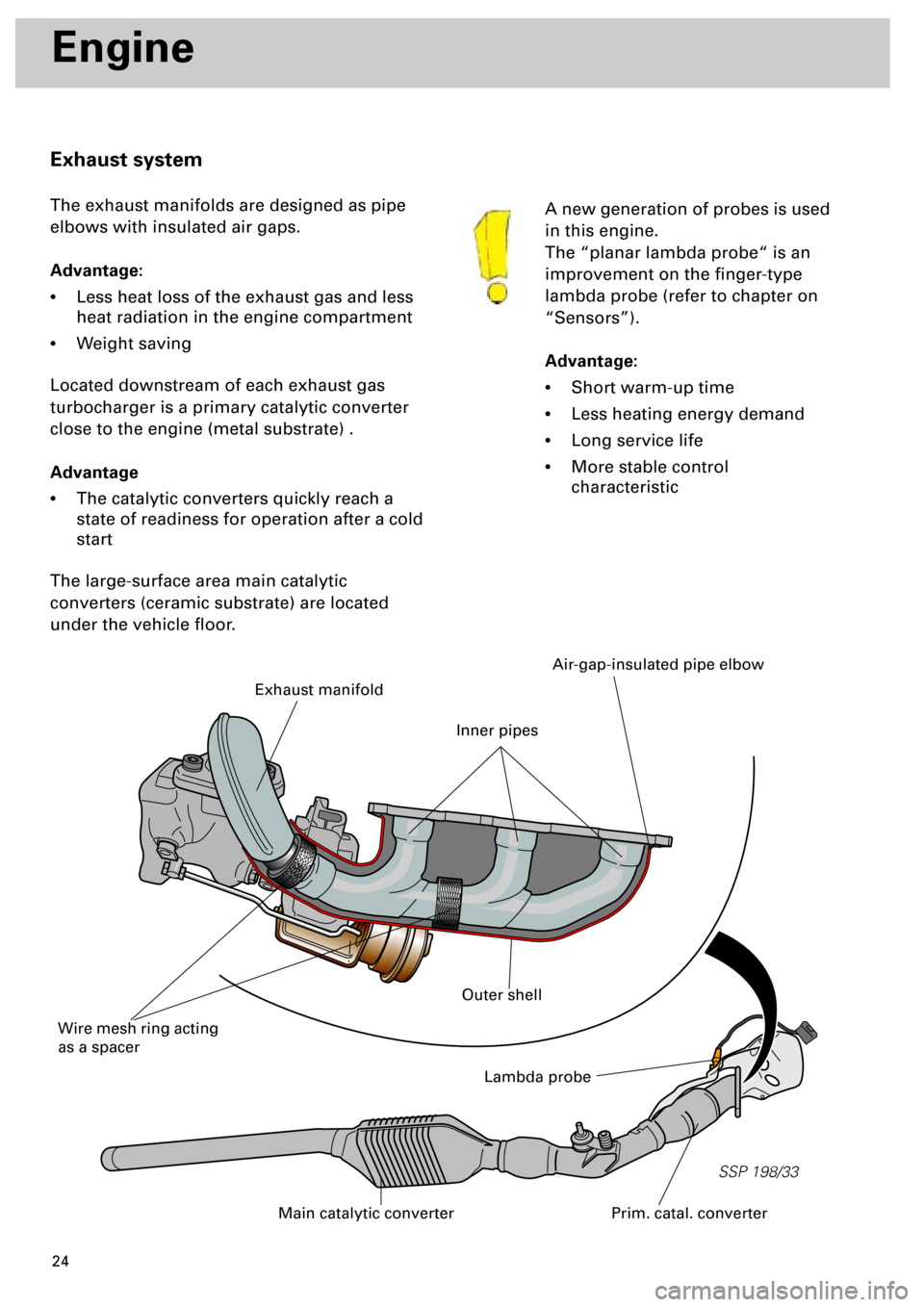
A new generation of probes is used
in this engine.
The “planar lambda probe“ is an
improvement on the finger-type
lambda probe (refer to chapter on
“Sensors”).
Advantage:
•
Short warm-up time
•
Less heating energy demand
•
Long service life
•
More stable control
characteristic
Exhaust system
The exhaust manifolds are designed as pipe
elbows with insulated air gaps.
Advantage:
•
Less heat loss of the exhaust gas and less
heat radiation in the engine compartment
•
Weight saving
Located downstream of each exhaust gas
turbocharger is a primary catalytic converter
close to the engine (metal substrate) .
Advantage
•
The catalytic converters quickly reach a
state of readiness for operation after a cold
start
The large-surface area main catalytic
converters (ceramic substrate) are located
under the vehicle floor.
Lambda probe
Prim. catal. converterMain catalytic converter
Exhaust manifold
Wire mesh ring acting
as a spacer
Air-gap-insulated pipe elbow
Outer shell
Inner pipes
Page 31 of 72
32
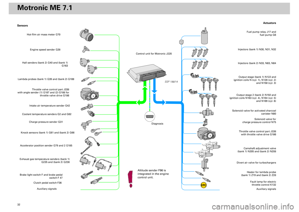
Actuators
Heater for lambda probe
(bank 1) Z19 and (bank 2) Z28
Divert air valve for turbochargers
Camshaft adjustment valve
(bank 1) N205 and (bank 2) N208
Throttle valve control part J338
with throttle valve drive G186
Solenoid valve for
charge pressure control N75
Solenoid valve for activated charcoal
canister N80
Output stage (bank 1) N122 and
ignition coils N (cyl. 1), N128 (cyl. 2)
and N158 (cyl. 3)Injectors (bank 1) N30, N31, N32
Fuel pump relay J17 and
fuel pump G6
Output stage 2 (bank 2) N192 and
ignition coils N163 (cyl. 4), N164 (cyl. 5)
and N189 (cyl. 6)
Fault lamp for electric
throttle control K132
Auxiliary signals
Sensors
Engine speed sender G28
Hall senders (bank 2) G40 and (bank 1)
G163
Lambda probes (bank 1) G39 and (bank 2) G108
Throttle valve control part J338
with angle sender (1) G187 and (2) G188 for
throttle valve drive G186
Intake air temperature sender G42
Coolant temperature senders G2 and G62
Charge pressure sender G31
Knock sensors (bank 1) G61 and (bank 2) G66Accelerator position sender G79 and 2 G185Exhaust gas temperature senders (bank 1)
G235 and (bank 2) G236Brake light switch F and brake pedal
switch F 47
Clutch pedal switch F36
Auxiliary signals
SSP 198/14
EPC
Injectors (bank 2) N33, N83, N84
Hot-film air mass meter G70
Control unit for Motronic J220
Altitude sender F96 is
integrated in the engine
control unit.
Diagnosis
Motronic ME 7.1
Page 44 of 72
45
SSP 198/34
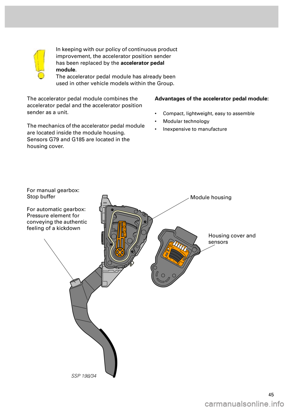
The accelerator pedal module combines the
accelerator pedal and the accelerator position
sender as a unit.
The mechanics of the accelerator pedal module
are located inside the module housing.
Sensors G79 and G185 are located in the
housing cover.In keeping with our policy of continuous product
improvement, the accelerator position sender
has been replaced by the
accelerator pedal
module
.
The accelerator pedal module has already been
used in other vehicle models within the Group.
Advantages of the accelerator pedal module:
• Compact, lightweight, easy to assemble
• Modular technology
• Inexpensive to manufacture
Module housing
Housing cover and
sensors
For manual gearbox:
Stop buffer
For automatic gearbox:
Pressure element for
conveying the authentic
feeling of a kickdown
Page 46 of 72
47
SSP/198/13
Exhaust gas temperature sender
G235 and G236
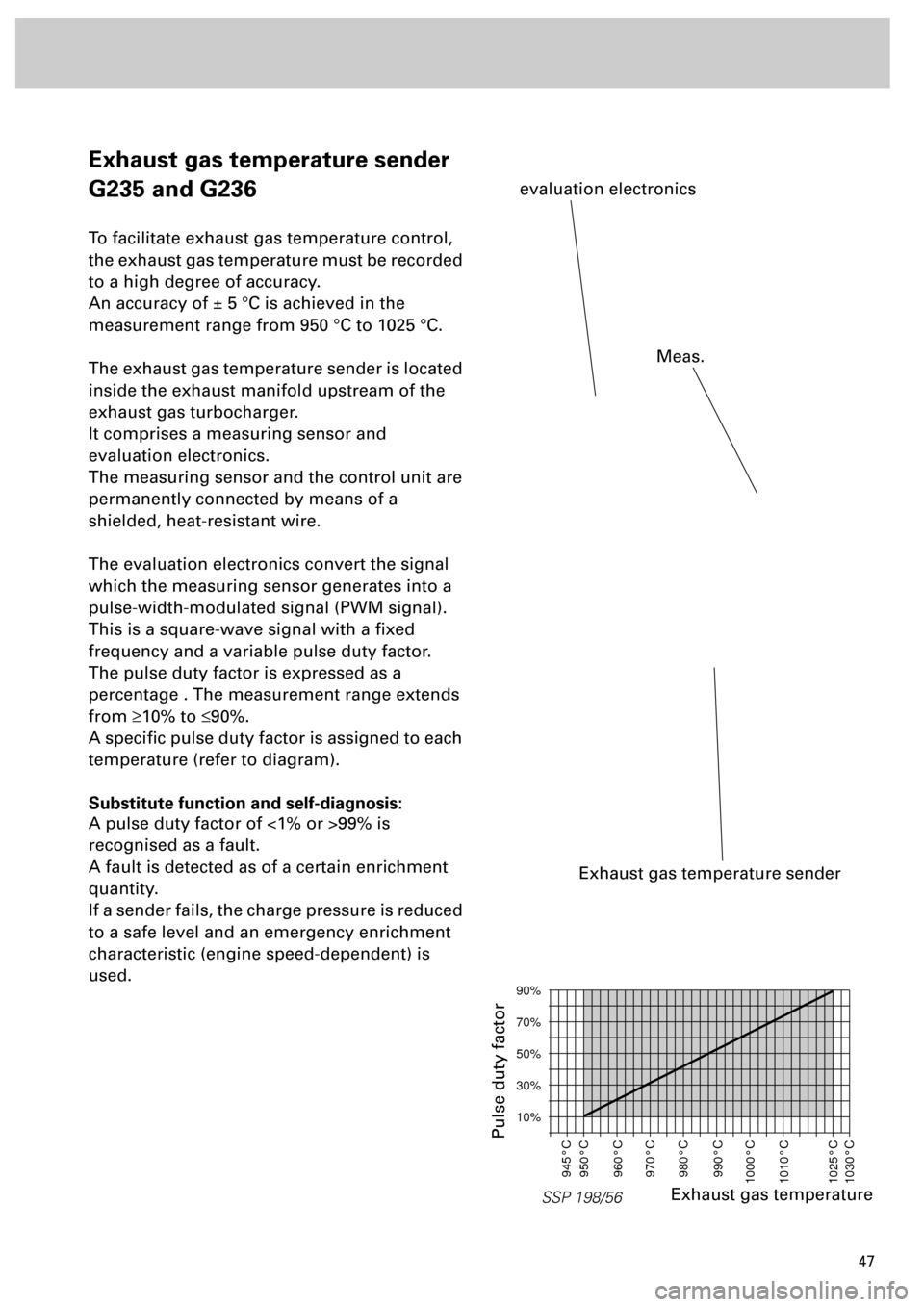
To facilitate exhaust gas temperature control,
the exhaust gas temperature must be recorded
to a high degree of accuracy.
An accuracy of ± 5 °C is achieved in the
measurement range from 950 °C to 1025 °C.
The exhaust gas temperature sender is located
inside the exhaust manifold upstream of the
exhaust gas turbocharger.
It comprises a measuring sensor and
evaluation electronics.
The measuring sensor and the control unit are
permanently connected by means of a
shielded, heat-resistant wire.
The evaluation electronics convert the signal
which the measuring sensor generates into a
pulse-width-modulated signal (PWM signal).
This is a square-wave signal with a fixed
frequency and a variable pulse duty factor.
The pulse duty factor is expressed as a
percentage . The measurement range extends
from
³
10% to
£
90%.
A specific pulse duty factor is assigned to each
temperature (refer to diagram).
Substitute function and self-diagnosis:
A pulse duty factor of <1% or >99% is
recognised as a fault.
A fault is detected as of a certain enrichment
quantity.
If a sender fails, the charge pressure is reduced
to a safe level and an emergency enrichment
characteristic (engine speed-dependent) is
used.
Exhaust gas temperature sender
evaluation electronics
SSP 198/56
90%
70%
50%
30%
10%
945°C
950°C
960°C
970°C
980°C
990°C
1000°C
1010°C
1025°C
1030°C
Exhaust gas temperature
Pulse duty factor
Meas.
Page 48 of 72
49
Sensors
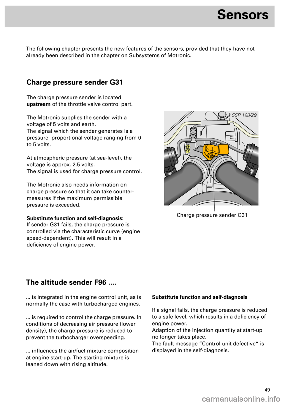
Charge pressure sender G31
The charge pressure sender is located
upstream of the throttle valve control part.
The Motronic supplies the sender with a
voltage of 5 volts and earth.
The signal which the sender generates is a
pressure- proportional voltage ranging from 0
to 5 volts.
At atmospheric pressure (at sea-level), the
voltage is approx. 2.5 volts.
The signal is used for charge pressure control.
The Motronic also needs information on
charge pressure so that it can take counter-
measures if the maximum permissible
pressure is exceeded.
Substitute function and self-diagnosis:
If sender G31 fails, the charge pressure is
controlled via the characteristic curve (engine
speed-dependent). This will result in a
deficiency of engine power.
SSP 198/29
Charge pressure sender G31
The altitude sender F96 ....
... is integrated in the engine control unit, as is
normally the case with turbocharged engines.
... is required to control the charge pressure. In
conditions of decreasing air pressure (lower
density), the charge pressure is reduced to
prevent the turbocharger overspeeding.
... influences the air/fuel mixture composition
at engine start-up. The starting mixture is
leaned down with rising altitude.Substitute function and self-diagnosis
If a signal fails, the charge pressure is reduced
to a safe level, which results in a deficiency of
engine power.
Adaption of the injection quantity at start-up
no longer takes place.
The fault message “Control unit defective“ is
displayed in the self-diagnosis.
The following chapter presents the new features of the sensors, provided that they have not
already been described in the chapter on Subsystems of Motronic.
Page 49 of 72
50
SSP 198/16
Sensors
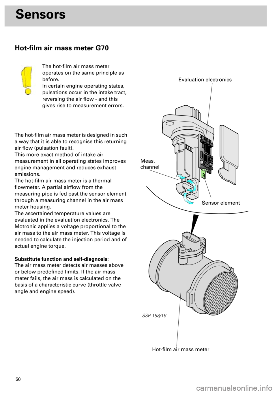
The hot-film air mass meter
operates on the same principle as
before.
In certain engine operating states,
pulsations occur in the intake tract,
reversing the air flow - and this
gives rise to measurement errors.
The hot-film air mass meter is designed in such
a way that it is able to recognise this returning
air flow (pulsation fault).
This more exact method of intake air
measurement in all operating states improves
engine management and reduces exhaust
emissions.
The hot-film air mass meter is a thermal
flowmeter. A partial airflow from the
measuring pipe is fed past the sensor element
through a measuring channel in the air mass
meter housing.
The ascertained temperature values are
evaluated in the evaluation electronics. The
Motronic applies a voltage proportional to the
air mass to the air mass meter. This voltage is
needed to calculate the injection period and of
actual engine torque.
Substitute function and self-diagnosis:
The air mass meter detects air masses above
or below predefined limits. If the air mass
meter fails, the air mass is calculated on the
basis of a characteristic curve (throttle valve
angle and engine speed).
Hot-film air mass meter
Sensor element
Meas.
channel
Evaluation electronics
Hot-film air mass meter G70
Page 50 of 72
51
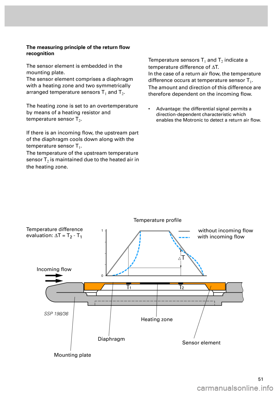
The measuring principle of the return flow
recognition
The sensor element is embedded in the
mounting plate.
The sensor element comprises a diaphragm
with a heating zone and two symmetrically
arranged temperature sensors T
1 and T2.
The heating zone is set to an overtemperature
by means of a heating resistor and
temperature sensor T
2.
If there is an incoming flow, the upstream part
of the diaphragm cools down along with the
temperature sensor T
1.
The temperature of the upstream temperature
sensor T
2 is maintained due to the heated air in
the heating zone.
Temperature sensors T1 and T2 indicate a
temperature difference of DT.
In the case of a return air flow, the temperature
difference occurs at temperature sensor T
1.
The amount and direction of this difference are
therefore dependent on the incoming flow.
• Advantage: the differential signal permits a
direction-dependent characteristic which
enables the Motronic to detect a return air flow.
T
T
1T2
1
0
SSP 198/36
Incoming flow
Temperature profile
without incoming flow
with incoming flow
Mounting plate
Diaphragm
Heating zone
Sensor element
Temperature difference
evaluation: DT = T
2 - T1
Page 51 of 72
52
Sensors
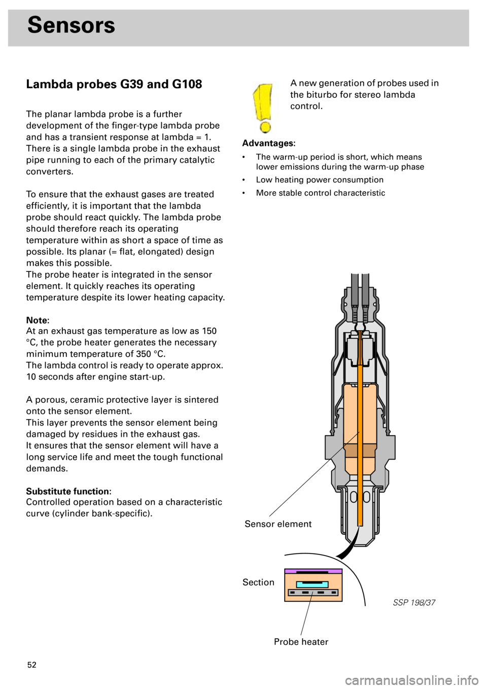
Lambda probes G39 and G108
The planar lambda probe is a further
development of the finger-type lambda probe
and has a transient response at lambda = 1.
There is a single lambda probe in the exhaust
pipe running to each of the primary catalytic
converters.
To ensure that the exhaust gases are treated
efficiently, it is important that the lambda
probe should react quickly. The lambda probe
should therefore reach its operating
temperature within as short a space of time as
possible. Its planar (= flat, elongated) design
makes this possible.
The probe heater is integrated in the sensor
element. It quickly reaches its operating
temperature despite its lower heating capacity.
Note:
At an exhaust gas temperature as low as 150
°C, the probe heater generates the necessary
minimum temperature of 350 °C.
The lambda control is ready to operate approx.
10 seconds after engine start-up.
A porous, ceramic protective layer is sintered
onto the sensor element.
This layer prevents the sensor element being
damaged by residues in the exhaust gas.
It ensures that the sensor element will have a
long service life and meet the tough functional
demands.
Substitute function:
Controlled operation based on a characteristic
curve (cylinder bank-specific).A new generation of probes used in
the biturbo for stereo lambda
control.
Advantages:
• The warm-up period is short, which means
lower emissions during the warm-up phase
• Low heating power consumption
• More stable control characteristic
SSP 198/37
Section
Probe heater
Sensor element