gearbox AUDI S4 1998 B5 / 1.G Engine Manual
[x] Cancel search | Manufacturer: AUDI, Model Year: 1998, Model line: S4, Model: AUDI S4 1998 B5 / 1.GPages: 72, PDF Size: 3.25 MB
Page 3 of 72
3
This Self-study Programme provides you with information
regarding design and function.
The Self-study Programme is not a Workshop Manual!
Please refer to the Service Literature for all the relevant
maintenance and repair instructions.
Page
Engine .........................................................
Technical data, crankshaft, cylinder head,
camshaft timing, cooling circuit, engine
lubrication, overview of components, air ducting,
charging, exhaust system, pneumatically
controlled systems, charge pressure control, air
divert control in overrun, ACF system, crankcase
breather
4
Motronic ME 7.1 ..........................................
Subfunctions, system overview
31
Subsystems of the Motronic .....................
Torque-oriented engine management, torque-
oriented functional structure, Electronic throttle,
exhaust gas temperature control
33
Sensors .......................................................
Additional sensors of the Motronic
49
Auxiliary signals/interfaces ...................... 57
Functional diagram ..................................... 62
Self-diagnosis .............................................
Vehicle diagnosis, test and information system
VAS 5051, test box V.A.G 1598/31
64
Transmission ..............................................
Self-adjusting clutch, gearbox
66
Contents
Important!/Note!
New!
Page 33 of 72
34
Subsystems of the Motronic
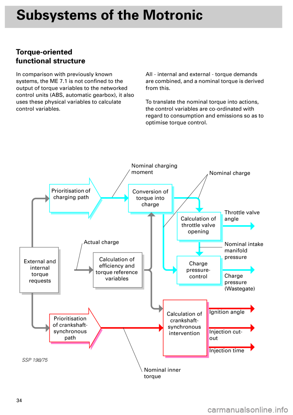
In comparison with previously known
systems, the ME 7.1 is not confined to the
output of torque variables to the networked
control units (ABS, automatic gearbox), it also
uses these physical variables to calculate
control variables.All - internal and external - torque demands
are combined, and a nominal torque is derived
from this.
To translate the nominal torque into actions,
the control variables are co-ordinated with
regard to consumption and emissions so as to
optimise torque control.
SSP 198/75
External and
internal
torque
requests
Calculation of
efficiency and
torque reference
variables
Prioritisation of
charging path
Prioritisation
of crankshaft-
synchronous
path
Conversion of
torque into
charge
Throttle valve
angle
Charge
pressure-
control
Calculation of
crankshaft-
synchronous
intervention
Calculation of
throttle valve
opening
Charge
pressure
(Wastegate)
Ignition angle
Injection cut-
out
Injection time
Nominal charging
moment
Nominal charge
Nominal intake
manifold
pressure
Nominal inner
torque
Actual charge
Torque-oriented
functional structure
Page 37 of 72
38
Subsystems of the Motronic
SSP 198/12
Accelerator position senders G79
and G185
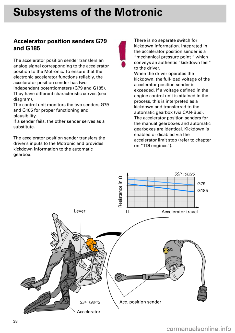
The accelerator position sender transfers an
analog signal corresponding to the accelerator
position to the Motronic. To ensure that the
electronic accelerator functions reliably, the
accelerator position sender has two
independent potentiometers (G79 and G185).
They have different characteristic curves (see
diagram).
The control unit monitors the two senders G79
and G185 for proper functioning and
plausibility.
If a sender fails, the other sender serves as a
substitute.
The accelerator position sender transfers the
driver’s inputs to the Motronic and provides
kickdown information to the automatic
gearbox.
Lever
Acc. position sender
AcceleratorThere is no separate switch for
kickdown information. Integrated in
the accelerator position sender is a
“mechanical pressure point “ which
conveys an authentic “kickdown feel”
to the driver.
When the driver operates the
kickdown, the full-load voltage of the
accelerator position sender is
exceeded. If a voltage defined in the
engine control unit is attained in the
process, this is interpreted as a
kickdown and transferred to the
automatic gearbox (via CAN-Bus).
The accelerator position senders for
the manual gearboxes and automatic
gearboxes are identical. Kickdown is
enabled or disabled via the
accelerator limit stop (refer to chapter
on “TDI engines”).
SSP 198/25
Resistance in
W
Accelerator travel
G79
G185
LL
Page 44 of 72
45
SSP 198/34
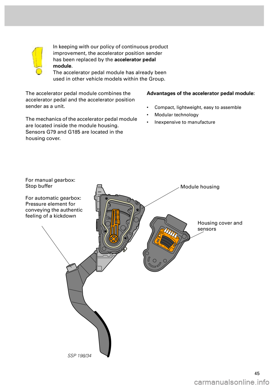
The accelerator pedal module combines the
accelerator pedal and the accelerator position
sender as a unit.
The mechanics of the accelerator pedal module
are located inside the module housing.
Sensors G79 and G185 are located in the
housing cover.In keeping with our policy of continuous product
improvement, the accelerator position sender
has been replaced by the
accelerator pedal
module
.
The accelerator pedal module has already been
used in other vehicle models within the Group.
Advantages of the accelerator pedal module:
• Compact, lightweight, easy to assemble
• Modular technology
• Inexpensive to manufacture
Module housing
Housing cover and
sensors
For manual gearbox:
Stop buffer
For automatic gearbox:
Pressure element for
conveying the authentic
feeling of a kickdown
Page 56 of 72
57
Additional signals/interfaces
Additional signals/interfaces to
Motronic ME 7.1
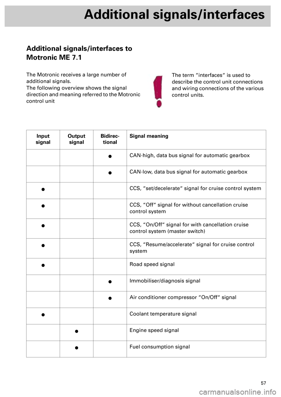
The Motronic receives a large number of
additional signals.
The following overview shows the signal
direction and meaning referred to the Motronic
control unit
Input
signalOutput
signalBidirec-
tionalSignal meaning
·CAN-high, data bus signal for automatic gearbox
·CAN-low, data bus signal for automatic gearbox
·CCS, “set/decelerate“ signal for cruise control system
·CCS, “Off“ signal for without cancellation cruise
control system
·CCS, “On/Off“ signal for with cancellation cruise
control system (master switch)
·CCS, “Resume/accelerate“ signal for cruise control
system
·Road speed signal
·Immobiliser/diagnosis signal
·Air conditioner compressor “On/Off“ signal
·Coolant temperature signal
·Engine speed signal
·Fuel consumption signal
The term “interfaces“ is used to
describe the control unit connections
and wiring connections of the various
control units.
Page 59 of 72
60
Additional signals/interface
The engine speed signal...
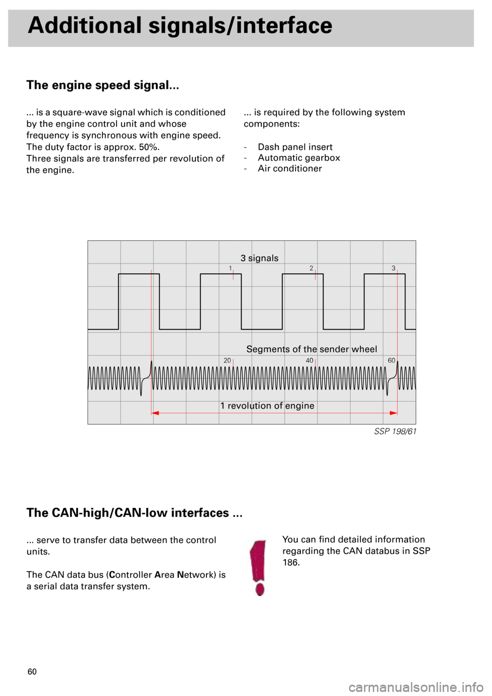
... is a square-wave signal which is conditioned
by the engine control unit and whose
frequency is synchronous with engine speed.
The duty factor is approx. 50%.
Three signals are transferred per revolution of
the engine.... is required by the following system
components:
- Dash panel insert
- Automatic gearbox
- Air conditioner
The CAN-high/CAN-low interfaces ...
... serve to transfer data between the control
units.
The CAN data bus (Controller Area Network) is
a serial data transfer system.You can find detailed information
regarding the CAN databus in SSP
186.
12
20 40 603
SSP 198/61
1 revolution of engineSegments of the sender wheel 3 signals
Page 61 of 72
62
Functional diagram
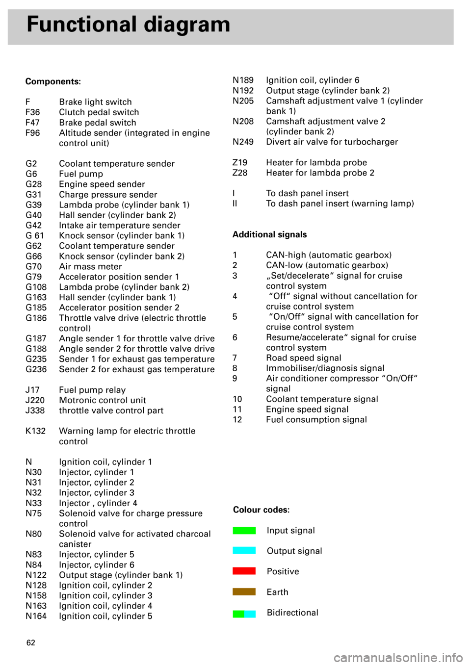
Components:
F Brake light switch
F36 Clutch pedal switch
F47 Brake pedal switch
F96 Altitude sender (integrated in engine
control unit)
G2 Coolant temperature sender
G6 Fuel pump
G28 Engine speed sender
G31 Charge pressure sender
G39 Lambda probe (cylinder bank 1)
G40 Hall sender (cylinder bank 2)
G42 Intake air temperature sender
G 61 Knock sensor (cylinder bank 1)
G62 Coolant temperature sender
G66 Knock sensor (cylinder bank 2)
G70 Air mass meter
G79 Accelerator position sender 1
G108 Lambda probe (cylinder bank 2)
G163 Hall sender (cylinder bank 1)
G185 Accelerator position sender 2
G186 Throttle valve drive (electric throttle
control)
G187 Angle sender 1 for throttle valve drive
G188 Angle sender 2 for throttle valve drive
G235 Sender 1 for exhaust gas temperature
G236 Sender 2 for exhaust gas temperature
J17 Fuel pump relay
J220 Motronic control unit
J338 throttle valve control part
K132 Warning lamp for electric throttle
control
N Ignition coil, cylinder 1
N30 Injector, cylinder 1
N31 Injector, cylinder 2
N32 Injector, cylinder 3
N33 Injector , cylinder 4
N75 Solenoid valve for charge pressure
control
N80 Solenoid valve for activated charcoal
canister
N83 Injector, cylinder 5
N84 Injector, cylinder 6
N122 Output stage (cylinder bank 1)
N128 Ignition coil, cylinder 2
N158 Ignition coil, cylinder 3
N163 Ignition coil, cylinder 4
N164 Ignition coil, cylinder 5N189 Ignition coil, cylinder 6
N192 Output stage (cylinder bank 2)
N205 Camshaft adjustment valve 1 (cylinder
bank 1)
N208 Camshaft adjustment valve 2
(cylinder bank 2)
N249 Divert air valve for turbocharger
Z19 Heater for lambda probe
Z28 Heater for lambda probe 2
I To dash panel insert
II To dash panel insert (warning lamp)
Additional signals
1 CAN-high (automatic gearbox)
2 CAN-low (automatic gearbox)
3 „Set/decelerate“ signal for cruise
control system
4 “Off“ signal without cancellation for
cruise control system
5 “On/Off“ signal with cancellation for
cruise control system
6 Resume/accelerate“ signal for cruise
control system
7 Road speed signal
8 Immobiliser/diagnosis signal
9 Air conditioner compressor “On/Off“
signal
10 Coolant temperature signal
11 Engine speed signal
12 Fuel consumption signal
Colour codes:
Input signal
Output signal
Positive
Earth
Bidirectional
Page 70 of 72
71
Gearbox
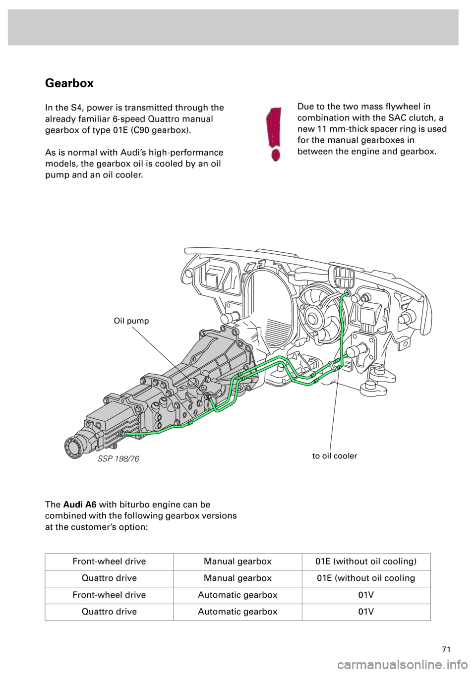
In the S4, power is transmitted through the
already familiar 6-speed Quattro manual
gearbox of type 01E (C90 gearbox).
As is normal with Audi’s high-performance
models, the gearbox oil is cooled by an oil
pump and an oil cooler.
The
Audi A6
with biturbo engine can be
combined with the following gearbox versions
at the customer’s option:
Front-wheel drive Manual gearbox 01E (without oil cooling)
Quattro drive Manual gearbox 01E (without oil cooling
Front-wheel drive Automatic gearbox 01V
Quattro drive Automatic gearbox 01V
Due to the two mass flywheel in
combination with the SAC clutch, a
new 11 mm-thick spacer ring is used
for the manual gearboxes in
between the engine and gearbox.
SSP 198/76
to oil cooler
Oil pump