heating AUDI S4 1998 B5 / 1.G Engine Manual
[x] Cancel search | Manufacturer: AUDI, Model Year: 1998, Model line: S4, Model: AUDI S4 1998 B5 / 1.GPages: 72, PDF Size: 3.25 MB
Page 9 of 72
9
SSP 198/03
Cooling circuit
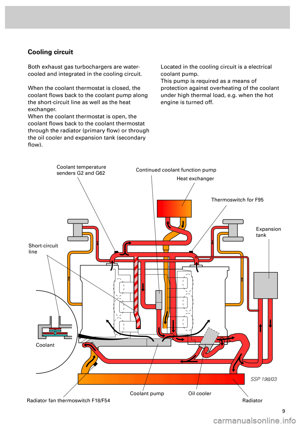
Both exhaust gas turbochargers are water-
cooled and integrated in the cooling circuit.
When the coolant thermostat is closed, the
coolant flows back to the coolant pump along
the short-circuit line as well as the heat
exchanger.
When the coolant thermostat is open, the
coolant flows back to the coolant thermostat
through the radiator (primary flow) or through
the oil cooler and expansion tank (secondary
flow).Located in the cooling circuit is a electrical
coolant pump.
This pump is required as a means of
protection against overheating of the coolant
under high thermal load, e.g. when the hot
engine is turned off.
Short-circuit
line
Continued coolant function pump
Heat exchanger
Coolant
Expansion
tank
Radiator fan thermoswitch F18/F54
Oil cooler
Radiator
Thermoswitch for F95
Coolant temperature
senders G2 and G62
Coolant pump
Page 23 of 72
24
SSP 198/33
Engine
A new generation of probes is used
in this engine.
The “planar lambda probe“ is an
improvement on the finger-type
lambda probe (refer to chapter on
“Sensors”).
Advantage:
•
Short warm-up time
•
Less heating energy demand
•
Long service life
•
More stable control
characteristic
Exhaust system
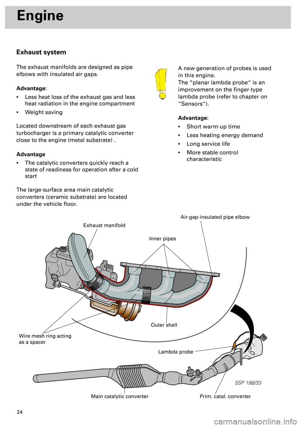
The exhaust manifolds are designed as pipe
elbows with insulated air gaps.
Advantage:
•
Less heat loss of the exhaust gas and less
heat radiation in the engine compartment
•
Weight saving
Located downstream of each exhaust gas
turbocharger is a primary catalytic converter
close to the engine (metal substrate) .
Advantage
•
The catalytic converters quickly reach a
state of readiness for operation after a cold
start
The large-surface area main catalytic
converters (ceramic substrate) are located
under the vehicle floor.
Lambda probe
Prim. catal. converterMain catalytic converter
Exhaust manifold
Wire mesh ring acting
as a spacer
Air-gap-insulated pipe elbow
Outer shell
Inner pipes
Page 32 of 72
33
SSP/198/15
Subsystems of the Motronic
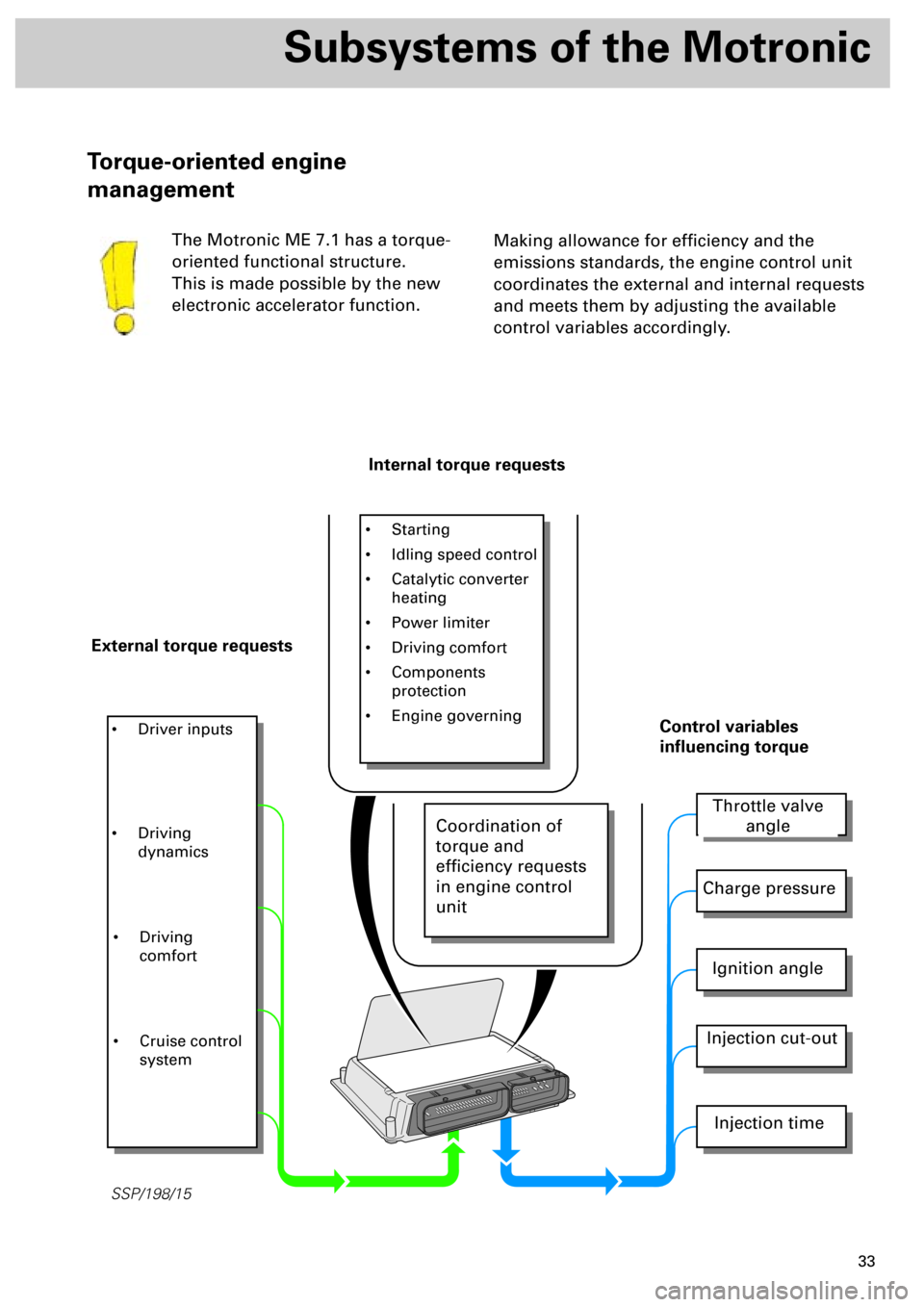
Making allowance for efficiency and the
emissions standards, the engine control unit
coordinates the external and internal requests
and meets them by adjusting the available
control variables accordingly.
Torque-oriented engine
management
The Motronic ME 7.1 has a torque-
oriented functional structure.
This is made possible by the new
electronic accelerator function.
Internal torque requests
External torque requests
• Starting
• Idling speed control
• Catalytic converter
heating
• Power limiter
• Driving comfort
• Components
protection
• Engine governing
• Driver inputs
Throttle valve
angle
Charge pressure
Ignition angle
Injection cut-out
Injection time
Control variables
influencing torque
• Driving
dynamics
• Driving
comfort
• Cruise control
system
Coordination of
torque and
efficiency requests
in engine control
unit
Page 50 of 72
51
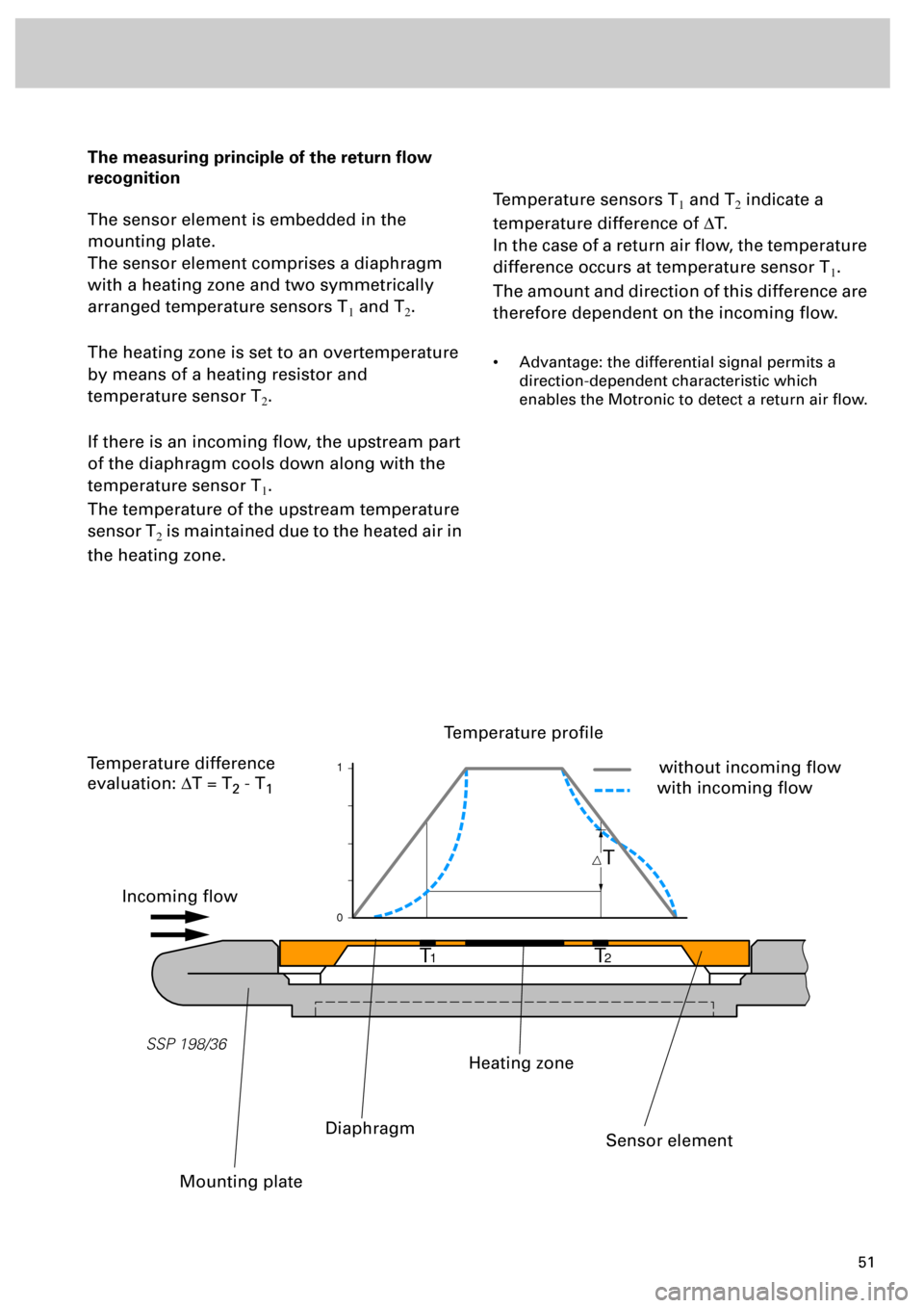
The measuring principle of the return flow
recognition
The sensor element is embedded in the
mounting plate.
The sensor element comprises a diaphragm
with a heating zone and two symmetrically
arranged temperature sensors T
1 and T2.
The heating zone is set to an overtemperature
by means of a heating resistor and
temperature sensor T
2.
If there is an incoming flow, the upstream part
of the diaphragm cools down along with the
temperature sensor T
1.
The temperature of the upstream temperature
sensor T
2 is maintained due to the heated air in
the heating zone.
Temperature sensors T1 and T2 indicate a
temperature difference of DT.
In the case of a return air flow, the temperature
difference occurs at temperature sensor T
1.
The amount and direction of this difference are
therefore dependent on the incoming flow.
• Advantage: the differential signal permits a
direction-dependent characteristic which
enables the Motronic to detect a return air flow.
T
T
1T2
1
0
SSP 198/36
Incoming flow
Temperature profile
without incoming flow
with incoming flow
Mounting plate
Diaphragm
Heating zone
Sensor element
Temperature difference
evaluation: DT = T
2 - T1
Page 51 of 72
52
Sensors
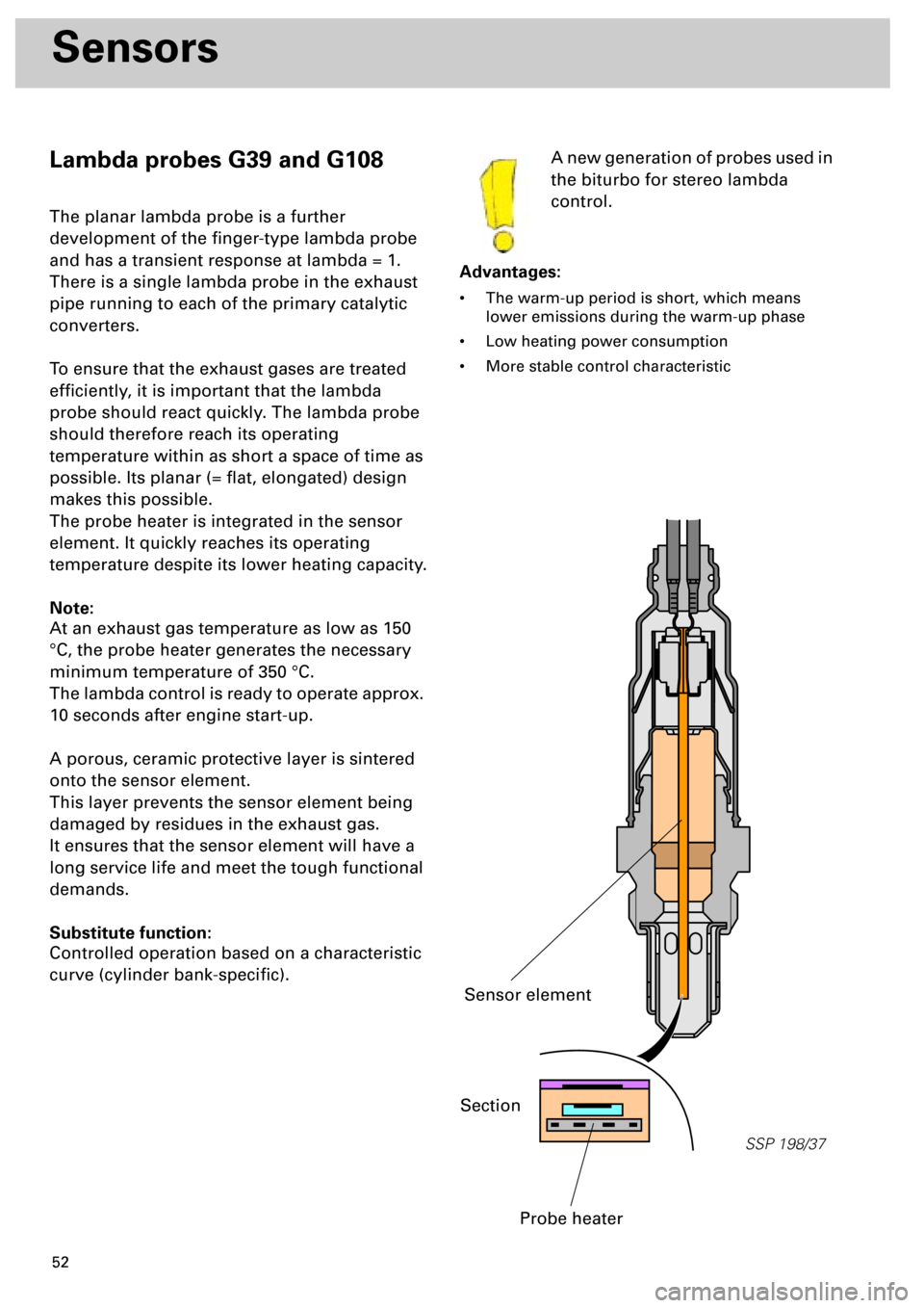
Lambda probes G39 and G108
The planar lambda probe is a further
development of the finger-type lambda probe
and has a transient response at lambda = 1.
There is a single lambda probe in the exhaust
pipe running to each of the primary catalytic
converters.
To ensure that the exhaust gases are treated
efficiently, it is important that the lambda
probe should react quickly. The lambda probe
should therefore reach its operating
temperature within as short a space of time as
possible. Its planar (= flat, elongated) design
makes this possible.
The probe heater is integrated in the sensor
element. It quickly reaches its operating
temperature despite its lower heating capacity.
Note:
At an exhaust gas temperature as low as 150
°C, the probe heater generates the necessary
minimum temperature of 350 °C.
The lambda control is ready to operate approx.
10 seconds after engine start-up.
A porous, ceramic protective layer is sintered
onto the sensor element.
This layer prevents the sensor element being
damaged by residues in the exhaust gas.
It ensures that the sensor element will have a
long service life and meet the tough functional
demands.
Substitute function:
Controlled operation based on a characteristic
curve (cylinder bank-specific).A new generation of probes used in
the biturbo for stereo lambda
control.
Advantages:
• The warm-up period is short, which means
lower emissions during the warm-up phase
• Low heating power consumption
• More stable control characteristic
SSP 198/37
Section
Probe heater
Sensor element