ron AUDI S4 2008 Owner's Guide
[x] Cancel search | Manufacturer: AUDI, Model Year: 2008, Model line: S4, Model: AUDI S4 2008Pages: 342, PDF Size: 15.01 MB
Page 66 of 342
Lights and vision
64Clear visionSun visors
The sun visors can improve vi sibility and contribute to
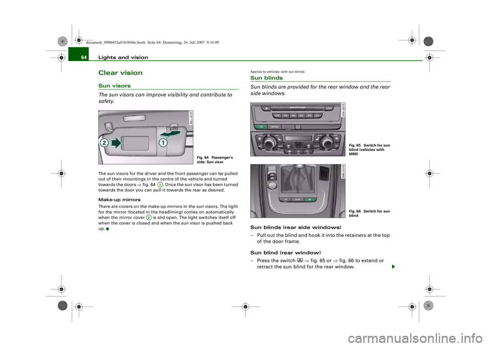
safety.The sun visors for the driver and the front passenger can be pulled
out of their mountings in the centre of the vehicle and turned
towards the doors ⇒fig. 64 . Once the sun visor has been turned
towards the door you can pull it towards the rear as desired.
Make-up mirrors
There are covers on the make-up mirrors in the sun visors. The light
for the mirror (located in the headlining) comes on automatically
when the mirror cover is slid open. The light switches itself off
when the cover is closed and when the sun visor is pushed back
up.
Applies to vehicles: with sun blindsSun blinds
Sun blinds are provided for the rear window and the rear
side windows.Sun blinds (rear side windows)
– Pull out the blind and hook it into the retainers at the top of the door frame.
Sun blind (rear window)
– Press the switch
⇒ fig. 65 or ⇒ fig. 66 to extend or
retract the sun blind for the rear window.
Fig. 64 Passenger's
side: Sun visor
A1
A2
Fig. 65 Switch for sun
blind (vehicles with
MMI)Fig. 66 Switch for sun
blind
document_0900452a81b1b9de.book Seite 64 Donnerstag, 26. Juli 2007 9:16 09
--4 -
-T
-+ +-
•
Page 70 of 342
Lights and vision
68when they are in the service position you will also avoid damaging
the paintwork on the bonnet.•
off - the windscreen wipers will be moved back to their original
position.Caution
Never move the vehicle with the front wiper arms in a raised posi-
tion as they are automatically moved back to their normal park posi-
tion above a speed of 6 km/h. The paintwork on the bonnet may be
damaged as a result.
Note
•
You can also use the service position, for example, if you want to
fix a cover over the windscreen in the winter to keep it clear of ice.
•
The service position is automatically set to off when you operate
the windscreen wiper lever or the road speed exceeds 6 km/h.
Changing wiper blades
Good wiper blades are essential for clear vision.Taking off the wiper blade
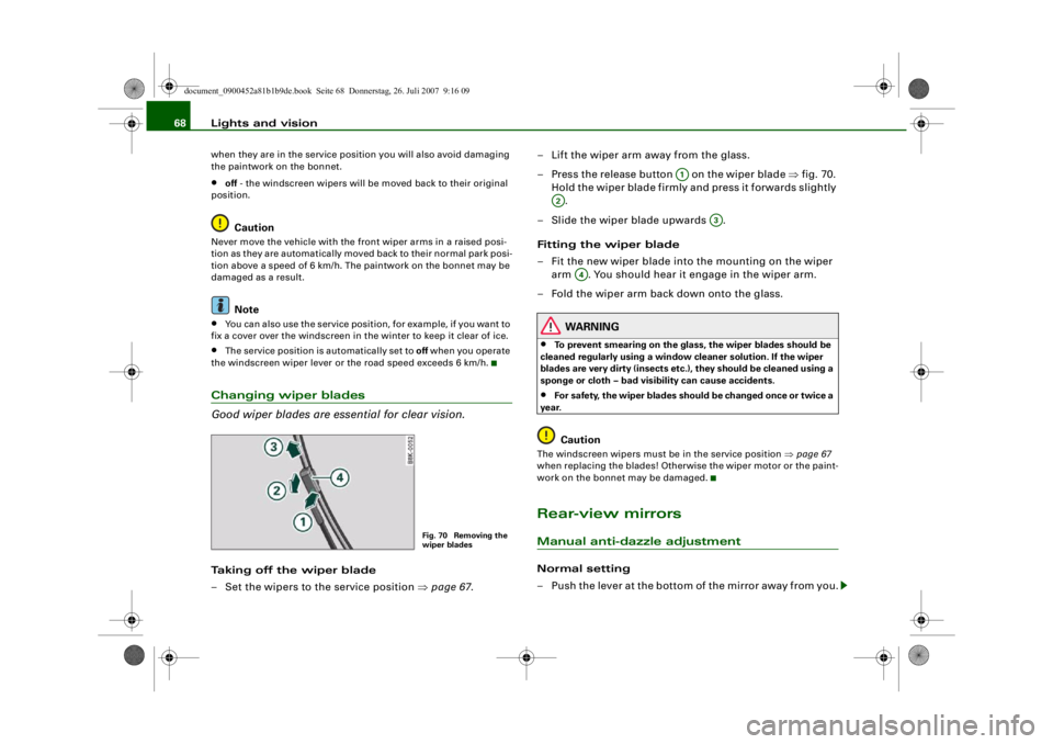
– Set the wipers to the service position ⇒page 67 . – Lift the wiper arm away from the glass.
– Press the release button on the wiper blade
⇒fig. 70.
Hold the wiper blade firmly and press it forwards slightly .
– Slide the wiper blade upwards .
Fitting the wiper blade
– Fit the new wiper blade into the mounting on the wiper
arm . You should hear it engage in the wiper arm.
– Fold the wiper arm back down onto the glass.
WARNING
•
To prevent smearing on the glas s, the wiper blades should be
cleaned regularly using a window cleaner solution. If the wiper
blades are very dirty (i nsects etc.), they should be cleaned using a
sponge or cloth – bad visibility can cause accidents.
•
For safety, the wiper blades shou ld be changed once or twice a
year.Caution
The windscreen wipers must be in the service position ⇒page 67
when replacing the blades! Otherwise the wiper motor or the paint-
work on the bonnet may be damaged.Rear-view mirrorsManual anti-dazzle adjustmentNormal setting
– Push the lever at the bottom of the mirror away from you.
Fig. 70 Removing the
wiper blades
A1
A2
A3
A4
document_0900452a81b1b9de.book Seite 68 Donnerstag, 26. Juli 2007 9:16 09
--4 -
-T
0 [I)
&
-+
•
+-
0
•
Page 71 of 342
Lights and vision69
Controls
Safety
Driving tips
General maintenance
Self-help
Technical data
Anti-dazzle setting
– Pull the lever at the bottom of the mirror towards you.Applies to vehicles: with automatic anti-dazzle adjustment for interior mirrorAutomatic anti-dazzle adjustment
The automatic anti-dazzle function can be switched on
and off as desired.Switching off anti-dazzle function
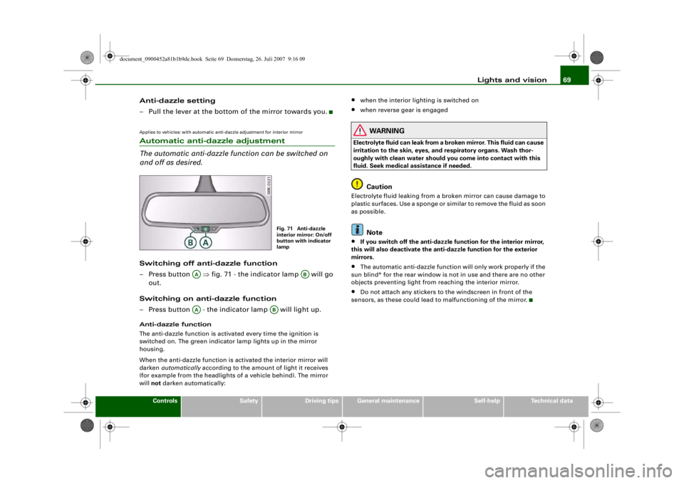
– Press button ⇒fig. 71 - the indicator lamp will go
out.
Switching on anti-dazzle function
– Press button - the indicator lamp will light up.Anti-dazzle function
The anti-dazzle function is activa ted every time the ignition is
switched on. The green indicator lamp lights up in the mirror
housing.
When the anti-dazzle function is ac tivated the interior mirror will
darken automatically according to the amount of light it receives
(for example from the headlights of a vehicle behind). The mirror
will not darken automatically:
•
when the interior lighting is switched on
•
when reverse gear is engaged
WARNING
Electrolyte fluid can leak from a br oken mirror. This fluid can cause
irritation to the skin, eyes, and respiratory organs. Wash thor-
oughly with clean water should you come into contact with this
fluid. Seek medical assistance if needed.
Caution
Electrolyte fluid leaking from a broken mirror can cause damage to
plastic surfaces. Use a sponge or similar to remove the fluid as soon
as possible.
Note
•
If you switch off the anti-dazzle function for the interior mirror,
this will also deactivate the anti -dazzle function for the exterior
mirrors.
•
The automatic anti-dazzle function will only work properly if the
sun blind* for the rear window is not in use and there are no other
objects preventing light from reaching the interior mirror.
•
Do not attach any stickers to the windscreen in front of the
sensors, as these could lead to malfunctioning of the mirror.
Fig. 71 Anti-dazzle
interior mirror: On/off
button with indicator
lamp
AA
AB
AA
AB
document_0900452a81b1b9de.book Seite 69 Donnerstag, 26. Juli 2007 9:16 09
--4 -
-T
•
-+
[I]
+-
•
Page 75 of 342
Seats and storage73
Controls
Safety
Driving tips
General maintenance
Self-help
Technical data
Seats and storageManual adjustment of front seatsApplies to vehicles: with manual seat adjustmentSeat adjuster controls
There are several seat adjustment functions for your
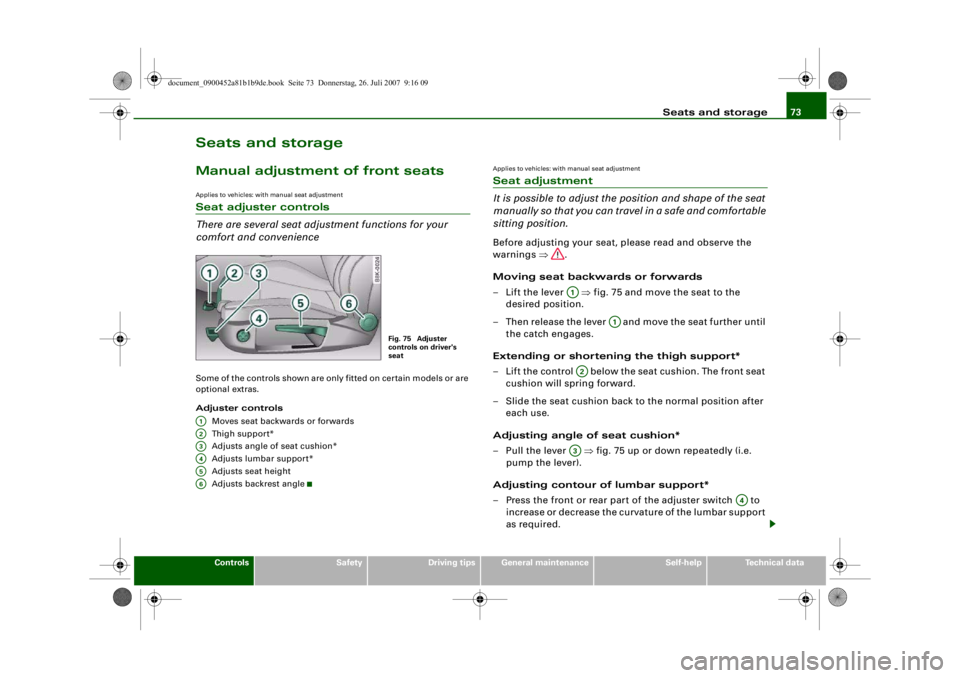
comfort and convenienceSome of the controls shown are only fitted on certain models or are
optional extras.
Adjuster controls
Moves seat backwards or forwards
Thigh suppor t*
Adjusts angle of seat cushion*
Adjusts lumbar support*
Adjusts seat height
Adjusts backrest angle
Applies to vehicles: with manual seat adjustmentSeat adjustment
It is possible to adjust the position and shape of the seat
manually so that you can travel in a safe and comfortable
sitting position.Before adjusting your seat, please read and observe the
warnings ⇒.
Moving seat backwards or forwards
– Lift the lever ⇒fig. 75 and move the seat to the
desired position.
– Then release the lever and move the seat further until the catch engages.
Extending or shortening the thigh support*
– Lift the control below the seat cushion. The front seat cushion will spring forward.
– Slide the seat cushion back to the normal position after each use.
Adjusting angle of seat cushion*
– Pull the lever ⇒fig. 75 up or down repeatedly (i.e.
pump the lever).
Adjusting contour of lumbar support*
– Press the front or rear part of the adjuster switch to
increase or decrease the curvature of the lumbar support
as required.
Fig. 75 Adjuster
controls on driver's
seat
A1A2A3A4A5A6
A1
A1
A2A3
A4
document_0900452a81b1b9de.book Seite 73 Donnerstag, 26. Juli 2007 9:16 09
--4 -
-T
-+ +-
•
Page 76 of 342
Seats and storage
74
Adjusting height of lumbar support*
– Press the top or bottom part of the adjuster switch to move the lumbar support upwards or downwards as
required.
Raising or lowering the seat
– Pull the lever ⇒page 73, fig. 75 up or down repeat-
edly (i.e. pump the lever).
Adjusting backrest angle
– Lean forwards to take your weight off the backrest.
– Turn the adjuster wheel ⇒ page 73, fig. 75 to set the
angle of the backrest as required.
WARNING
•
Never adjust the driver's seat wh en the vehicle is moving - this
could lead to an accident.
•
Be careful when adjusting the seat height. Careless or uncon-
trolled use of the seat adjustment can cause injuries.
•
Do not drive with the backrests of the front seats reclined too
far as otherwise the seat belt and airbag could fail to restrain the
wearer properly in an accident, possibly leading to injury.
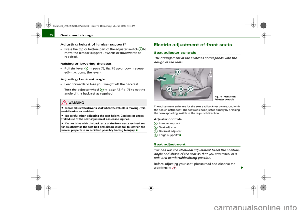
Electric adjustment of front seatsSeat adjuster controls
The arrangement of the switches corresponds with the
design of the seats.The adjustment switches for the se at and backrest correspond with
the design of the seat. The seats can be adjusted simply by pressing
the corresponding switch in the required direction.
Adjuster controls
Lumbar support
Seat adjuster
Backrest adjuster
Thigh suppor t*Seat adjustment
You can use the electrical adjustment to set the position,
angle and shape of the seat so that you can travel in a
safe and comfortable sitting position.Before adjusting your seat, please read and observe the
warnings ⇒.
A4
A5
A6
Fig. 76 Front seat:
Adjuster controls
AAABACAD
document_0900452a81b1b9de.book Seite 74 Donnerstag, 26. Juli 2007 9:16 09
--4 -
-T
-+ +-
•
•
Page 77 of 342
Seats and storage75
Controls
Safety
Driving tips
General maintenance
Self-help
Technical data
Adjusting contour of lumbar support
– Press the front or rear of switch to increase or
decrease the curvature of the lumbar support as
required.
Adjusting height of lumbar support
– Press the top or bottom of adjuster switch to move the lumbar support upwards or downwards as required.
Moving seat backwards or forwards
– Press switch ⇒page 74, fig. 76 forwards or back-
wards.
Adjusting seat height
– Press switch up or down.
Raising/lowering seat at front
– Press the front of switch up or down.
Raising/lowering seat at rear
– Press the rear of switch up or down.
Adjusting backrest angle
– Press switch forwards or backwards.
Extending or shortening the thigh support*
– Lift the control below the seat cushion. The front seat cushion will spring forward.
– Slide the seat cushion back to the normal position after each use.
WARNING
•
Never adjust the driver's seat wh en the vehicle is moving - this
could lead to an accident.
•
The electrical seat adjustment al so works when the ignition is
off and when the key is not in the ignition. To avoid accidental inju-
ries, never leave children unattended in the vehicle.
•
Be careful when adjusting the seat height. Careless or uncon-
trolled use of the height ad justment can cause injuries.
•
Do not drive with the backrests of the front seats reclined too
far as otherwise the seat belt and airbag could fail to restrain the
wearer properly in an accident, possibly leading to injury.
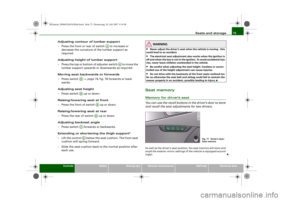
Seat memoryMemory for driver's seat
You can use the recall buttons in the driver's door to store
and recall the seat adjustments for two drivers.As well as the driver's seat position, the seat memory will store and
recall the exterior mirror settings (if the vehicle is equipped accord-
ingly):
AA
AA
ABAB
ABAB
ACAD
Fig. 77 Driver's door:
Seat memory
document_0900452a81b1b9de.book Seite 75 Donnerstag, 26. Juli 2007 9:16 09
--4 -
-T
•
-+ +-
Page 79 of 342
Seats and storage77
Controls
Safety
Driving tips
General maintenance
Self-help
Technical data
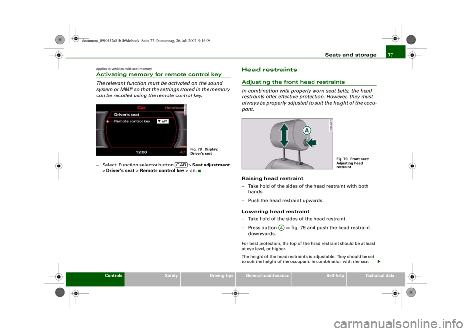
Applies to vehicles: with seat memoryActivating memory for remote control key
The relevant function must be activated on the sound
system or MMI* so that the settings stored in the memory
can be recalled using the remote control key.– Select: Function selector button > Seat adjustment
> Driver's seat > Remote control key > on.
Head restraintsAdjusting the front head restraints
In combination with properly worn seat belts, the head
restraints offer effective protection. However, they must
always be properly adjusted to suit the height of the occu-
pant.Raising head restraint
– Take hold of the sides of the head restraint with both
hands.
– Push the head restraint upwards.
Lowering head restraint
– Take hold of the sides of the head restraint.
– Press button ⇒fig. 79 and push the head restraint
downwards.For best protection, the top of the head restraint should be at least
at eye level, or higher.
The height of the head restraints is adjustable. They should be set
to suit the height of the occupa nt. In combination with the seat
Fig. 78 Display:
Driver's seat
CAR
Fig. 79 Front seat:
Adjusting head
restraint
AA
document_0900452a81b1b9de.book Seite 77 Donnerstag, 26. Juli 2007 9:16 09
--4 -
-T
-+
•
+-
Page 80 of 342
Seats and storage
78belts, the head restraints offer effective protection, provided they
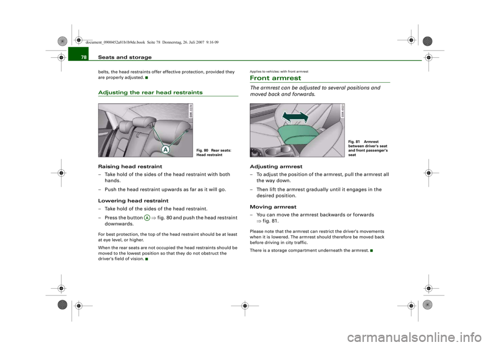
are properly adjusted.Adjusting the rear head restraintsRaising head restraint
– Take hold of the sides of the head restraint with both
hands.
– Push the head restraint upwards as far as it will go.
Lowering head restraint
– Take hold of the sides of the head restraint.
– Press the button ⇒fig. 80 and push the head restraint
downwards.For best protection, the top of the head restraint should be at least
at eye level, or higher.
When the rear seats are not occupied the head restraints should be
moved to the lowest position so that they do not obstruct the
driver's field of vision.
Applies to vehicles: with front armrestFront armrestThe armrest can be adjusted to several positions and
moved back and forwards.Adjusting armrest
– To adjust the position of the armrest, pull the armrest all the way down.
– Then lift the armrest gradually until it engages in the desired position.
Moving armrest
– You can move the armrest backwards or forwards ⇒fig. 81.Please note that the armrest can restrict the driver's movements
when it is lowered. The armrest should therefore be moved back
before driving in city traffic.
There is a storage compartment underneath the armrest.
Fig. 80 Rear seats:
Head restraint
AA
Fig. 81 Armrest
between driver's seat
and front passenger's
seat
document_0900452a81b1b9de.book Seite 78 Donnerstag, 26. Juli 2007 9:16 09
--4 -
-T
•
-+ +-
•
•
Page 82 of 342
Seats and storage
80
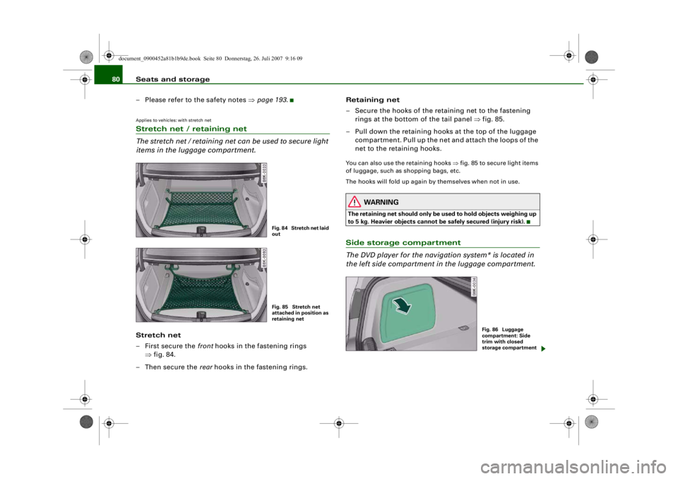
– Please refer to the safety notes ⇒page 193 .Applies to vehicles: with stretch netStretch net / retaining net
The stretch net / retaining net can be used to secure light
items in the luggage compartment.Stretch net
– First secure the front hooks in the fastening rings
⇒ fig. 84.
–Then secure the rear hooks in the fastening rings. Retaining net
– Secure the hooks of the retaining net to the fastening
rings at the bottom of the tail panel ⇒fig. 85.
– Pull down the retaining hooks at the top of the luggage compartment. Pull up the net and attach the loops of the
net to the retaining hooks.
You can also use the retaining hooks ⇒fig. 85 to secure light items
of luggage, such as shopping bags, etc.
The hooks will fold up again by themselves when not in use.
WARNING
The retaining net should only be used to hold objects weighing up
to 5 kg. Heavier objects cannot be safely secured (injury risk).Side storage compartment
The DVD player for the naviga tion system* is located in
the left side compartment in the luggage compartment.
Fig. 84 Stretch net laid
outFig. 85 Stretch net
attached in position as
retaining net
Fig. 86 Luggage
compartment: Side
trim with closed
storage compartment
document_0900452a81b1b9de.book Seite 80 Donnerstag, 26. Juli 2007 9:16 09
--4 -
-
•
T
-+
Page 86 of 342
Seats and storage
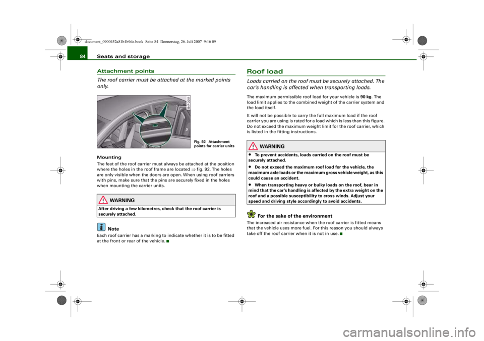
84Attachment points
The roof carrier must be attached at the marked points
only.Mounting
The feet of the roof carrier must always be attached at the position
where the holes in the roof frame are located ⇒fig. 92. The holes
are only visible when the doors are open. When using roof carriers
with pins, make sure that the pins are securely fixed in the holes
when mounting the carrier units.
WARNING
After driving a few kilometres, check that the roof carrier is
securely attached.
Note
Each roof carrier has a marking to indicate whether it is to be fitted
at the front or rear of the vehicle.
Roof loadLoads carried on the roof must be securely attached. The
car's handling is affected when transporting loads.The maximum permissible roof load for your vehicle is 90 kg. The
load limit applies to the combined weight of the carrier system and
the load itself.
It will not be possible to carry the full maximum load if the roof
carrier you are using is rated for a load which is less than this figure.
Do not exceed the maximum weight limit for the roof carrier, which
is listed in the fitting instructions.
WARNING
•
To prevent accidents, loads ca rried on the roof must be
securely attached.
•
Do not exceed the maximum roof load for the vehicle, the
maximum axle loads or the maximu m gross vehicle weight, as this
could cause an accident.
•
When transporting heavy or bulky loads on the roof, bear in
mind that the car's handling is affected by the extra weight on the
roof and a possible susceptibility to cross winds. Adjust your
speed and driving style acco rdingly to avoid accidents.For the sake of the environment
The increased air resistance when the roof carrier is fitted means
that the vehicle uses more fuel. Fo r this reason you should always
take off the roof carrier when it is not in use.
Fig. 92 Attachment
points for carrier units
document_0900452a81b1b9de.book Seite 84 Donnerstag, 26. Juli 2007 9:16 09
--4 -
-T
&
-+ +-
I&
I
~
[I)
•
•