bulb AUDI S4 2008 Owners Manual
[x] Cancel search | Manufacturer: AUDI, Model Year: 2008, Model line: S4, Model: AUDI S4 2008Pages: 342, PDF Size: 15.01 MB
Page 6 of 342
Contents
4Self-help
. . . . . . . . . . . . . . . . . . . . .
Self-help
. . . . . . . . . . . . . . . . . . . . . . . .
Warning triangle . . . . . . . . . . . . . . . .
First-aid kit . . . . . . . . . . . . . . . . . . . . .
Fire extinguisher . . . . . . . . . . . . . . . .
Tools and Tyre Mobility System . . .
Compact temporary spare wheel*
Tyre repairs . . . . . . . . . . . . . . . . . . . .
Changing a wheel . . . . . . . . . . . . . .
Jump-starting . . . . . . . . . . . . . . . . . .
Tow-starting and towing away . . .
Fuses and bulbs
. . . . . . . . . . . . . . . .
Fuses . . . . . . . . . . . . . . . . . . . . . . . . . .
Bulbs . . . . . . . . . . . . . . . . . . . . . . . . . .
Changing bulbs for headlights . . .
Changing bulb for front fog lights
Changing bulbs for rear lights in
side panel . . . . . . . . . . . . . . . . . . . . . .
Changing bulbs in boot lid . . . . . . .
Number plate light . . . . . . . . . . . . . .
Technical data
. . . . . . . . . . . .
General notes
. . . . . . . . . . . . . . . . . .
Explanation of technical data . . . .
Dimensions . . . . . . . . . . . . . . . . . . . .
Capacities . . . . . . . . . . . . . . . . . . . . .
Vehicle identification data . . . . . . .
Performance, weights and
dimensions
. . . . . . . . . . . . . . . . . . . .
Petrol engines . . . . . . . . . . . . . . . . .
Diesel engines . . . . . . . . . . . . . . . . .
Index
. . . . . . . . . . . . . . . . . . . . . . . .
281
282
282
282
283
283
284
285
288
293
295
300
300
304
306
310
311
314
315 319
320
320
320
321
321
323
323
325
329
document_0900452a81b1b9de.book Seite 4
Donnerstag, 26. Juli 2007 9:16 09
--4 -
-T
-+ +-
Page 37 of 342
Driver information system35
Controls
Safety
Driving tips
General maintenance
Self-help
Technical data
5 seconds, but you can call it up again at any time by
pressing the button:
Ignition lock defective. Contact workshop!
– Do not switch off the engine.
– Drive the vehicle without delay to a qualified workshop and have the fault repaired.The ignition cannot be switched off if there is a fault in the elec-
tronic ignition lock. For this reason, you should drive the vehicle
without delay to a qualified work shop and have the cause of the
fault repaired.
If the vehicle is equipped with the advanced key* feature, you
should not switch off the engine with the Stop/Start button because
it cannot be started again after the ignition has been switched off.
Note
On some models the symbol may look slightly different.Yellow symbols
A yellow symbol indicates a malfunction or other item
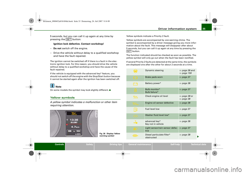
requiring attention.
Yellow symbols indicate a Priority 2 fault.
Yellow symbols are accompanied by one warning chime. The
symbol is accompanied by a driver message giving you more infor-
mation about the fault. This me ssage will disappear after about
5 seconds, but you can call it up again at any time by pressing the button.
The function indicated should be checked as soon as possible. The
yellow symbol will only go out when the fault has been rectified.
If several Priority 2 faults are detected at the same time, the symbols
are displayed one after the other for about 2 seconds at a time.
SET
Fig. 26 Display: Yellow
warning symbol
Dynamic steering
⇒ page 36 and
⇒ page 159
Brake pads worn
⇒page 37
Battery power*
⇒page 38
Bulb monitor*
Bulb failure*
⇒page 37
Check engine oil level
⇒page 38 or
⇒ page 38
Engine oil sensor defective
⇒page 38
Fuel level low
⇒page 37
Washer fluid level low*
⇒page 37
advanced key*
Key not in vehicle
⇒page 36
Light sensor/rain sensor defec-
tive
⇒page 37
Diesel particulate filter*
obstructed
⇒page 38
SET
document_0900452a81b1b9de.book Seite 35 Donnerstag, 26. Juli 2007 9:16 09
--4 -
-T
D
•
- +--
Page 39 of 342
Driver information system37
Controls
Safety
Driving tips
General maintenance
Self-help
Technical data
Light sensor / rain sensor defective
Automatic headlights / automatic wipers defective
If the symbol appears, this means that the light sensor / rain
sensor is not functioning.For safety reasons, the dipped beam head-
lights will then be switched on permanently when the light switch
is set to the AUTO position. However, you can still switch the lights
on and off in the normal way with th e light switch. If the rain sensor
is defective, the functions operated via the windscreen wiper lever
will still be available. You should have the light sensor / rain sensor
checked by a qualified workshop as soon as possible.
Brake pads worn
Brake pads!
If the symbol lights up, have the front brake pads (and, for
safety's sake the rear pads as well) inspected by a qualified
workshop.
Applies to vehicles: with bulb monitorBulb monitor
The bulb monitor checks whethe r the lights on the vehicle
are working.The bulb monitor checks whether the lights on the vehicle are
working. If it detects a defective bulb on the vehicle it will show a
yellow warning symbol together with a message indicating which
light is not working.
Bulb failure
If the symbol
lights up, this means that one of the turn signals
(front or rear), headlights, brake li ghts, rear lights, fog lights or the
rear fog light is not working.
WARNING
•
Bulbs are sensitive to pressure. The glass can break when you
touch the bulb, causing injury.
•
Incorrect handling of the high-voltage element of xenon gas-
discharge bulbs* can have potentially fatal consequences.Note
Have the components repaired or replaced by a qualified
workshop.Applies to vehicles: with washer fluid warning systemWasher fluid level low
Please top up washer fluid
If the symbol lights up, top up the fluid for the windscreen
washer and headlight washer system* ⇒page 267 .
Fuel level low
Please refuel
When this symbol
comes on for the first time, there are about
8 litres of fuel left in the tank. You should fill up as soon as possible
⇒ page 252 .
If this warning symbol lights up al though the fuel tank is sufficiently
filled, there is a malfunction in the fuel tank system. The display will
also show the driver message Tank system malfunction ! Contact
workshop . Please contact a qualified workshop.
document_0900452a81b1b9de.book Seite 37 Donnerstag, 26. Juli 2007 9:16 09
--4 -
-T
---- &
[I)
•
•
-+
•
•
+-
•
Page 63 of 342
Lights and vision61
Controls
Safety
Driving tips
General maintenance
Self-help
Technical data
Applies to vehicles: with xenon headlight bulbsDynamic headlight range controlHeadlights with xenon gas-discharge bulbs automatically adapt to
suit the load being carried when the engine is switched on. The
headlights are also automatically adjusted when the vehicle is in
motion (e.g. when accelerating and braking).Applies to vehicles: with adaptive lightadaptive light
This feature provides better illumination when you drive
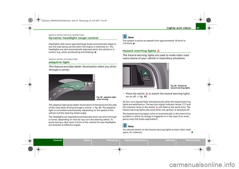
through a corner.The adaptive light gives better illumination of the bend and the side
of the road when driving through a corner ⇒fig. 59. The adaptive
light is controlled automatically, depending on the speed of the
vehicle and the steering wheel angle.
The headlights are regulated automatically when you drive through
a corner, depending on how far you turn the steering wheel. To
avoid having a dark spot in front of the vehicle the two headlights
are directed at different angles.
Note
The system is active at speeds from approximately 10 km/h to
110 km/h.Hazard warning lights
The hazard warning lights ar e used to make other road
users aware of your vehicle in hazardous situations.– Press the switch
to switch the hazard warning lights
on or off ⇒fig. 60.
All four turn signals flash simultaneously when the hazard warning
lights are switched on. The two turn signal indicator lamps
and
the indicator lamp in the switch
will flash at the same time. The
hazard warning lights also work when the ignition is switched off.
The hazard warning lights come on automatically in the event of an
accident in which an airbag is triggered or in the case of an emer-
gency stop (full br ake application).
Note
You should switch on the hazard warning lights to warn other road
users, for instance:
Fig. 59 adaptive light
when driving
Fig. 60 Switch for
hazard warning lights
document_0900452a81b1b9de.book Seite 61 Donnerstag, 26. Juli 2007 9:16 09
--4 -
-
[I]
T
•
•
-+ +-
[I]
Page 235 of 342
Towing a trailer233
Controls
Safety
Driving tips
General maintenance
Self-help
Technical data
additional mirrors fitted. Both exterior mirrors should be mounted
on hinged extension brackets. Adjust the mirrors to give sufficient
vision to the rear.
Headlights
Before starting a journey, check
the headlight beam settings with
the trailer hitched up. If necessary, alter the height of the headlight
beams by means of the headlight range control ⇒page 60 .
Power supply
When you remove the ignition key the power supply to the trailer is
interrupted.
Removable ball joint coupling
Vehicles with a factory-fitted towing bracket are equipped with a
removable ball joint coupling. It is carried under the floor panel on
the left-hand side of the luggage compartment and is secured by a
strap.
Note
We recommend having the car serviced between the normal inspec-
tion intervals if it used frequently for towing a trailer.Applies to vehicles: with towing bracketTrailer stabilisation system
Trailer stabilisation helps to reduce the risk of the vehicle
skidding when towing a trailer.The trailer stabilisation system is operational only when the ESP is
switched on and there is no malfunction in the ESP ⇒page 17 .
When is the trailer stab ilisation system activated?
Trailer stabilisation is active when the following requirements are
met:•
The ESP must NOT be switched off ⇒page 222 ,
•
The trailer connector must be properly secured in the vehicle
socket.
•
Vehicle speed must be higher than approx. 60 km/h.
How trailer stabilisation works:
In many cases, the driver can stabilise a swaying trailer by manually
braking the vehicle.
However, if the ESP detects that th e trailer is swaying and this is
affecting the towing vehicle, it will automatically brake the vehicle
to stabilise the trailer by slowing it down. The warning lamp
will
light up in the instrument cluste r. If possible, do not turn the
steering wheel at this stage.
In order to warn traffic behind you, the brake lights will come on
during this automatic braking operation.
A trailer weighing less than 70% of the kerb weight of the towing
vehicle may sway quite considerably without the trailer stabilisation
system intervening. This can happen when the swaying movements
of the light-weight trailer are not or hardly passed on to the towing
vehicle and are therefore not detected by the ESP.
If the system for activating the trai ler brake lights is defective, this
will be indicated in the instrument cluster display ⇒page 37, “Bulb
monitor ”.
Requirements for correct functioning of the trailer
stabilisation system
If these conditions are not met in full, the trailer stabilisation system
will only intervene to a limited extent or not at all ⇒.
•
The electrical connection between the towing vehicle and the
trailer must be functioning correctly, without any defects.
•
The load on the trailer must be properly secured.
•
The tyre pressures on both the vehicle and the trailer must be
adapted to the load that is being carried.
•
Where possible, operate the trai ler with the maximum permitted
draw bar weight.
document_0900452a81b1b9de.book Seite 233 Donnerstag, 26. Juli 2007 9:16 09
--4 -
-T
-+ [[
+-
•
Page 267 of 342
Checking and topping up fluids265
Controls
Safety
Driving tips
General maintenance
Self-help
Technical data
charges) when handling cables
and electrical equipment. Never
cross the battery poles. The re sulting high-energy sparks can
cause injury.
•
A highly explosive mixture of gases is given off when the
battery is under charge. Only char ge battery in a well ventilated
area.
•
Keep children away from the battery and battery acid.
•
Switch off all electrical equipment before starting any work on
the vehicle electrical system. Re move the ignition key. The minus
cable of the battery must be disc onnected. When changing a light
bulb, it is sufficient to only turn off the light.
•
Before disconnecting the battery, turn off the anti-theft
system! Otherwise, the alarm will sound.
•
When disconnecting th e battery from the vehicle's electrical
system, first disconnect the minu s cable and then the plus cable.
•
Before reconnecting the battery, turn off all electrical equip-
ment. First connect the plus cabl e, then the minus cable. The
battery cables must not be connected to the wrong battery poles
- serious risk of cable fire.
•
Never charge a frozen or thawed out battery - risk of explosion
and chemical burns! A battery must be replaced once it has been
frozen. When it is discharged th e battery can freeze at tempera-
tures around 0°C.
•
Make sure that the vapour hose is always attached to the
battery.
•
Never use a damaged battery - risk of explosion! Replace a
damaged battery immediately.Caution
•
Never disconnect the car's battery with the engine running or
with the ignition turned on, otherwise the electrical system or elec-
trical components will be damaged.
•
Do not expose the battery to direct sunlight over a long period of
time, as the intense ultraviolet radiation can affect the battery
housing.
•
If the car is left standing for long periods, protect the battery
from extreme cold temperature so that it does not “freeze up” and
become damaged.
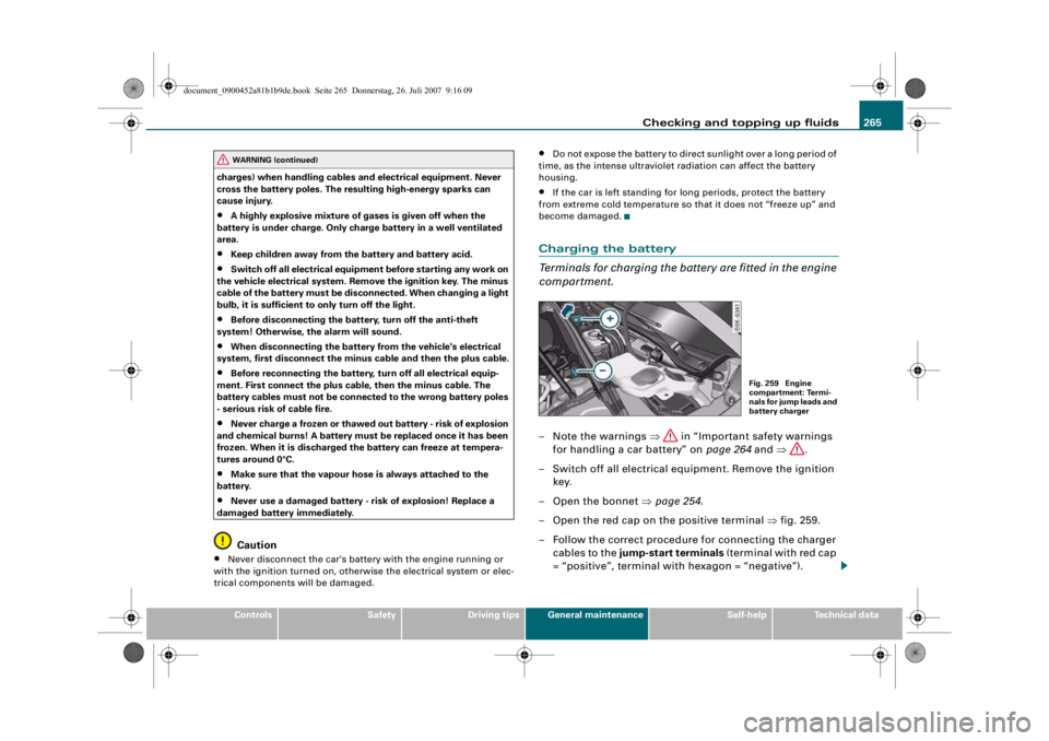
Charging the battery
Terminals for charging the battery are fitted in the engine
compartment.– Note the warnings ⇒ in “Important safety warnings
for handling a car battery” on page 264 and ⇒ .
– Switch off all electrical equi pment. Remove the ignition
key.
– Open the bonnet ⇒page 254 .
– Open the red cap on the positive terminal ⇒fig. 259.
– Follow the correct procedure for connecting the charger cables to the jump-start terminals (terminal with red cap
= “positive”, terminal with hexagon = “negative”).
WARNING (continued)
Fig. 259 Engine
compartment: Termi-
nals for jump leads and
battery charger
document_0900452a81b1b9de.book Seite 265 Donnerstag, 26. Juli 2007 9:16 09
--4 -
-T
•
-+ +-
CD
Page 286 of 342
Self-help
284If you need the tools, the Tyre Mobili ty System or the jack*, you will
have to open the floor panel and take out the spare wheel*
⇒ page 284 .
The tool kit includes:•
A hook for removing hub caps
•
Pin for mounting a wheel
•
Screwdriver with reversible blade
•
Tool for changing bulbs
•
Interchangeable socket (Torx socket for changing bulbs)
•
Crank handle for jack
•
Adapter for anti-theft wheel bolts*
•
Jack*
•
Box spanner for wheel bolts
•
Towline anchorage
Some of the parts listed are only fitted on certain models or are
optional extras.
Before stowing the jack* again, wind down the arm of the jack as far
as it will go.
WARNING
•
Do not use the hexagonal socket in the screwdriver handle to
tighten the wheel bolts. It is not po ssible to tighten the bolts with
the required torque – risk of accident.
•
The jack supplied by the factor y is only designed for changing
wheels on this model. On no account attempt to use it for lifting
heavier vehicles or other loads – risk of injury.
•
Never start the engine when the vehicle is on the jack - risk of
accident.
•
If work has to be done under the ve h i cl e , e n su re t h a t i t is sa fe l y
supported on stands designed for th e purpose, otherwise there is
a risk of injury.
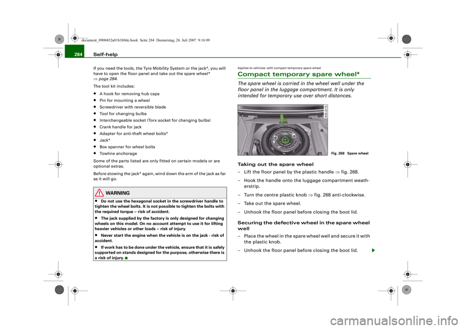
Applies to vehicles: with compact temporary spare wheelCompact temporary spare wheel*The spare wheel is carried in the wheel well under the
floor panel in the luggage compartment. It is only
intended for temporary use over short distances.Taking out the spare wheel
– Lift the floor panel by the plastic handle ⇒fig. 268.
– Hook the handle onto the luggage compartment weath- erstrip.
– Turn the centre plastic knob ⇒ fig. 268 anti-clockwise.
– Take out the spare wheel.
– Unhook the floor panel before closing the boot lid.
Securing the defective wheel in the spare wheel
well
– Place the wheel in the spare wheel well and secure it with the plastic knob.
– Unhook the floor panel before closing the boot lid.
Fig. 268 Spare wheel
document_0900452a81b1b9de.book Seite 284 Donnerstag, 26. Juli 2007 9:16 09
--4 -
-T
-+ +-
•
Page 302 of 342
Fuses and bulbs
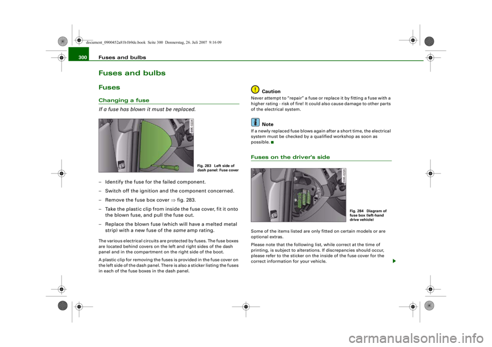
300Fuses and bulbsFusesChanging a fuse
If a fuse has blown it must be replaced.– Identify the fuse for the failed component.
– Switch off the ignition and the component concerned.
– Remove the fuse box cover ⇒fig. 283.
– Take the plastic clip from inside the fuse cover, fit it onto
the blown fuse, and pull the fuse out.
– Replace the blown fuse (which will have a melted metal strip) with a new fuse of the same amp rating.The various electrical circuits are protected by fuses. The fuse boxes
are located behind covers on the left and right sides of the dash
panel and in the compartment on the right side of the boot.
A plastic clip for removing the fuses is provided in the fuse cover on
the left side of the dash panel. There is also a sticker listing the fuses
in each of the fuse boxes in the dash panel.
Caution
Never attempt to “repair” a fuse or replace it by fitting a fuse with a
higher rating - risk of fire! It could also cause damage to other parts
of the electrical system.
Note
If a newly replaced fuse blows again after a short time, the electrical
system must be checked by a qualified workshop as soon as
possible.Fuses on the driver's sideSome of the items listed are only fitted on certain models or are
optional extras.
Please note that the following list, while correct at the time of
printing, is subject to alterations. If discrepancies should occur,
please refer to the sticker on the inside of the fuse cover for the
correct information for your vehicle.
Fig. 283 Left side of
dash panel: Fuse cover
Fig. 284 Diagram of
fuse box (left-hand
drive vehicle)
document_0900452a81b1b9de.book Seite 300 Donnerstag, 26. Juli 2007 9:16 09
--4 -
-T
CD
•
-+ +-
Page 303 of 342
Fuses and bulbs301
Controls
Safety
Driving tips
General maintenance
Self-help
Technical data
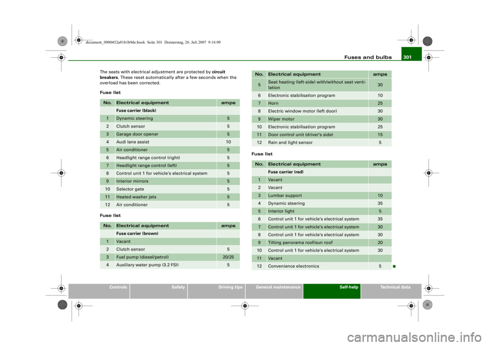
The seats with electrical adjustment are protected by circuit
breakers
. These reset automatically after a few seconds when the
overload has been corrected.
Fuse list
Fuse list Fuse list
No.
Electrical equipment
amps
Fuse carrier (black)
1
Dynamic steering
5
2
Clutch sensor
5
3
Garage door opener
5
4
Audi lane assist
10
5
Air conditioner
5
6
Headlight range control (right)
5
7
Headlight range control (left)
5
8
Control unit 1 for vehicle's electrical system
5
9
Interior mirrors
5
10
Selector gate
5
11
Heated washer jets
5
12
Air conditioner
5
No.
Electrical equipment
amps
Fuse carrier (brown)
1
Vacant
2
Clutch sensor
5
3
Fuel pump (diesel/petrol)
20/25
4
Auxiliary water pump (3.2 FSI)
5
5
Seat heating (left-side) with/without seat venti-
lation
30
6
Electronic stab
ilisation program
10
7
Horn
25
8
Electric window motor (left door)
30
9
Wiper motor
30
10
Electronic stabilisation program
25
11
Door control unit (driver's side)
15
12
Rain and light sensor
5
No.
Electrical equipment
amps
Fuse carrier (red)
1
Vacant
2
Vacant
3
Lumbar support
10
4
Dynamic steering
35
5
Interior light
5
6
Control unit 1 for vehicle's electrical system
35
7
Control unit 1 for vehicle's electrical system
30
8
Control unit 1 for vehicle's electrical system
30
9
Tilting panorama roof/sun roof
20
10
Control unit 1 for vehicle's electrical system
30
11
Vacant
12
Convenience electronics
5
No.
Electrical equipment
amps
document_0900452a81b1b9de.book Seite 301 Donnerstag, 26. Juli 2007 9:16 09
--4 -
-T
1111
-
-
1111
--
1111
-
-
1111
-
-+
1111
--
+-
1111
--
1111
--
-
1111
-
-
1111
--
1111
--
•
~
Page 304 of 342
Fuses and bulbs
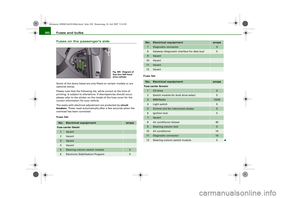
302Fuses on the passenger's sideSome of the items listed are only fitted on certain models or are
optional extras.
Please note that the following li st, while correct at the time of
printing, is subject to alterations. If discrepancies should occur,
please refer to the sticker on the inside of the fuse cover for the
correct information for your vehicle.
The seats with electrical adjustment are protected by circuit
breakers . These reset automatically after a few seconds when the
overload has been corrected.
Fuse list Fuse listNo.
Electrical equipment
amps
Fuse carrier (black)1
Vacant
2
Vacant
3
Vacant
4
Vacant
5
Steering column switch module
5
6
Electronic Stabilisation Program
5
Fig. 285 Diagram of
fuse box (left-hand
drive vehicle)
7
Diagnostic connector
5
8
Gateway (diagnostic in
terface for data bus)
5
9
Vacant
10
Vacant
11
Vacant
12
Vacant
No.
Electrical equipment
amps
Fuse carrier (brown)1
CD drive
5
2
Switch module for Audi drive select
5
3
MMI/Radio
10/20
4
Light switch
5
5
Control unit for instrument cluster
5
6
Ignition lock
5
7
Vacant
8
Air conditioner blower
40
9
Steering column lock
5
10
Air conditioner
10
11
Diagnostic connector
10
12
Steering column switch module
5
No.
Electrical equipment
amps
document_0900452a81b1b9de.book Seite 302 Donnerstag, 26. Juli 2007 9:16 09
-+ ~
--11-
..
-
..
-
..
-
..
-
..
..
..
..
..
..
..
..
..
..
..
--4 -
-
-
T
-
-
-
-
-
+-
-
-
-
-
-
•
4-
---r