technical data AUDI S4 CABRIOLET 2009 User Guide
[x] Cancel search | Manufacturer: AUDI, Model Year: 2009, Model line: S4 CABRIOLET, Model: AUDI S4 CABRIOLET 2009Pages: 340, PDF Size: 77.32 MB
Page 55 of 340
Doors, power locks
Operating locks vvith the key
To lock and unlock the vehicle from the outside, turn the
key in the lock of the driver's door.
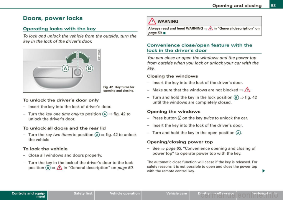
To unlock the driver's door only
Fig . 42 Key turns for
opening and closing.
- Insert the key into the lock of driver's door.
- Turn the key
one time only to pos ition @=>fig. 42 to
unlock the driver's door .
To unlock all doors and the rear lid Turn the key
two times to pos ition @=> fig. 42 to unlock
the veh icle
To lock the vehicle - Close all windows and doors properly.
- Turn the key in the lock of the driver's door to the lock position
@ ~ & in "General descript ion" on page 50.
Contro ls and eq uip
ment
Opening and closing
& WARNING
Always read and heed WARNING~ & in "General description" on
page 50. •
Convenience close /open feature vvith the
lock in the driver 's door
You can close or open the windows and the power top
from outside when you lock or unlock your car with the
key.
Closing the windows
- Insert the key into the lock of the driver's door.
- Make sure that the windows are not blocked~& .
- Turn and hold the key in the lock position @=>fig. 42
until the w indows are completely closed.
Opening the windows
- Press button @ on the key
twice to unlock the car.
- Insert the key into the lock of the driver's door .
- Turn and hold the key in the open position @.
Opening/closing power top
- See =>
page 63, "Convenience opening and closing of
power top" to operate power top with the key.
The automatic close function will cease if the key is released. For
safety reasons it is not possible to open and close the power top
with the remote control key . ..,
~ehicle care Technical data
Page 61 of 340
Power windows
Controls
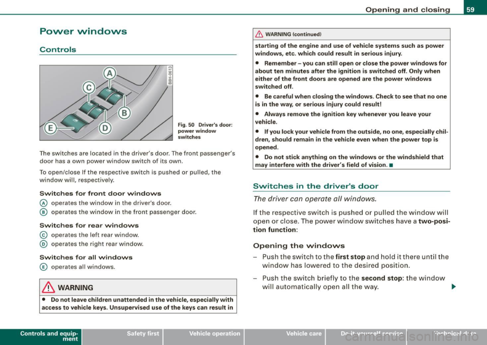
Fig. 50 Driver's door:
power window
switches
The switches are located in the driver's door. The front passenger's
door has a own power window switch of its own.
To open/close If the respective switch is pushed or pulled, the
window will, respectively .
Switches for front door windows
© operates the window in the driver's door.
@ operates the window in the front passenger door.
Switches for rear windows
© operates the left rear window.
@ operates the right rear window.
Switches for all windows
© operates all windows .
& WARNING
• Do not leave children unattended in the vehicle, especially with
access to vehicle keys. Unsupervised use of the keys can result in
Contro ls and eq uip
ment
Opening and closing
& WARNING (continued)
starting of the engine and use of vehicle systems such as power
windows, etc. which could result in serious injury.
• Remember -you can still open or close the power windows for
about ten minutes after the ignition is switched off. Only when
either of the front doors are opened are the power windows
switched off.
• Be careful when closing the windows . Check to see that no one
is in the way, or serious injury could result!
• Always remove the ignition key whenever you leave your
vehicle.
• If you lock your vehicle from the outside, no one, especially
chil
dren, should remain in the vehicle even when the power top is
opened.
• Do not stick anything on the windows or the windshield that
may interfere with the driver's field of vision. •
Switches in the driver's door
The driver can operate all windows.
If the respect ive switch is pushed or pulled the windo w will
open or close . The power w indow switches have a
two-posi
tion function:
Opening the windows
Push the switch to the first stop and hold it there until the
window has lowered to the desired position.
Push the switch briefly to the
second stop: the window
will automatically open all the way. ..
~ehicle care Technical data
Page 67 of 340
Power top: ca nnot b e use d
Power top not operating
This message wi ll appear in the display if the power top has been
deactivated for safety reasons or if there is a malfunction. Possible
causes are:
• vehicle speed t oo high: the power top operation is deactivated
for safety reasons if the vehic le is mov ing at a speed above 3 mph
(5 km/hi.
• battery voltage too low: the power top wil l not operate if the
battery voltage is too low . This is a precautionary feature to make
s u re that the re is always enough battery power avai lable to start the
engine. The power top can be activated again once the engine has
been started and is running.
• ove rload cut -off: if the power top is operated repeatedly the
hydraulic actuator components will be severely stressed . In this
case the over load cut -off will safeguard the system against damage.
This safeguard deactiva tes the system fo r abou t 15 to 30 minutes.
After this time the power top can be operated again as usual=> & .
• Malfunction: One possible cause of a malfunction is the fai lure
of a system component. In this case the power top can a lso be
manual ly operated =>
page 68. Turning off the ignition during the
opening or closing process may cause a malfunction. You can
correct this yourself=>
page 65.
Pow er top no t sec ure
Power top not locked in place
If the top has not opened or closed completely and the vehicle
moves then at a speed above 3 mph (5 km/h), this
warning will
appear in the instrument cluster display. Stop the vehicle. Open or
close the power top completely. The warning should disappear .
& WARNING
Never drive the car with a power top that is not securely lock ed in
place . If it i s not fir mly engaged , the top can b e blown ope n by the
Contro ls and eq uip
ment
P o w er top
& W ARN ING (conti nued )
airstre am and ca u se injur ies and damage to the vehicle . - Risk of
crash !•
Correcting a malfunction
Turning off the ignition durin g the opening or closing
process may cause a malfunction.
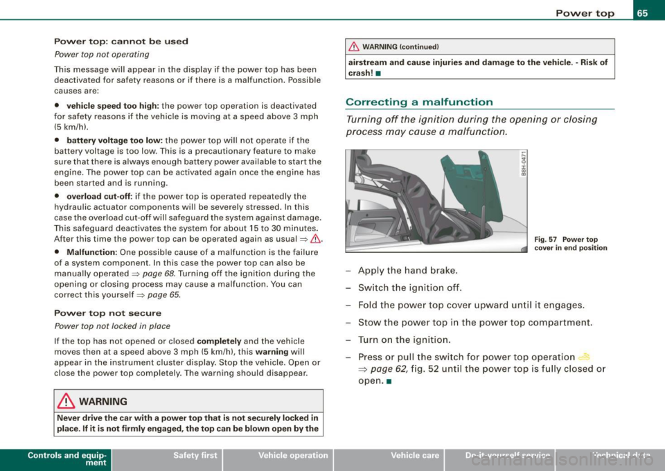
F ig. 57 Power top
cov er in end p osition
App ly the hand b rake.
Sw it c h t he igniti on off .
Fold the powe r top cove r upward un til it engages.
Stow the power top in the powe r top compa rtment.
T ur n on the igni tion.
Press or pull the swi tch f or p ow er top operatio n
~ page 62, fig . 52 un til the powe r top is f ully clos ed o r
open .a
~ehicle care Technical data
Page 71 of 340
forward goes much easier when done by two people. However, if no
assistance is available, you may find it easier to position yourself on
the rear seatbench and lift the power top up by grabbing it at the
center. •
Where is the manual release key stored?
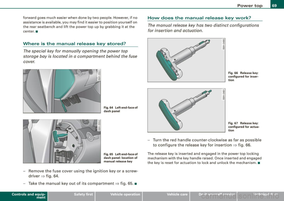
The special key for manually opening the power top
storage bay is located in a compartment behind the fuse
cover.
Fig. 64 Left end-face of
dash panel
Fig. 65 Left end-face of
dash panel: location of
manual release key
-Remove the fuse cover using the ignition key or a screw
driver=:> fig. 64.
- Take the manual key out of its compartment=:> fig. 65. •
Controls and eq uip
ment
Power top
How does the manual release key work?
The manual release key has two distinct configurations
for insertion and actuation.
g
9 :c: ., a,
j ., m
Fig . 66 Release key:
configured for inser
tion
Fig. 67 Release key:
configured for actua
tion
Turn the red handle counter-clockwise as far as poss ible
to configure the release key for insertion =:> fig. 66.
The release key is inserted and engaged in the power top locking
mechanism with the key handle raised. Once inserted and engaged
the key is reset for actuation to lock and unlock the mechanism. •
~ehicle care Technical data
Page 77 of 340
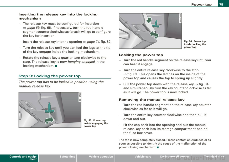
Inse rting the r ele ase ke y i nto th e lock ing
me ch ani sm
- The release key must be configured for insertion
:::;, page 69, fig. 66. If necessary, turn the red hand le
segment counterclockw ise as far as it will go to configure
the key for insertion.
- Insert the release key into the opening:::;,
page 74, fig. 82.
- Turn the release key until you can feel the lugs at the tip of the key engage ins ide the locking mechanism .
- Rotate the release key a quarter turn c lockwise to the
stop. The release key is now
hanging engaged in t he
locking mechanism .•
Step 9: Locking the power top
T he power top has to be locked in position using the
manual release key.
Contro ls and eq uip
ment
Fi g. 83 Po w er top
i nsi de: engagi ng t he
p owe r to p
Locking th e pow er t op P
o w er top
Fig . 84 Powe r to p
in side: l ocki ng the
powe r to p
- Turn the red handle segment on the release key until you
can hear it engage.
- Turn the entire re lease key clockw ise to the stop
:::;, fig. 83 . This opens the latc hes on the ins ide of the
power top and causes the top to spring up s lightly.
- Pu ll the power top down with the release key:::;, fig. 84
and simultaneously turn the key counter -clockwise as far
as it will go. The power top is now locked.
Remo ving the manual release key
- Turn the red handle segme nt on the release key counter
clockwise as far as it wi ll go.
- Turn the entire key counter-clockw ise and t hen pull it
down and out.
- Fit the cap back into t he opening and p ut the manual
release key back into its storage compartment behind
the fuse box cover .
The top is now completely closed. Please contact an Audi dealer as
soon as possible to identify the cause of the malfunction of the
power c los ing mechanism. •
~ehicle care Technical data
Page 83 of 340
[ i J Tip s
• Do not attach any stickers to the windshield in front of the two
light sensors, as this would interfere with both the automatic oper
ation of the head ligh ts and the automatic dimming of the inside
mirror(s).
• If the veh icle is remotely un locked and locked
three times in
succession,
leaving home will not turn on the lights a fourth time to
safeguard the battery and lights.
• If you wish to use the coming home/leaving home function regu
larly, you can leave it activated at all times wi thout risking perma
nent strain on the electrical system. As the system is contro lled by
light sensors, i t wi ll only b e energi zed in darkness.
• Frequent use of the coming home/leaving home function for
approac hin g and departing a vehicle parked in the dark wi ll strain
the batte ry. This applies particularly if only short distances are
driven between stops . Occasiona lly drive longer distances to make
sure the battery is recharged sufficient ly.
• If the fo g lights have been switched on by the coming
home/leaving home function, they will always be switched off when
you switch on the ig nition. •
Contro ls and eq uip
ment
Cle ar v ision
Instrument panel illumination
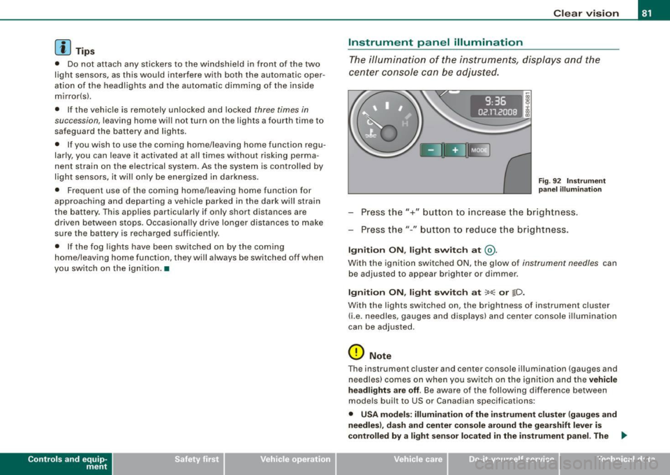
The ill umina tion of the ins trume nts, dis pla ys and the
cente r consol e can be adjusted.
9:3 6
02.11.2008
Fig . 9 2 Instru men t
pane l illum in a ti on
Press the"+" button to increase the brigh tness .
Press the" -" b utton to reduce the br ig htness.
Igniti on ON , light swit ch at @ .
With the ignition switched ON, the glow of instrument needles can
be adjusted to appear brighter or dimmer.
Ignition ON , light switch at :oo: or gD.
With the lights switched on, the brightness of instrument cluster
(i .e. needles, gauges and displays) and center c onsole il luminat io n
can be adjusted .
0 Note
The instrument c luster and center console i llumination ( gauges and
needles) comes on when you swi tch on the ignition and the
vehicle
headlights are off .
Be aware of the following difference between
models built to US or Canadian specifications:
• USA model s: illumination of the in strument cluster (gauge s and
needles ), dash and center conso le around the gearshift lever is
controlled
by a light sen sor located in the instrument panel. The .,
~ehicle care Technical data
Page 91 of 340
& WARNING
The glass of the inside rearview mirror is layered and contains an
electrolyte to achieve its properties. Be aware of liquid electrolyte
leaking from a broken mirror glass. This liquid can cause irritation
to skin, eyes, and respiratory system. If you get electrolyte in your
eyes or on your skin, immediately rinse with plenty of water. If irri
tation persists, seek medical attention.
0 Note
Liquid electrolyte leaked from a broken mirror glass will damage any
plastic surfaces it comes in contact with. Clean up spilled electrolyte
immediately with clear water and a sponge.
[ i] Tips
• If you switch off the automatic dimming function on the inside
mirror, automatic dimming of the outside mirrors will likewise be
disabled.
• Check to make sure there are no objects preventing light from
reaching the inside mirror.
• Do not attach any stickers to the windshield in front of the light
sensor, as this would interfere with the automatic operation of the
headlights and the automatic dimming of the inside mirror.•
Controls and eq uip
ment
Clear vision
Outside mirrors
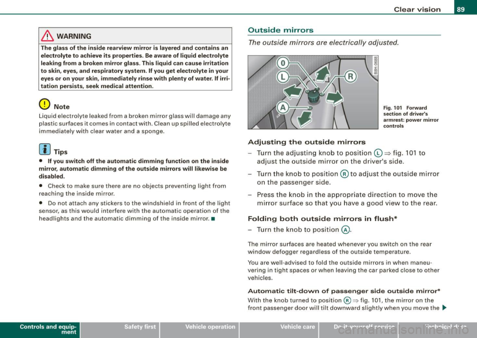
The outside mirrors are electrically adjusted.
Adjusting the outside mirrors
Fig. 101 Forward
section of driver's
armrest: power mirror
controls
Turn the adjusting knob to position (D => fig. 101 to
adjust the outside mirror on the driver's side.
Turn the knob to position
@ to adjust the outside mirror
on the passenger side.
Press the knob in the appropriate direction to move the
mirror surface so that you have a good view to the rear.
Folding both outside mirrors in flush*
- Turn the knob to position @.
The mirror surfaces are heated whenever you switch on the rear
window defogger regardless of the outside temperature.
You are well -advised to fold the outside mirrors in when maneu
vering in tight spaces or when leaving the car parked close to other
vehicles.
Automatic tilt-down of passenger side outside mirror*
With the knob turned to position@:::::, fig. 101, the mirror on the
front passenger door will tilt downward slightly when you move the .,_
~ehicle care Technical data
Page 111 of 340
__________________________________________________ S_ e_ a_t _s _ a_n _ d_ s_ t _ o_ r_a ...;:g ::.. e _ ___,ffllll
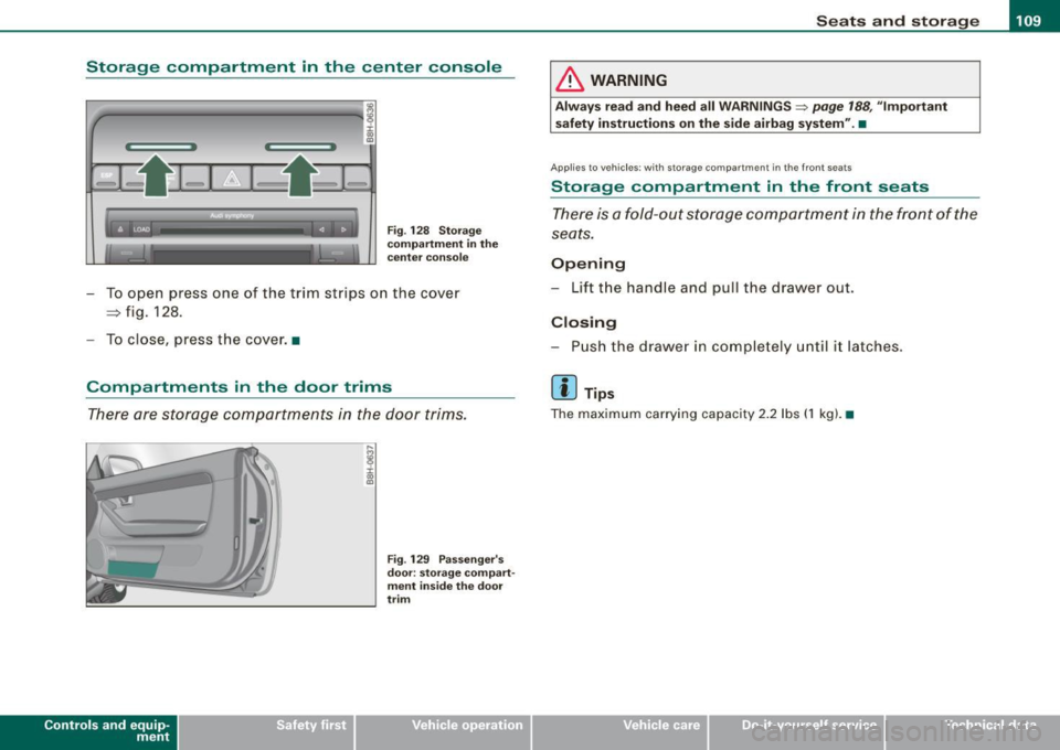
Storage compartment in the center console
,,,_ _______________ ..,. ,
:c
ll:
Fig . 128 Storage
compartment in the
center console
To open press one of the trim str ips on the cover
=> fig. 128.
To close, press the cover. •
Compartments in the door trims
There are storage compartments in the door trims .
Controls and eq uip
ment
Fig . 129 Passenger 's
door : storage compart
ment inside the door
trim
& WARNING
Always read and heed all WARNINGS~ page 188, ulmportant
safety instructions on the side airbag system".•
Applie s to veh ic le s: w ith storage c om part me nt in the fr ont seats
Storage compartment in the front seats
There is a fold-out storage compartment in the front of the
seats.
Opening
- Lift the handle and pull the drawer out .
Closing
-Push the drawer in completely until it latches.
[ i] Tips
The maximum carrying capacity 2.2 lbs (1 kg). •
~ehicle care Technical data
Page 123 of 340
On the road -_______________ ____,
0 Note
Do not stop the engine immediately after hard or extended driving.
Keep the engine running for approximately two minutes to prevent
excessive heat build-up. •
Parking brake
Parking brake
When the parking brake is set, it prevents the vehicle from
rolling away unintentionally.
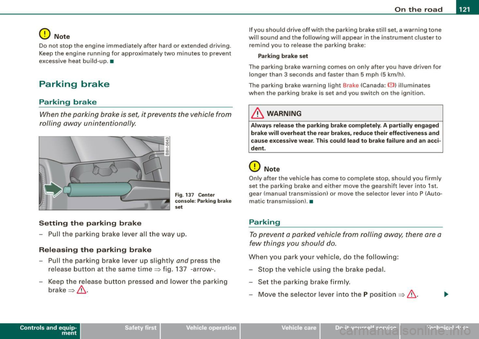
Setting the parking brake
Fig . 137 Center
console: Parking brake
set
- Pull the parking brake lever all the way up.
Releasing the parking brake
- Pull the parking brake lever up slightly
and press the
release button at the same time=:> fig. 137 -arrow-.
- Keep the release button pressed and lower the parking
brake =>
&-
Contro ls and eq uip
ment
If you should drive off with the parking brake still set, a warning tone
will sound and the following will appear in the instrument cluster to
remind you to release the parking brake:
Parking brake set
The parking brake warning comes on only after you have driven for longer than 3 seconds and faster than 5 mph (5 km/h).
The parking brake warning light Brake (Canada:
{(j))) illuminates
when the parking brake is set and you switch on the ignition .
& WARNING
Always release the parking brake completely. A partially engaged
brake will overheat the rear brakes, reduce their effectiveness and
cause excessive wear. This could lead to brake failure and an acci
dent.
0 Note
Only after the vehicle has come to complete stop, should you firmly
set the parking brake and either move the gearshift lever into 1st.
gear (manual transmission) or move the selector lever into P (Auto
matic transmission). •
Parking
To prevent a parked vehicle from rolling away, there are a
few things you should do.
When you park your vehicle, do the following:
- Stop the vehicle using the brake pedal.
- Set the parking brake firmly.
- Move the selector lever into the
P position =:> &.
~ehicle care Technical data
Page 133 of 340
Transmi ssio n -_______________ ___,
[ i J Tip s
• When you shi ft into the next lower gear, the transmission wi ll
downshi ft only when there is no poss ibi lity of over -rew ing the
engine.
• When the kick -down com es on, the transmission will shift down
to a lower gear, depending on vehicle and engine speeds .
• The tiptronic® is inoperative when the transmission is in the fail
sa fe mode .•
A pplies to vehicles : wit h 6-s pee d aut om ati c tra nsm is si on
Steering wheel with tiptronic ®
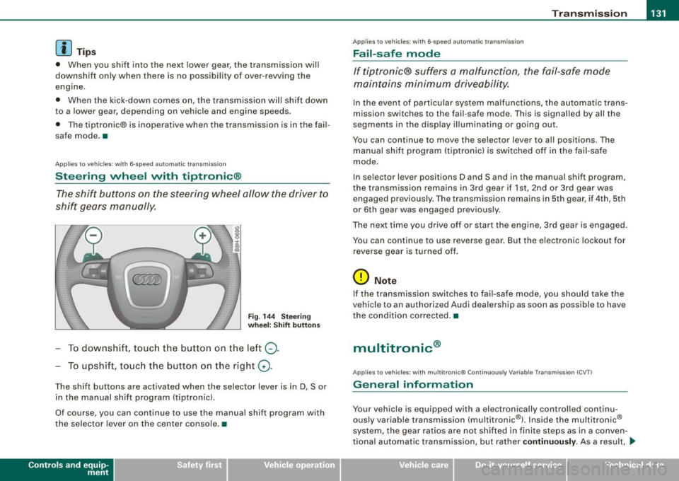
The shift buttons on the steering wheel allow the driver to
shift gears manually.
F ig . 14 4 Steer ing
w heel: Shi ft button s
-To downshif t, touch the button on the left Q .
To upshift, touch the button on the right G) .
The shift buttons are activated when the selector lever is in D, Sor
in the manual shift program (tiptronic).
Of course, you can continue to use the manual shift program with
the selector lever on the center console .•
Contro ls and eq uip
ment
A pp lies to vehicles: w ith 6-speed automat ic tra nsmission
Fail -safe mode
If tiptronic® suffers a malfunction, the fail-safe mode
maintains minimum drive ability .
In the event of particular system malfunct ions, the automatic trans
m ission switches to th e fail -saf e mode. This is signalled by all the
seg ments in the display illuminating or going out .
You can continue to move the selec tor lever to all positions . The
manual shift program (tiptronic) is switched off in the fail -safe
mode .
In selector lever posi tions D and Sand in the manual shift program,
the transmission remains in 3rd gear if 1st, 2nd or 3rd gear was engaged previous ly. The transmission remains in 5th g ear, if 4th , 5th
or 6 th gear was engaged previous ly .
The next time you drive off o r start the engine , 3rd gear is engaged .
You can continu e to use reverse gear . But the electron ic lockout for
reverse gear is turned off.
0 Note
If the transmission sw itches to fail -sa fe mo de, you should take the
vehicle to an authori zed Audi dea le rship as soon as possib le to have
the condition corrected .•
multitronic ®
Applies t o vehic les: w it h mu lt itr on ic® Co nti nuous ly V aria ble Trans mission (CVT )
General information
Your vehicle is equipped with a electron ically controlled continu
ously variable transmission (mult itronic ®l. Inside the multitronic ®
system, the gear ratios are not shifted in finite steps as in a conven
tional automatic transm ission, but rath er
contin uousl y. As a result, ...
~ehicle care Technical data