AUDI S6 2009 Owners Manual
Manufacturer: AUDI, Model Year: 2009, Model line: S6, Model: AUDI S6 2009Pages: 398, PDF Size: 43 MB
Page 361 of 398
________________________________________________ E _m_ e_r.:g :;,. e_ n_c ...: y:.- s_ i_ t _u _a_ t_ i_ o _ n_ s __ ffllll
•
Conn ect POSITIVE (+ ) to PO SITIVE (+ ) (r ed )
- Open the red cover on the pos itive pole => page 358,
fig. 270.
1. Connect one end of the positive cable (red) on the
jump
start bolt=>
page 358, fig. 27 1 G) (Bolts under red cover
= "positive") of the vehicle to be started @.
2. Connect the other end to the positive terminal@ of the
booster battery ®·
Conn ect NEGATIVE (- ) to NEGATIVE (-) (black )
3. Connect one end to the negat ive termi nal 0 of t he
boos ter battery ®·
4 . Connect the other end of the negative cable (black) to the
jump sta rt bolt 0 (Bolts with hex head = "n egative") of
the vehicle to be s tarted @.
Startin g th e e ngin e
-Start the engine of the veh icle w ith the booster battery .
Run t he engine at a moderate speed .
- Start engine with discharged ve hicle battery in the usual
ma nner.
- If the engine fails to s tart: do not keep the star ter
cranking for longer than 10 seconds. Wait f or about
30 seconds and then try again.
- With engine running, remove jumper cables from both
vehicles in the exact reverse order.
- Close the red cover on the positive pole.
The battery is vented to the outside to prevent gases from entering
the vehic le interior . Make sure that the jumper clamps are well connected with their
metal parts in full contact with the battery
t erminals .
& WARNING
To avoid seriou s per sonal in jur y a nd d amage to the vehicle , heed
a ll wa rning s and in stru ction s o f th e jum per ca ble man ufa cturer . If
in doubt , call for ro ad serv ice.
• Jump er c able s must b e lo ng eno ugh so that the vehi cle s d o not
touch .
• When conne cting jumpe r cable s, ma ke sure th at the y cann ot
g et caught in an y mo ving p arts i n the engine comp art m ent .
• Before you che ck anyth ing in the en gin e com partm ent , a lwa ys
r ea d and h eed all W ARNIN GS~ pag e 293, "E ngine compa rtm ent ".
0 Note
Improper hook -up of jumper cables can ruin the generato r.
• Always connect POSITIVE(+) to POS ITIVE( +), and NEGATIVE( -) to
NEGATIVE( -) ground post of the battery manager control unit.
• Check that al l screw p lugs on the battery ce lls are screwed in
firm ly . If not, tighten plugs prior to connecting clamp on negative
battery termi nal.
• Please note that the procedure for connecting a jumper cab le as
described above applies specifical ly to the case of your vehicle
being jump started. When you are giving a jump start to another
vehicle, do
not connect the negative(-) cable to the negative (-1
terminal on the discharged battery©~
page 358, fig. 271. Instead,
securely connect the negative ( -1 cable to either a solid metal
component that is firmly bolted to the engine b lock or to the engine
block itself . If the battery that is being charged does not vent to the
outside, escap ing battery gas could ignite and exp lode! •
Do-it-yourself service
Page 362 of 398
lll'I...__E_ m _ e _r.;:g '-e_ n_ c-=y _ s_ i_t _u _a _t_ i_o _n_ s _______________________________________________ _
Emergency towing with commercial
tow truck
General hints
Your Audi requires special handling for towing.
The following information is to be used by commercial tow truck
operators who know how to operate their equipment safely.
• Never tow your Audi, towing will cause damage to the engine
and transmission.
• Never wrap the safety chains or winch cables around the brake
lines.
• To prevent unnecessary damage, your Audi must be transported
with a flat bed truck.
• To load the vehicle on to the flat bed, use the towing loop found
in the vehicle tools and attach to the front or rear anchorage
~ page 360 and~ page 361.
& WARNING
A vehicle being towed is not safe for passengers. Never allow
anyone to ride in a vehicle being towed, for any reason. •
Front towing loop
Do not install the front towing loop until it is needed.
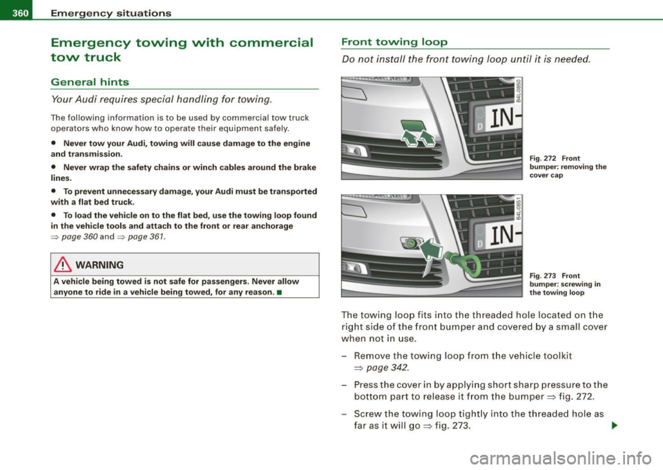
Fig. 272 Front
bumper: removing the
cover cap
Fig . 273 Front
bumper: screwing in
the towing loop
The towing loop fits into the threaded hole located on the
right side of the front bumper and covered by a small cover
when not in use.
- Remove the towing loop from the vehicle toolkit
=>
page 342.
- Press the cover in by applying short sharp pressure to the
bottom part to release it from the bumper => fig. 272.
- Screw the towing loop tightly into the threaded hole as
far as it will go=> fig. 273. ..,
Page 363 of 398
________________________________________________ E_ m_ e_r ,,::g c..e_ n _ c..::y;._ s_ i_t _u _a_ t_ i_o _n_ s _ ___._
When it is no longer needed, unscrew the towing loop and put it
back into the vehicle toolkit. Be sure to have the towing loop stored
in the vehicle at all times.
& WARNING
If the towing loop is not screwed in as far as it will go, the thread
can pull out when the vehicle is towed -potential risk of an
accident. •
Rear towing loop
Do not install the rear towing loop until it is needed.
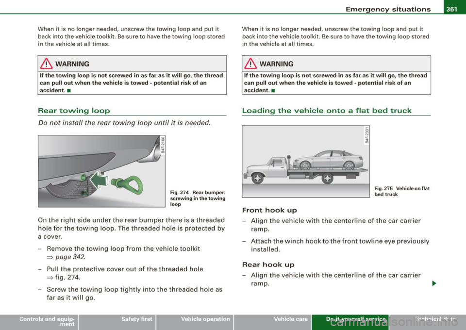
Fig. 274 Rear bumper:
screwing in the towing
loop
On the right side under the rear bumper there is a threaded
hole for the towing loop. The threaded hole is protected by
a cover.
- Remove the towing loop from the vehicle toolkit
=> page 342.
- Pull the protective cover out of the threaded hole
~ fig. 274 .
- Screw the towing loop tightly into the threaded hole as far as it will go .
When it is no longer needed, unscrew the towing loop and put it
back into the vehicle toolkit. Be sure to have the towing loop stored
in the vehicle at all times.
& WARNING
If the towing loop is not screwed in as far as it will go, the thread
can pull out when the vehicle is towed -potential risk of an
accident. •
Loading the vehicle onto a f lat bed truck
Front hook up
Fig . 275 Vehicle on flat
bed truck
- Align the vehicle with the centerline of the car carrier
ramp.
- Attach the winch hook to the front towline eye previously
installed .
Rear hook up
-Align the vehicle with the centerline of the car carrier
ramp.
Vehicle care Do-it-yourself service irechnical data
Page 364 of 398
lll'I...__E_ m _ e _r.;:g '-e_ n_ c-=y _ s_ i_t _u _a _t_ i_o _n_ s _______________________________________________ _
- Attach the winch hook to the rear towline eye previously
installed.
[ i ) Tips
Check carefully to make sure the hook -up is secure before moving
the ca r up the flatbed t ruck ramp. •
Lifting vehicle
Lifting with workshop hoist and with floor
jack
The vehicle may only be lifted at the lifting points illus
trated.
~ ~
\ ======== ======= ~ ;,
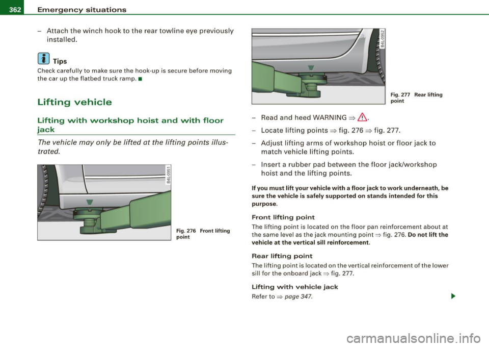
Fig. 276 Front lifting
point
- Read and heed WARNING::::,& .
Fig. 277 Rear lifting
point
-Locate lifting points::::, fig. 276 ::::, fig. 277.
- Adjust lifting arms of workshop hoist or floor jack to
match vehicle lifting points.
- Insert a rubber pad between the floor jack/workshop
hoist and the lifting points.
If you must lift your vehicle with a floor jack to work underneath, be
sure the vehicle is safely supported on stands intended for this
purpose.
Front lifting point
The lifting point is located on the floor pan reinforcement about at
the same level as the jack mounting point:::::, fig. 276 .
Do not lift the
vehicle at the vertical sill reinforcement.
Rear lifting point
The lifting point is located on the vertical reinforcement of the lower
sill for the on board jack:::::, fig. 277.
Lifting with vehicle jack
Refer to :::::, page 347 .
Page 365 of 398
________________________________________________ E _m_ e_r.:g :;,. e_ n_c ...: y:.- s_ i_ t _u _a_ t_ i_ o _ n_ s __ lllll
•
& WARNING
• To reduce the risk of serious injury and vehicle damage.
-Always lift the vehicle only at the special workshop hoist and
floor jack lift points illustrated
=> page 362, fig. 276 and
=> page 362, fig. 277.
- Failure to lift the vehicle at these points could cause the
vehicle to tilt or fall from a lift if there is a change in vehicle
weight distribution and balance. This might happen, for
example, when heavy components such as the engine block or
transmission are removed.
• When removing heavy components like these, anchor vehicle
to hoist or add corresponding weights to maintain the center of
gravity. Otherwise, the vehicle might tilt or slip off the hoist,
causing serious personal injury.
0 Note
• Be aware of the following points before lifting the vehicle:
- The vehicle should never be lifted or jacked up from under
neath the engine oil pan, the transmission housing, the front or
rear axle or the body side members . This could lead to serious
damage.
- To avoid damage to the underbody or chassis frame, a rubber
pad must be inserted between the floor jack and the lift points.
- Before driving over a workshop hoist, check that the vehicle
weight does not exceed the permissible lifting capacity of the hoist .
- Before driving over a workshop hoist, ensure that there is
sufficient clearance between the hoist and low parts of the
vehicle. •
Do-it-yourself service
Page 366 of 398

_,
Page 367 of 398

~
.> -
\\
o:i,
o.0. \'?> ...........
... ~ 'A
Page 368 of 398
111!1....__G_ e_ n_ e_r_a _ l_ i _n_ f_ o_ rm_ a _t_io _ n _______________________________________________ _
General information
Explanation of technical data
Some of the technical data listed in this manual requires
further explanation.
The technical data for your vehicle is listed in the charts starting on
~ page 369 . This section provides general information, notes and
restrictions which app ly to this data. •
Vehicle identification
The key data is given on the vehicle identification number
(VIN) pla te and the vehicle data st icker.
F ig. 278 Ve hicl e Id enti
fi ca tion Number (V IN)
pl ate : lo cation on
d riv er 's s ide das h
pan el F
ig . 2 79 The vehi cle
i d e ntifi cat ion la be l -
i nside the lug gag e
com partm ent
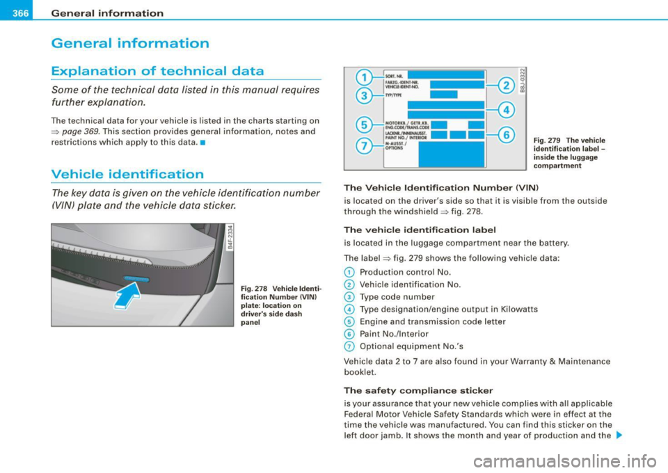
The Vehicle Id enti fication Numb er (V IN)
is located on the driver's side so that it is visible from the outside
through the windshield ~ fig . 278.
Th e veh icle i de ntifi cat ion lab el
is located in the luggage compar tment near the battery.
The label~ fig. 279 shows the following vehic le data :
0 Production control No.
0 Vehicle identification No.
G) Type code number
© Type designation/engine output in Ki lowatts
@ Engine and transmission code letter
© Paint No./lnterior
0 Optiona l equipment No.'s
Vehicle data 2 to 7 are also found in your Warranty
& Maintenance
booklet.
Th e s afet y co mpli ance sti cker
is your assurance that your new vehicle complies with a ll app licable
Federa l Motor Vehicle Safety Standards which were in effect at the
time the vehicle was manu factured. You can find this sticker on the
left door jamb . It shows the month and year of production and the .._
Page 369 of 398
_________________________________________________ G_ e_ n_ e_r _a _l_ i_n _f_o _ r_ m_ a_ t _i _o _ n __ PII
vehicle identification number of your vehicle (perforation) as well as
the Gross Vehicle Weight Rating (GVWR) and the Gross Axle Weight
Rating (GAWRl.
The high voltage warning label is located on the lock carrier.
The spark ignition system complies with the Canadian standard ICES-002. •
Displaying Vehicle Identification
Number in the MMI
Fig. 280 MMI display:
Vehicle ID number
(VIN)
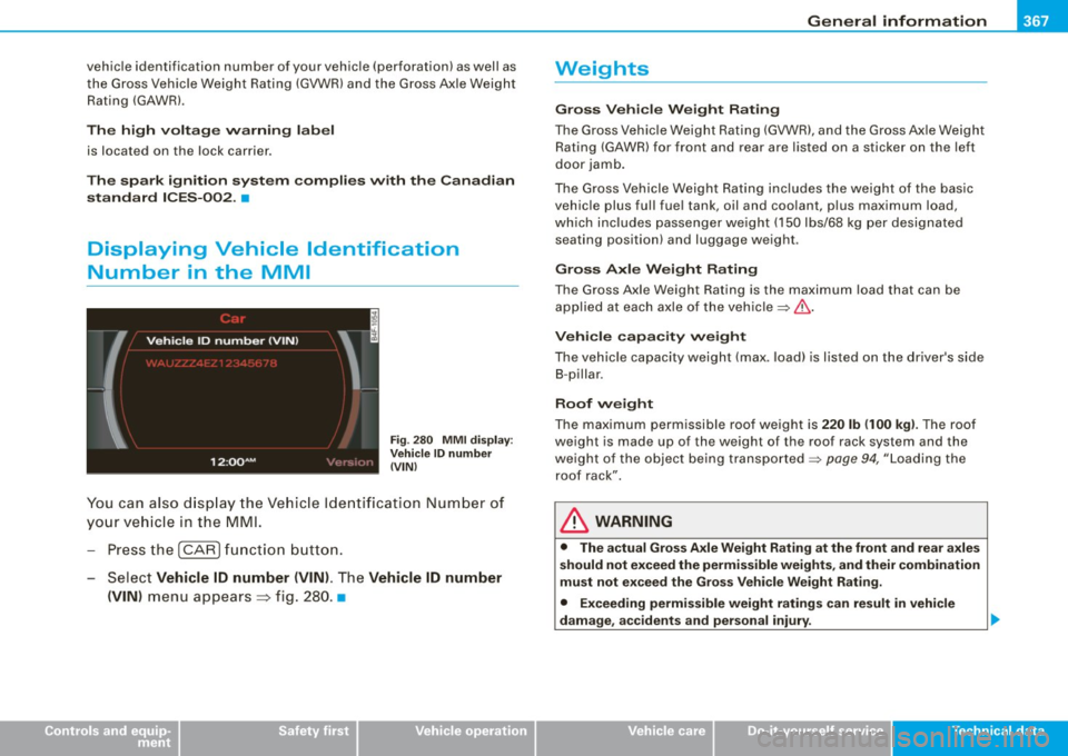
You can also display the Vehicle Identification Number of
your vehicle in the MMI.
- Press the
(CARI function button.
- Select
Vehicle ID number (VIN). The Vehicle ID number
(VIN)
menu appears=> fig. 280. •
Controls and equip
ment Safety first Vehicle operation
Weights
Gross Vehicle Weight Rating
The Gross Vehicle Weight Rating (GVWR), and the Gross Axle Weight
Rating (GAWR) for front and rear are listed on a sticker on the left
door jamb.
The Gross Vehicle Weight Rating includes the weight of the basic
vehicle plus full fuel tank, oil and coolant, plus maximum load,
which includes passenger weight (150 lbs/68 kg per designated
seating position) and luggage weight .
Gross Axle Weight Rating
The Gross Axle Weight Rating is the maximum load that can be
applied at each axle of the vehicle~&.
Vehicle capacity weight
The vehicle capacity weight (max. load) is listed on the driver's side
8-pi Ila r.
Roof weight
The maximum permissible roof weight is 220 lb (100 kg). The roof
weight is made up of the weight of the roof rack system and the
weight of the object being transported
~ page 94, "Loading the
roof rack".
& WARNING
• The actual Gross Axle Weight Rating at the front and rear axles
should not exceed the permissible weights, and their combination
must not exceed the Gross Vehicle Weight Rating.
• Exceeding permissible weight ratings can result in vehicle
damage, accidents and personal injury.
Vehicle care Do-it-yourself service Tec hn ica l da ta
Page 370 of 398
___ G_ e_n_ e_ r_ a _l _i_n _f _o _ r_ m_ a_ t_ i_ o _ n ________________________________________________ _
0 Note
• The vehicle capacity weight figures apply when the load is
distributed evenly in the vehicle (passengers and luggage). When
transporting a heavy load in the luggage compartment, carry the
load as near to the rear axle as possible so that the vehicle's
handling is not impaired.
• Do not exceed the maximum permissible axle loads or the
maximum gross vehic le weight. Always remember that the vehic le's
handling will be affected by the extra load. Therefore, adjust your
speed accordingly .
• Always observe local regulations. •
Dimensions
The specifications refer to the basic model. Differences may occur
depending on the mode l type and options ordered, for example, tire
sizes.
0 Note
When driving up steep ramps, on rough roads, over curbs, etc. it is
important to remember that some parts of your vehicle, such as
spoilers or exhaust system components, may be close to the
ground. Be careful not to damage them. •