remote control AUDI S8 2008 Owner's Manual
[x] Cancel search | Manufacturer: AUDI, Model Year: 2008, Model line: S8, Model: AUDI S8 2008Pages: 404, PDF Size: 52.7 MB
Page 146 of 404
___ A_ d
_ a__,p_ t_ i_ v _e_ C_ r_ u_ is_e_ C_ o_n _ t_ r_o _l ___________________________________________ _
DISTANCE 1 DISTANCE 2 DISTANCE 3 DISTANCE 4
Symbol
~-~---~--~--~---~-~----~
-
Time interval
Dynamics 1 second
Sporting 1.3 seconds
Standard 1
.8 seconds
Standard 2.3
seconds
Comfortable
& WARNING
• Following other vehicles too closely increases the risk of colli
sions and serious personal injury.
• Setting short distances to the traffic ahead reduces the time
and distance available to bring your vehicle to a safe stop and
makes it even more necessary to pay close attention to traffic.
• Always use good judgment and select a safe following distance
for the traffic, road and weather conditions.
[ i) Tips
• Distance can be adjusted using the slider switch on the lever and
th rough
Adaptive Cruise Control in the MMI menu => page 148. The
settings in the MMI menu are stored automatically and allocated to
the remote control key.
• If the distance was not set in the MMI menu
Adaptive Cruise
Control ,
it is rese t to the fa ctory setting DISTANCE 3 when the igni
tion is turned on. •
Driver information
Applies to ve hicles: w it h Ad aptive Cru ise Co ntro l
Displays in the instrument cluster
Depending on the driving situation , driver information is
displayed in the instrument cluster.
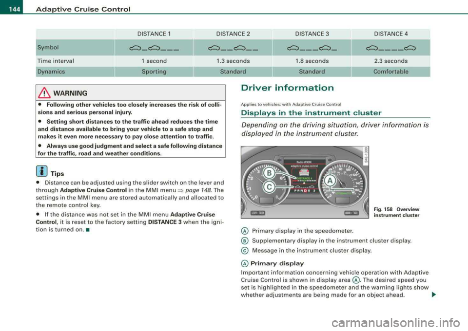
© Primary display in the speedometer .
Fig. 158 Overview
instrument cluster
@ Supplementary display in the instrument cluster display.
© Message in the instrument cluster display.
© Primary display
Important information concerning vehicle operation with Adaptive
Cruise Control is shown in display area @. Th e desired sp eed you
set is highlighted in the speedometer and the warning lights show
wh ether adjus tmen ts are being mad e for an objec t ahead .
.,,
Page 150 of 404
___ A_ d_a_ p_ ti_v _ e_ C_ ru_ is_ e_ C_ o_n_ t_ r_ o _ l ___________________________________________ _
The ACC sensor is dirty or blocked (e.g. leaves, snow).
The ACC sensor is located in the area under the front license plate.
If there is a loss of operation due to heavy contamination, this area
should cleaned to restore proper operation.
EPB activation
The text message EPB activation appears if emergency braking was
initiated with the Electromechanical Parking Brake (EPBl. Adaptive
Cruise Control is turned off. A gong sounds as a reminder.
ESP activation
The text message ESP activation appears if the Electronic Stabiliza
tion Program (ESP) has intervened to take control in a critical driving
situation. In this case Adaptive Cruise Control is automatically
turned off . A gong sounds as a reminder .
Speed range
The text message Speed range appears if the current speed is too
low to set or to hold the requested speed.
When setting a desired speed, it must be at least 20 mph (30 km/h).
At speeds below 17 mph (25 km/h), the cruise control is turned off.
Shift lever position!
The text message Shift lever position! appears when the shift select
lever is moved to position
N. In this position, Adaptive Cruise
Control is not available. •
Applies to veh ic les: with Ad apt ive Crui se Contro l
Settings in MMI
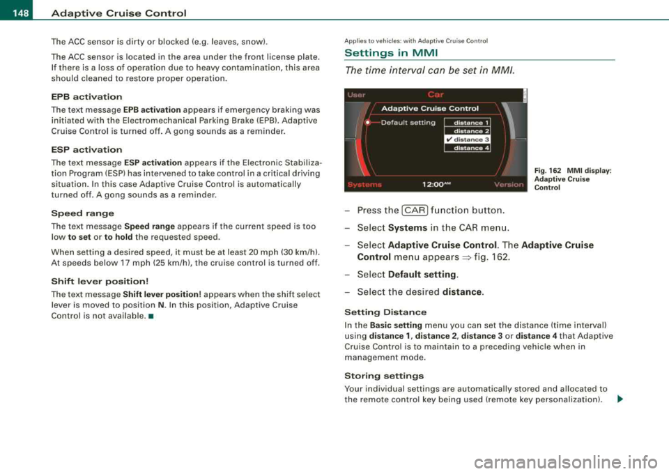
The time interval can be set in MM/.
-Press the [CAR] function button.
-Select Systems in the CAR menu.
Fig. 162 MMI display :
Adaptive Cruise Control
-Select Adaptive Cruise Control. The Adaptive Cruise
Control
menu appears~ f ig . 162.
-Select Default setting .
-Select the desired distance.
Setting Distance
In the Basic setting menu you can set the distance (time interval)
using
distance 1, distance 2, distance 3 or distance 4 that Adaptive
Cruise Control is to maintain to a preceding vehicle when in
management mode.
Storing settings
Your individual settings are automatically stored and allocated to
the remote control key being used (remote key personalization) .
~
Page 155 of 404
![AUDI S8 2008 Owners Manual Audi lane a ssist -
----------------
-Sele ct Warning early , adaptive or late => page 152,
fig. 170 .
Sett ing th e st eering wh eel vibration
-Pressthe(CAR]function button.
-Selec t Syst](/img/6/57619/w960_57619-154.png "AUDI S8 2008 Owners Manual Audi lane a ssist -
----------------
-Sele ct Warning early , adaptive or late => page 152,
fig. 170 .
Sett ing th e st eering wh eel vibration
-Pressthe(CAR]function button.
-Selec t Syst")
Audi lane a ssist -
----------------
-Sele ct Warning early , adaptive or late => page 152,
fig. 170 .
Sett ing th e st eering wh eel vibration
-Pressthe(CAR]function button.
-Selec t Systems in the CAR menu .
-Select Audi lane a ssis t.
-Selec t Steering vibration weak, medium or strong.
Setting th e warning tim e
E a rl y:
This setting warns the driver before a wheel touches the
detected lane boundary line. The warning depends on the ve hicle's
angle as it approaches the boundary line . If you approach a
boundary l ine gradua lly, the warning will occur ear lier. If you
approach the boundary line at a very sharp angle, the warning wi ll
occur just before a whee l touches the l ine.
A dapti ve : In this setting, the warning time adjusts to the character
istics of the road and the vehic le speed. The warning occurs later for
curves and occurs ear lier for straight stretches of road . The warning
occurs later on narrow roads than on wide roads.
Late: Th is setting warns the driver when a whee l drives over the
detected lane boundary line.
Setting th e steering wheel vibrati on
When adjusting the steering whee l vibration, the steering wheel
v ibrates so that you can check the intensity you have set.
[ i ] Tips
• When making the adjustment, lane assist is not activated . The
steering whee l vibrates briefly only to assist you in changing the
se tting .
• Your settings are automatically stored and assigned to the
remote contro l key being used. •
Controls and equip
ment
Page 162 of 404
___ A_ u_ d_ i_s _i_d _e_ a_ s_ s
_ is_ t __________________________________________________ _
-Select Audi sid e ass is t.
-Select W arning l amp : brightn ess.
-Rotate the control knob to adjust the displayed bright -
ness of the signal l ight on the outside mirrors
=> page 159, fig. 180 .
Th e brightn ess o f th e signal light for both th e informational and
a lert stages is automatica lly adj usted to ambient light conditions. In
addition, you can adjust the
basic brightness separately, via the
brightness function
=> page 159, f ig. 180.
While mak ing the adjustment , the new br ig htness setting is
displayed briefly. The brightn ess disp layed is that of the informa
tiona l stage s ignal. The alert stage signal brightness is linked to the
in formational stag e signal brightness .
The infor mationa l stage signal br ightness should be adjusted so
that you notice the signa l illumination when you look in the outside
m irror, but not when you look forward through the windsh ield.
In very dark or light surround ings , the automat ic brightness setting
adjusts signal light brightness to maximum or minimum intensity ,
as needed . In circumstances such as these, you may not not ice any
change in the brightness on the outside m irror wh en adjusting the
basic brightness .
You may not notice the change until ligh ting conditions are normal
aga in .
[ i ] Tip s
• Side assist is not active wh en the basic brightness is adjusted .
The signal l ight comes on briefly to help you make the adjustment.
• Your settings are automatically s tored and assigned to the
remote contro l key being used. •
App lies to ve hicles: w ith s ide assis t
General information
Side assist has lim its and cannot detect vehicles under all road and
weather conditions. Please remember system limit ations and never
rely on the system, especia lly when:
• driving through
curves=> page 160,
• l anes are of different widths => page 160. •
Applies to ve hicles : w ith sid e as sist
When driving through curves
Side assist cannot detect vehic les in curves with a turning radius of
l ess than
218 yards (200 m) .
When driving through a curve , it is poss ib le that side assist may
register a vehicl e two lanes over, and the signal on the outside
m irror w ill light up .•
A pplies to vehicle s: w ith sid e ass is t
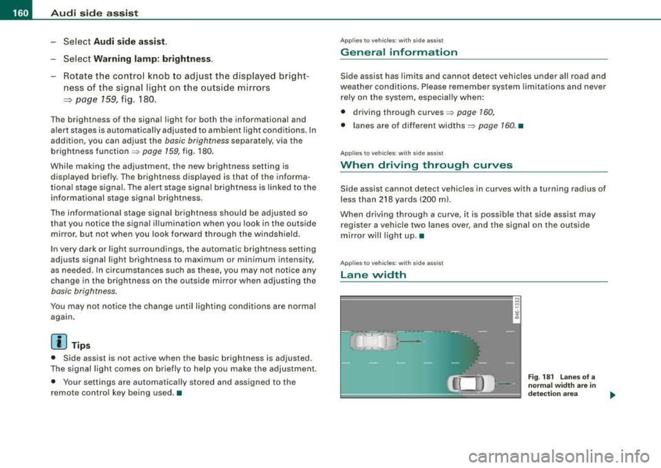
Lane width
w cl,
Fig . 18 1 L an es of a
norma l widt h are i n
d etec tion area
Page 183 of 404
___________________________________________ A_ d_ v_ a_n _ c_ e_ d_ P_a _ r_ k_ i_n --=g=-- S_ y=--- s_t _
e _m _ ___._
The volume and frequency settings are automatically stored and
assigned to the remote master key.
& WARNING
Always make sure that the volume and frequency of the chimes is
adjusted so that you can easily hear the acoustic distance signal
even if the radio is playing, the air -conditioner blower is on High or
there is a high level of outside noise . Check the settings whenever
someone else has driven the vehicle before you. •
Applies to vehic les: with Advanced Parking System with rear view camera
Adjusting the chimes -option 2
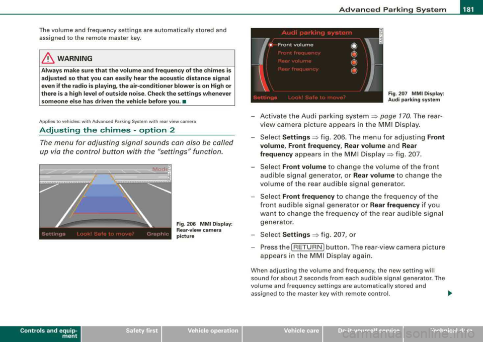
The menu for adjusting signal sounds can also be called
up via the control button with the "settings" function.
Controls a nd eq uip
ment
Fig . 206 MMI Display:
Rear-view camera
picture Fig
. 207 MMI Display:
Audi parking system
-Activate the Audi parking system~ page 770. The rear
view camera picture appears in the MMI Display.
-Select Settings ~ fig. 206. The menu for adjusting Front
volume , Front frequency , Rear volume
and Rear
frequency
appears in the MMI Display => fig. 207.
Select
Front volume to change the volume of the front
audible signal generator, or
Rear volume to change the
volume of the rear audible signal generator.
-Select Front frequency to change the frequency of the
front audible signal generator or
Rear frequency if you
want to change the frequency of the rear audible signal
generator.
-Select Settings ~ fig. 207, or
-Press the [ RETURN I button. The rear-view camera picture
appears in the MMI Display again.
When adjusting the volume and frequency, the new setting will
sound for about 2 seconds from each audible signal generator. The
volume and frequency settings are automatically stored and
assigned to the master key with remote control.
~
Vehicle care I I irechnical data
Page 193 of 404

___________________________________________________ H_ o_m_ e_ L_ i_ n _ k_ ®_ R __ l!III
Homelink ®
Universal remote control
Applies to vehicles: w ith Home link® unive rsa l remo te cont rol
General information
The HomeLink® feature can learn up to three radio
frequency codes for most current transmitters used for
operating garage doors, estate gates, home or outdoor
lighting systems, and other devices.
You must first program the Homelink® transmitter before you can
use the
system=> page 191, "Programming the Homelink® trans
mitter".
In order to program the Homelink® transmitter for devices utilizing
rolling code , a second person on a ladder who can safely reach the
garage door opener motor is recommended. It is also necessary to
locate the
"learn" button on your garage door opener motor . Refer
to the operating instructions for the opener, as the location and
color of this button may
vary by manufacturer.
You can still use the original remote control for the device at any
time.
& WARNING
• Never use the Homelink"" transmitter with any garage door
opener that does have not the safety stop and reverse feature as
required by federal safety standards. This includes any garage
door opener model manufactured before April 1, 1982.
• A garage door opener which cannot detect an object, signaling
the door to stop and reverse does not meet current federal safety standards . Using a garage door opener without these features
increases risk of serious injury or death.
Controls and equip ment
& WARNING (continued)
• For safety reasons never release the parking brake or start the
engine while anyone is standing in front of the vehicle.
• A garage door or an estate gate may sometimes be set in
motion when the Homelink® remote control is being
programmed. If the device is repeatedly activated, this can over
strain motor and damage its electrical components -an over
heated motor is a fire hazard!
• To avoid possible injuries or property damage, please always
make absolutely certain that no persons or objects are located in
the range of motion of any equipment being operated. •
Applies to vehicles : wit h Home link ® uni vers al remote con trol
Programming the Homelink ® transmitter
The transmitter is programmed in two phases. For rolling
code transmitters, a third phase is also necessary.
f ( ~ ~
i
s: 0
,1, .., Cl)
ll
Fig . 213 Overhead
console: Homelink®
keypad
~
Page 194 of 404
--~H~o~m~e:_!L~i~n~k~®~ ----------------------------------------------
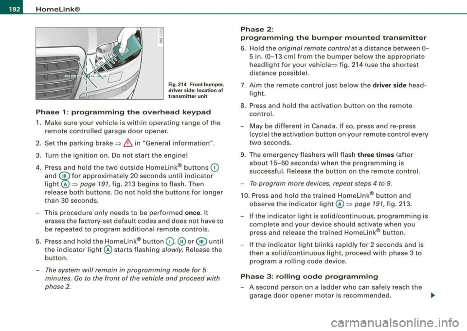
Fig. 214 Front bumper,
driver side: location of
transmitter unit
Phase 1: programming the overhead keypad
1. Make sure your vehicle is w ithin operat ing range of the
remote controlled garage door opener .
2. Set the parking
brake ::::,&, in "General information".
3. Turn the ignition on. Do not start the engine!
4. Press and hold the two outside Homelink ® buttons
(D
and @ for approxim~tely 20 sec _onds until indicator
light @::::,
page 191, fig. 213 begins to flash. Then
release both buttons. Do not hold the buttons for longer
than
30 seconds.
- This procedure only needs to be performed
once. It
erases the factory-set default codes and does not have to
be repeated to program add itional remote controls.
5. Press and hold the Homelink ® button
(D , ® or @ until
the indicator light @starts flashing
slowly. Release the
button.
- The system will remain in programming mode for 5
minutes.
Go to the front of the vehicle and proceed with
phase 2.
Phase 2:
programming the bumper mounted transmitter
6. Hold the original remote control at a d istance between 0 -
5 in. (0-13 cm) from the bumper below the appropriate
headlight for your
vehicle ::::, fig. 214 (use the shortest
distance possible).
7 . A im the remote control just below the
driver side head
l ight.
8. Press and hold the activation button on the remote control.
- May be different in Canada. If so , press and re-press
(cycle) the activation button on your remote control every
two seconds .
9. The emergency flashers will flash
three times (after
about
15-60 seconds) when the programming is
successful. Release the button on the remote control.
- To program more devices, repeat steps 4 to 9.
10. Press and hold the trained Homelink® button and
observe the indicator
light @=:> page 191, fig. 213.
If t he indicator light is solid/continuous, programming is
complete and your device should activate when you
press and release the tra ined Homelink® button.
-If the indicator light blinks rapidly for 2 seconds and is
then a solid/continuous light, proceed with phase 3 to
program a roll ing code device.
Phase 3: rolling code programming
-A second person on a ladder who can safely reach the
garage door opener motor is recommended.
..,
Page 195 of 404
___________________________________________________ H_ o_m_ e_ L_ i_ n _ k_ ®_ R __ ffllll
11 . Locate the "lea rn" button on the garage door opener
motor (refer to the operating instructio ns fo r the opener,
as the location of this button may vary by man ufacturer).
12 . Press and release the learn button on the garage door
opener motor .
-Not e: once the button is pressed, there are 30 sec ond s in
which to init iate the next step .
13. On the Homelink® keypad inside the vehicle, firmly press and hold the Home link® button previously
programmed in phases 1 and 2 for two seconds and
release . Repeat this sequence
twi ce.
- Some vehicles may require the press/ho ld/re lease
sequence up to three times to complete the training
process.
Homelink® should now activate your rolling code
equipped device.
If the 5 minute time limit is exceeded, the emer gen cy flas her s will
flas h one t im e to indicate that the process has been terminated. In
this case, repeat steps 4 through 9.
If the emergency flashers do not flash
three t imes (after about 15 -
60 seconds), programming was not successful. In this case, repeat
steps 4 through 9.
Remote control units for garage door openers in Canada are set to
stop transmitting radio frequency signa ls after two seconds. This
time may not be suffic ient for the Homelink® system to learn the
radio frequency signal. Perform a ll other steps as described
above. •
Controls and equip
ment
Applies to vehicles: with Homel ink® universa l remote contro l
Operating the Homelink ® transmitter
The Homelink® transmitter works in the same manner as
the original handheld remote contr ol that came with the
system.
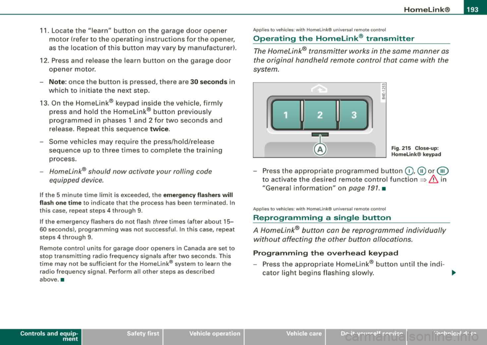
Fig. 2 15 C lose- up:
H omelink® keypa d
- Press the appropriate programmed button (D, ® or @
to act ivate the des ired remote control function => & in
"General information" on
page 191. •
Applies to vehicles: with Homel ink® universa l remote control
Reprogramming a single button
A Homelink® button can be reprogrammed individually
without affecting the other button allocations.
P rogr amming th e ov erhead keypad
- Press the appropriate Homelink® button unt il the indi-
cator lig ht begins flash ing s lowly .
~
Page 196 of 404
___ H_ o_m_ e_ L_ i_ n _k_ ® __________________________________________________ _
Pr og ram min g th e bump er m ount ed tr ansmitt er
1. Hold t he original remote control at a distance between 0-
5 in . (0-13 cm) from the bumper below t he appropriate
headlight for your vehic le (use the shortest distance
poss ible) .
2. Aim the remote control just below the driver side head
l ight.
3. Press and hold the activation button on the remote control.
4. The emergency f lashers will flash three times (after
about
15-60 seconds) when the programming is
successful. Now release the button on the remote
control.
- I f the dev ice utilizes a ro llin g code, please follow phase 3
of~ page 191, "Programming the Home link® trans
mitter" for ro lling code programming .
This pro cedur e wi ll cau se t he ex istin g pro gra mm ing on th e
H om elin k® butt on to be erase d!•
A pplies to vehi cles : wit h Ho meli nk® u niv er sal re m ote con tro l
Erasing the programming of the Homelink ®
transmitter
When you erase the programming, the programming on
all three of the transmitter channels with be lost!
- Pe rform steps 1 to 4 as described on ~ page 192 , "Phase
1 : programming the overhead keypad".
When comp leted, the Homelink ® system will be in the program
m ing mode a nd is t hen ready to learn the codes for remote
controlled devices.
[ i ] T ip s
• Programmed buttons cannot be erased ind ividua lly.
• For security reasons you are advised to erase the programming
of the Homelink ® system before you sel l your vehic le. •
Applies to vehicle s: with Ho melink® universa l re m ote c ont ro l
Information and accessories
If you wou ld like more information on Homelink ®, where to
purchase the Homelink® compatib le products, or would like to
purchase the Homelink ® Home Lighting Package, please cal l toll
free: 1 -800-355 -3515.
[ i ] T ip s
• The Homelink ® universal transmitter compl ies with part 15 of
the FCC ru les and RSS -210 of IC part 15. Operation is subject to the
f ollowing cond it ions :
- this device may not cause harmful interference, and
- this device must accept any interference that may be received
including interference that may cause undesired operation .
• Changes or mod ificat ions not express ly approved by the party
responsible for compliance cou ld void the user's authority to
operate the device (DOC : ISTC 1763 102 264 Pr ince MODE L/FCC ID :
CB2 V94800l.
•
Page 277 of 404
Intellig ent tec hnol ogy -
------------ -=--=-= '-
vidual components . It regulates consumption, so that more elec
t rical energy is not be ing used than is be ing genera ted and ensures
an optimal state of charge for the battery .
[ i ] Tip s
• But even energy management cannot negate the limits of
physics. Consider that the power and life of a battery are limited.
• If starting ability is threatened, you are informed by a warning
~ page 275, "Driver notification in the instrument cluster
display" .•
What you should know
The highest priority is given to maintaining starting capa
bility.
T he battery is severely taxed in short -distance driving, in city traffic
and during t he co ld time of year . Abundant e lectrica l energy is
required, but on ly a little is generated . It is also critical if the engine
is not running and e lectrical components are turned on. In this
instance energy is being consumed but none is being generated .
I t is in precisely these situations that you wi ll notice energy manage
ment active ly regulating the d istr ibut ion of energy.
Vehicl e stands for an extended period
If you do not drive your vehicle over a per iod of several days or
weeks, electrica l components are gradually cut back or switched off.
This reduces energy consu mpt ion and maintains starting capability
over a longer period .
Be aware t hat when you unlock you r ve hicle, some o f the conve
nience functions may not operate, such as the Advanced Key, the
remote contro l or t he power seat adjustment. T he convenience
functions will be available again when you turn on the ignition and start the engine .
Controls and equip
ment Safety first Vehicle operation With th
e engin e turned off
If you listen to the radio, for examp le, with t he engine tu rned off or
use other MMI functions, the battery is being discharged.
I f starting capabi lity is jeopardized due to energy consumption, the
f o llow ing warn ing appears in t he MMI display:
Ple ase start engine , other wise sy stem will s witch off in 3
minute s.
The warning indicates that the system wi ll be turned off au tomat i
ca lly after 3 minutes. If you wish to continue using the functions,
you have to start the engine .
With the engine running
Although e lectrica l energy is generated when the vehic le is being
driven, the battery can become discharged. This happens mostly
when little energy is being generated and a great deal co nsumed
and the battery's state of charge is not optimal.
To br ing the ene rgy balance bac k into equi librium , cons umers
which require especially large amounts of energy are temporar ily
cu t back or switched off . Heating systems in part icu lar require a
great deal of energy. If you notice, for example, that the heated
seats* o r the heated rear w indow are not heating, they have been
temporari ly cut back or switc hed off. These systems wil l be avai lable
again as soon as the energy balance has been restored.
You wil l also notice t hat engi ne idle speed has been increase d
s lightly . This is norma l and not a cause for concern . By increasing
engine idle speed the addi tiona l energy required is ge nerated a nd
the battery is charged. •
Driver notification in the instrument cluster
display
I f the battery's state of charge is not in the optima l range, this driver
no tificat io n ap pears in the instrument cl uster d isplay:
t:3 Low battery ch arge : battery will be charged while dri ving .,_
Vehicle care Do-it-yourself service Technical data