AUDI TT 1998 8N / 1.G ATW Engine Motronic Fuel Injection Syst
Manufacturer: AUDI, Model Year: 1998, Model line: TT, Model: AUDI TT 1998 8N / 1.GPages: 81, PDF Size: 1.03 MB
Page 11 of 81
24-10
Repair Manual, 1.8 Liter 4
-Cyl. 5V Turbo Engine
Mechanical, Engine Code(s): AEB, ATW, Repair Group 21, Charge air system with turbocharger, checking
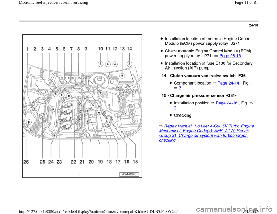
Installation location of motronic Engine Control
Module (ECM) power supply relay -J271-
Check motronic Engine Control Module (ECM)
power supply relay -J271- Page 28
-13
Installation location of fuse S130 for Secondary
Air Injection (AIR) pump
14 -
Clutch vacuum vent valve switch -F36-
Component location Page 24
-14
, Fig.
3
15 -
Charge air pressure sensor -G31-
Installation position Page 24
-16
, Fig.
7
Checking:
Pa
ge 11 of 81 Motronic fuel in
jection s
ystem, servicin
g
11/21/2002 htt
p://127.0.0.1:8080/audi/servlet/Dis
play?action=Goto&t
yp
e=re
pair&id=AUDI.B5.FU06.24.1
Page 12 of 81

24-11
16 -
Throttle valve control module -J338-
With throttle drive (power accelerator
actuation) -G186-, angle sensor -1- for
throttle drive (power accelerator actuation)
-G187-, and angle sensor -2- for throttle
drive (power accelerator actuation) -G188- Checking Page 24
-120
17 -
Intake Air Temperature (IAT) sensor -G42-
Checking Page 28
-21
18 -
Recirculating valve for turbocharger-
N249-
Installation position Page 24
-14
, Fig.
4
Blue harness connector
19 -
Knock Sensor (KS) 1 -G61-
20 -
Knock Sensor (KS) 2 -G66-
21 -
Camshaft Position (CMP) sensor 2 -G40- Checking Page 28
-45
Pa
ge 12 of 81 Motronic fuel in
jection s
ystem, servicin
g
11/21/2002 htt
p://127.0.0.1:8080/audi/servlet/Dis
play?action=Goto&t
yp
e=re
pair&id=AUDI.B5.FU06.24.1
Page 13 of 81
24-12
Repair Manual, 1.8 Liter 4
-Cyl. 5V Turbo Engine
Mechanical, Engine Code(s): AEB, ATW, Repair Group 21, Charge air system with turbocharger, checking
Repair Manual, 1.8 Liter 4
-Cyl. 5V Turbo Engine
Mechanical, Engine Code(s): AEB, ATW, Repair Group 26; Secondary Air Injection (AIR) system, checking
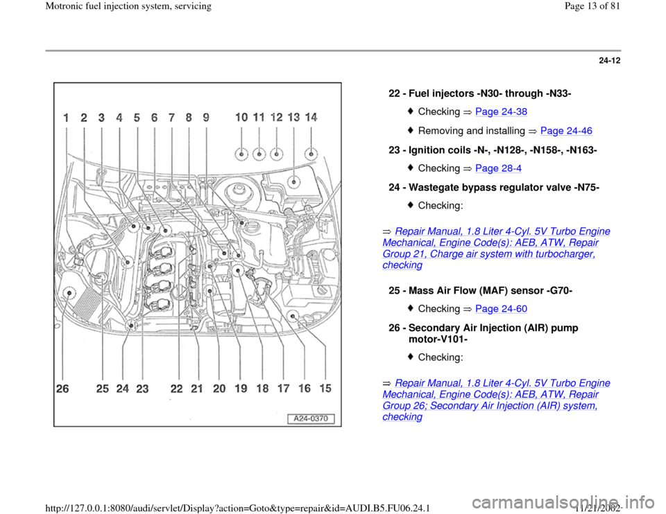
22 -
Fuel injectors -N30- through -N33- Checking Page 24
-38
Removing and installing Page 24
-46
23 -
Ignition coils -N-, -N128-, -N158-, -N163-
Checking Page 28
-4
24 -
Wastegate bypass regulator valve -N75-
Checking:
25 -
Mass Air Flow (MAF) sensor -G70-
Checking Page 24
-60
26 -
Secondary Air Injection (AIR) pump
motor-V101-
Checking:
Pa
ge 13 of 81 Motronic fuel in
jection s
ystem, servicin
g
11/21/2002 htt
p://127.0.0.1:8080/audi/servlet/Dis
play?action=Goto&t
yp
e=re
pair&id=AUDI.B5.FU06.24.1
Page 14 of 81
24-13
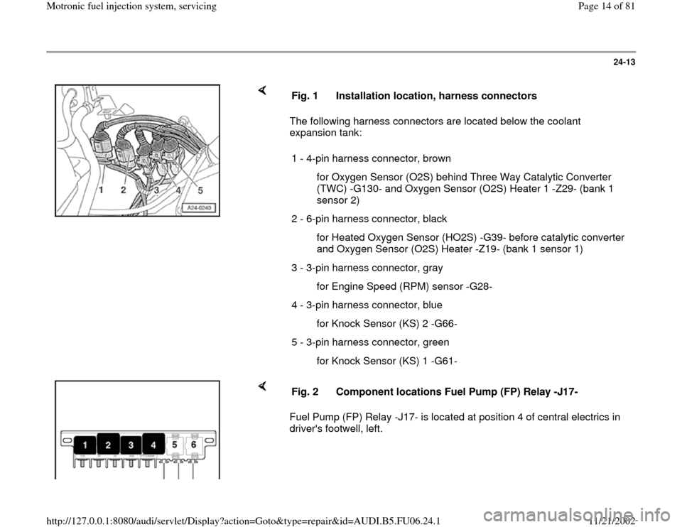
The following harness connectors are located below the coolant
expansion tank: Fig. 1 Installation location, harness connectors
1 - 4-pin harness connector, brown
for Oxygen Sensor (O2S) behind Three Way Catalytic Converter
(TWC) -G130- and Oxygen Sensor (O2S) Heater 1 -Z29- (bank 1
sensor 2)
2 - 6-pin harness connector, black
for Heated Oxygen Sensor (HO2S) -G39- before catalytic converter
and Oxygen Sensor (O2S) Heater -Z19- (bank 1 sensor 1)
3 - 3-pin harness connector, gray
for Engine Speed (RPM) sensor -G28-
4 - 3-pin harness connector, blue
for Knock Sensor (KS) 2 -G66-
5 - 3-pin harness connector, green
for Knock Sensor (KS) 1 -G61-
Fuel Pump (FP) Relay -J17- is located at position 4 of central electrics in
driver's footwell, left. Fig. 2 Component locations Fuel Pump (FP) Relay -J17-
Pa
ge 14 of 81 Motronic fuel in
jection s
ystem, servicin
g
11/21/2002 htt
p://127.0.0.1:8080/audi/servlet/Dis
play?action=Goto&t
yp
e=re
pair&id=AUDI.B5.FU06.24.1
Page 15 of 81
24-14
Note:
In order to assure sufficiently secure fitting, switches must not be installed
more than once.
Adjusting switch:
Repair Manual, Brake System, Repair Group 46, Brake booster, removing and installing
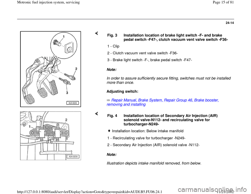
Fig. 3 Installation location of brake light switch -F- and brake
pedal switch -F47-, clutch vacuum vent valve switch -F36-
1 - Clip
2 - Clutch vacuum vent valve switch -F36-
3 - Brake light switch -F-, brake pedal switch -F47-
Note:
Illustration depicts intake manifold removed, from below. Fig. 4 Installation location of Secondary Air Injection (AIR)
solenoid valve-N112- and recirculating valve for
turbocharger-N249-
Installation location: Below intake manifold
1 - Recirculating valve for turbocharger -N249-
2 - Secondary Air Injection (AIR) solenoid valve -N112-
Pa
ge 15 of 81 Motronic fuel in
jection s
ystem, servicin
g
11/21/2002 htt
p://127.0.0.1:8080/audi/servlet/Dis
play?action=Goto&t
yp
e=re
pair&id=AUDI.B5.FU06.24.1
Page 16 of 81
24-15
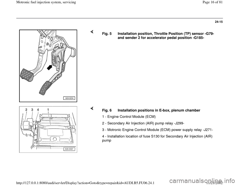
Fig. 5 Installation position, Throttle Position (TP) sensor -G79-
and sender 2 for accelerator pedal position -G185-
Fig. 6 Installation positions in E-box, plenum chamber
1 - Engine Control Module (ECM)
2 - Secondary Air Injection (AIR) pump relay -J299-
3 - Motronic Engine Control Module (ECM) power supply relay -J271-
4 - Installation location of fuse S130 for Secondary Air Injection (AIR)
pump
Pa
ge 16 of 81 Motronic fuel in
jection s
ystem, servicin
g
11/21/2002 htt
p://127.0.0.1:8080/audi/servlet/Dis
play?action=Goto&t
yp
e=re
pair&id=AUDI.B5.FU06.24.1
Page 17 of 81
24-16
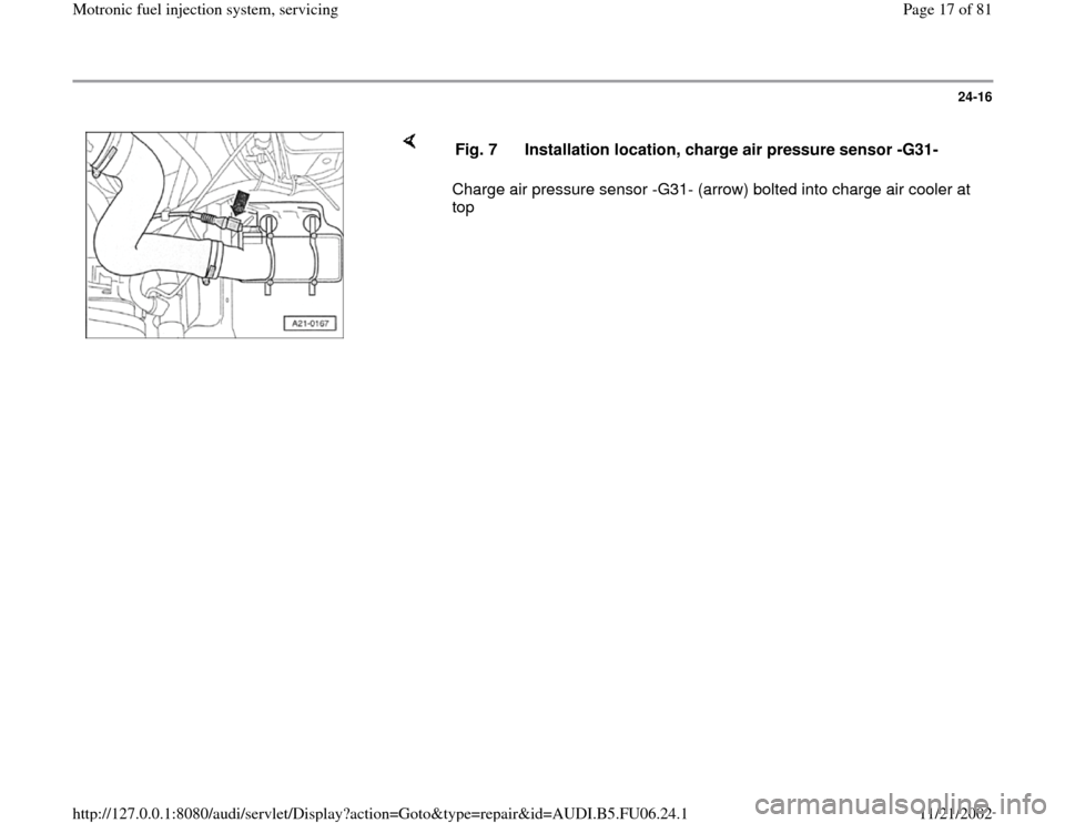
Charge air pressure sensor -G31- (arrow) bolted into charge air cooler at
top Fig. 7 Installation location, charge air pressure sensor -G31-
Pa
ge 17 of 81 Motronic fuel in
jection s
ystem, servicin
g
11/21/2002 htt
p://127.0.0.1:8080/audi/servlet/Dis
play?action=Goto&t
yp
e=re
pair&id=AUDI.B5.FU06.24.1
Page 18 of 81

24-17
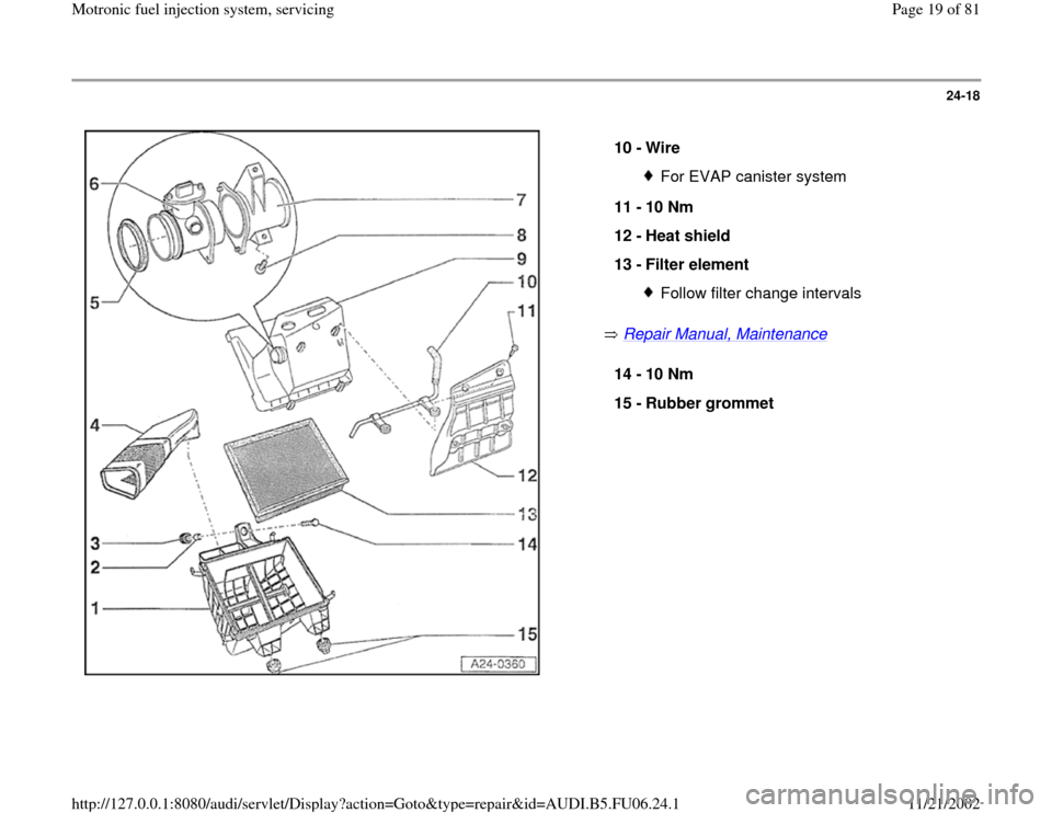
Air cleaner, disassembling and
assembling
1 -
Lower part of air cleaner housing
2 -
Sleeve
3 -
Rubber grommet
4 -
Air duct
to metering unit
5 -
Seal
6 -
Mass Air Flow (MAF) sensor -G70- Checking Page 24
-60
7 -
Air duct
8 -
6 Nm
9 -
Upper part of air cleaner housing
Pa
ge 18 of 81 Motronic fuel in
jection s
ystem, servicin
g
11/21/2002 htt
p://127.0.0.1:8080/audi/servlet/Dis
play?action=Goto&t
yp
e=re
pair&id=AUDI.B5.FU06.24.1
Page 19 of 81
24-18
Repair Manual, Maintenance
10 -
Wire
For EVAP canister system
11 -
10 Nm
12 -
Heat shield
13 -
Filter element Follow filter change intervals
14 -
10 Nm
15 -
Rubber grommet
Pa
ge 19 of 81 Motronic fuel in
jection s
ystem, servicin
g
11/21/2002 htt
p://127.0.0.1:8080/audi/servlet/Dis
play?action=Goto&t
yp
e=re
pair&id=AUDI.B5.FU06.24.1
Page 20 of 81
24-19
Wiring and component testing using
VAG1598/31 test box
Note:
VAG1598/31 test box is designed so that it can
be simultaneously connected to the wiring
harness at the Engine Control Module (ECM)
and also to the ECM itself.
This is advantageous because electronic
engine control remains fully functional (e.g.
measurement of signals with engine running)
when the test box is attached.
Relevant test procedures note whether Engine
Control Module (ECM) should also be
connected to the test box or not.
Always use VAG1594A connector test kit to
attach measurement devices (e.g. VAG1527B
voltage tester, VAG1526 multimeter etc.).
WARNING!
To avoid damaging electronic components,
set measuring range before connecting test
leads and observe all test requirements.
Pa
ge 20 of 81 Motronic fuel in
jection s
ystem, servicin
g
11/21/2002 htt
p://127.0.0.1:8080/audi/servlet/Dis
play?action=Goto&t
yp
e=re
pair&id=AUDI.B5.FU06.24.1