lock AUDI TT COUPE 2009 Owners Manual
[x] Cancel search | Manufacturer: AUDI, Model Year: 2009, Model line: TT COUPE, Model: AUDI TT COUPE 2009Pages: 316, PDF Size: 71.16 MB
Page 4 of 316
Table of contents
Table of contents
Vehicle literature ........ .
About this Owner's Manual .............. ...... . .
Controls and
equipment .. .. ... . .. ... ... . .
Cockpi t ... .......... ...... ..... .
Genera l ill ustration ............. .
Instruments and
warning/indica tor lig hts ....... .
Instruments .............. ..... .
Warning/indicator lights ........ .
Driver informa tion system ..... .
Introduction ............... .. .. .
Gearshift recommendation ...... .
Service interval d isplay .... ..... .
On -Boa rd Diag nos tic sys tem (OBD)
Trip computer ..... ... .. ..... .. .
Menu display ............•......
Speed war ning system ....... .. .
Warnings and symbo ls .... ... .. .
O pening and closing .......... .
Keys .......................... .
Powe r loc king system ......... . . 5 Rear
lid/trunk lid .............. .
45
Transmission . . . . . . . . . . . . . . . . . . . 9 9
Anti-theft a larm system ..... ... .
47 Manua l transmiss ion . . . . . . . . . . . . 99
Power w indows ...... ... .... . .
48 S tronic transmission . . . . . . . . . . . 99
Clear vision ................ ... .
6 Lights ........................ . 51
Home
link® . . . . . . . . . . . . . . . . . . . . . 107
51 Universa I remote control . . . . . . . . 107
9
11
11
1 2
12
1 5
22
2 2
23
23
24
25
27
30
32
38
38
41 In
ter io r ligh ts . . . . . . . . . . . . . . . . . . 59
Vis ion . . . . . . . . . . . . . . . . . . . . . . . . . 59
W iper and washer system . . . . . . . 60
M irrors . . . . . . . . . . . . . . . . . . . . . . . . 64
Digi tal compass . . . . . . . . . . . . . . . . 67
Seats and sto rage . . . . . . . . . . . . . 69
Genera l recommendat ions . . . . . . 69
Adjust ing front sea ts manua lly . . 70
Power seats ........ ......... . .
Lumbar support ............... .
Head restraints ........ ..... .. .
Rear sea ts . ... ... . .. ... ... .. .. .
Luggage compar tment ........ .
Roof rack ..... .......... ....• ..
Cup ho lder ... ... ...... ... .. .. .
Asht ray ................ .... .. .
Cigarette ligh ter /socke t ........ .
Storage ............ ....... ... .
Warm and cold .............. . .
Climate cont ro ls ........... ... .
Rear window defogger
Qiil ...•. ..
Heated seats ................. .
On t he road ... .• ..... .... ... ...
Steering ... ... ... ...... ... ... . .
Ignition lock and ignition switch .
Sta rting and stopping the engine
Par king bra ke ... ... ... .. .. .... .
Acoustic parking system ... .. .. .
Cruise control ................. .
Audi magnetic ride ......... ... . 71
Safety first
................ .
74
74 Driving Safe ly .... ............. .
75 General no tes ................. .
76 Proper occupant seating pos itions
79 D river and passenger side fo otwel l
81 Peda l area .................... .
81 Stow ing luggage .............. .
8 2 Report ing Safety Defects ...... . .
83 Sa fety belts ..... ... ... ....... . .
8 5 General no tes ................. .
85 Why safety be lts? .............. .
89 Safety bel ts ..... ... ... ... ... .. .
90 Safety belt pretensioners ....... .
91
Ai rbag system . ...... .......... .
91 Importa nt t hings to know ...... .
92 Fro nt airbags ................. .
93 Monitoring the Advanced Airbag
94 System ....................... .
95 Knee airbags ..... ............. .
96 Side airbags ... ... ............ .
98 1
13
1 14
1 14
116
120
1 2 0
121
123
125
125
126
129
133
135
13 5
139
146
151
154
Page 13 of 316
Cockpit
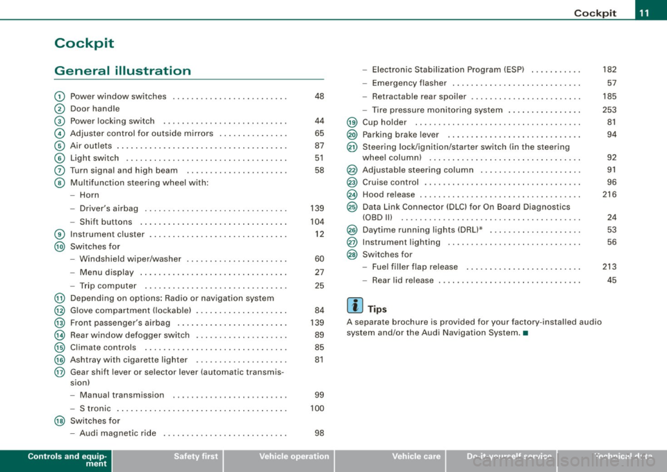
General illustration
G)
0
©
©
©
©
0
©
®
@
Power window switches
Door handle
Pow er lo cking switc h
Adjus te r contro l fo r ou tsid e mirro rs ...... .... ... . .
Air outlets ..... .. . ..... .... .... .. . .... .. . ..... .
Light switch .. ...... .... ... .... .... .... .... ... .
Turn signa l and high beam
Multifunc tion steering wheel with:
- Horn
- Driver's a irbag .... .... ... .... .... .... .... ... .
- Shift b uttons ... .. .... ... .... .... .... .... ... .
Instr um en t cluster . ...... ... .... .. ...... .. .. ... .
Switches for
- Windshield wipe r/wash er ... .... .. ....... .. ... .
- Menu d isplay ...... ... .. .. .... .... .... ... ... .
- Trip computer ..... .. .... .... ...... ....... .. .
@ Depending on options : Radio or navigation sys tem
@ G love compa rtmen t (loc kab le) ... .. .. .. ... .... ... .
@ Front passenger 's airbag .. ...... .. . .... .. .. .... .
@ Rear window defogger switch .... ..... .. .... .... .
@ Climate controls ..... .. .... .... ..... .. ... ... .. .
@ Ashtray wi th cigare tte lighter ....... ............ .
@ Gear shift l ever or s elector lever (automatic transmis -
sion)
48
4 4
65
87
5 1
58
139
104
1 2
60
27
25
84
139
89
85
81
- Manual transm ission . . . . . . . . . . . . . . . . . . . . . . . . . 99
- S tronic . . . . . . . . . . . . . . . . . . . . . . . . . . . . . . . . . . . . . 100
@ Switches for
- Aud i magnetic r ide
Controls and equip
ment
98
Co ckpit
- Electronic Stabilization Program (ESP) . .... .. ... .
- Emerge ncy flasher ... .. .. .. .... .... .... .. . ... .
- Retractab le r ear spoiler .... ...... .... .... .... . .
- Tire pressure mon itor ing system ..... .... .. . ... .
@ Cup holde r ....... .. .... .... .... ... ... ... .. ... .
@) Parking brake lever ... ...... .... ... .. .... .... .. .
@ Ste ering lock/ igni tion/starter switch (in the ste ering
whee l colum n) . .... .. .... ... .... .... .... .... .. .
@ Adjustab le steering co lumn .. .... ...... ... .. .... .
@ Cruise contro l .. .... .... ... .... .... ..... ... .... .
@ Hood release . .... ....... ... ... .. .... .... ...... .
@ Data Link Connector (DLC) for On Board Diagnos tics
(OBD Ill ..... .... ...... ... .. .... .... .... ... ... .
@ Daytime running ligh ts (DRU* ...... .. .... .... ... .
@ Instrumen t lighting .. ... ....... .... ....... ..... .
@ Switches for
- Fue l filler flap releas e .... .. .... .... .... ... ... .
- Rear lid release
[ i ] Tips
A separate b rochure is provided for your factory -ins ta lled audio
system and /or the Audi Navigation System .•
I • •
182
57
185
253 81
94
9 2
91
96
216
24
53
56
213
45
Page 14 of 316
Inst rum ent s a nd warning /indi cato r li ghts
Instruments and warning/indicator lights
Instruments
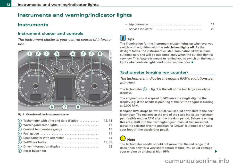
Instrument cluster and controls
The instrument cluster is your central source of informa
tion .
6
Fig . 2 Ove rv iew of the ins trum ent cluster
0
0
0
©
©
©
G)
©
Tachometer with time and date display ......•.....
Warning/indicator lights .. ... ..... ... ........ .. .
Coolant temperature gaug e .... ... ...... ...... .. .
Fuel gauge .. .... ... .. ...... .... ... ..... ... ... .
Speedome ter with odometer ..... .... ... .. .. ... .
Set/Chec k button ..... ... ..... ..... ... ........ .
Driver information display
Reset but ton for
~
"' N 9
i
12 , 13
15
13
14
14
13, 33
22
- trip odometer
- Service indicator
[ i ] Tip s
14
23
The illumination for the instrument cluster lights up whenever you
switch on the ign ition with the
ve hicle hea dlight s off. As the
daylight fades, the instrument cluster illumination likewise dims
automatically and wil l go out completely when the outside light is
very low. This feature is meant to remind you to switch on th e head
lights when outside light conditions become poor. •
Tachometer (engine rev counter)
The tachometer indicates the engine RPM (revolutions per
minutes) .
The tachometer 0 ~ fig. 2 is the left of the two large c lock -type
displays.
The engine turns at a speed
1,000 times the single digit in the
display, e.g . if th e ne edle is pointing a t the
"2" the engine is turning
at 2,000 RPM .
If engine RPM drops below 1,500, you should downshif t to the next
lower gear . The red ar ea at the end of th e scale indica tes maximum
permissible engine RPM after the break- in period. Before reaching
th is area , shift into the next higher gear (manua l transmission),
move the selec tor lever to position "D (Drive)" (automatic) or ease
your foot off the accelerator pedal.
0 Note
T he tachometer need le should not move into the red range . If it
does, then on ly for a very short period of time . You could damage
your engine by driving a t high RPM. ...
Page 15 of 316
<£> For the sake of the environment
Upshifting early saves fuel and reduces engine noise. •
Digital clock with date display
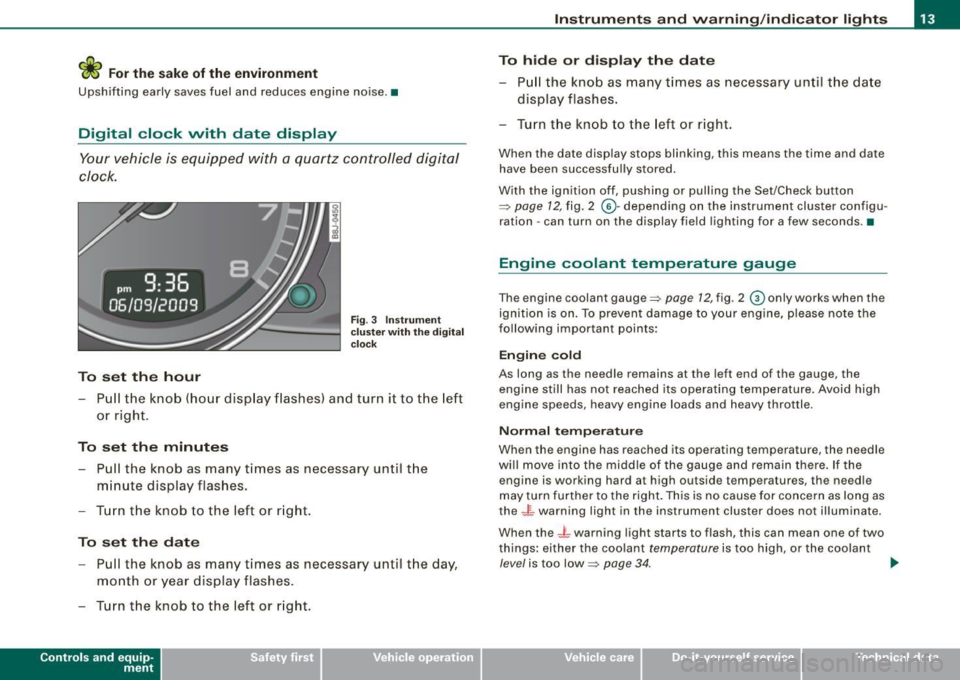
Your vehicle is equipped with a quartz controlled digital
clock.
To set the hour
Fig. 3 Instrument
c luste r with the digital
c lock
- Pull the knob (hour display flashes) and turn it to the left
or right.
To set the minutes
- Pull the knob as many times as necessa ry until the
m in ute display flashes.
- Turn the knob to the left or right.
To set the date
-Pull the knob as many times as necessary until the day,
month or year display flashes.
- Turn the knob to the left or right.
Con tro ls and eq uip
ment
Instruments and warning /indicator lights
To hide or display the date
- Pull the knob as many times as necessary until the date
display flashes .
- Turn the knob to the left or right.
When the date display stops blinking, this means the time and date
have been successfully stored.
With the ignition off, pushing or pulling the Set/Check button
~ page 12, fig. 2 ©-depending on the instrument cluster configu
ration - can turn on the display field lighting for a few seconds .•
Engine coolant temperature gauge
The engine coolant gauge~ page 12, fig. 2 © only works when the
ignition is on. To preven t damage to your engine, please note the
following important points:
Engine cold
As long as the needle remains at the left end of the gauge, the
engine still has not reached its operating temperature . Avoid high
engine speeds, heavy engine loads and heavy throttle.
Normal temperature
When the engine has reached its operating temperature, the needle
will move into the middle of the gauge and remain there. If the
engine is working hard at high outside temperatures, the needle
may turn further to the right. This is no cause for concern as long as
the -~- warning light in the instrument cluster does not illuminate.
When the
_J _ warning light starts to flash, this can mean one of two
things: either the coolant
temperature is too high , or the coolant
level is too low~ page 34. ~
Vehicle care I I irechnical data
Page 17 of 316
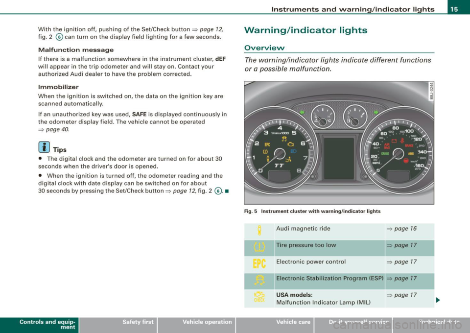
With the ignition off, pushing of the Set/Check button=> page 12,
fig. 2 © can turn on the display field lighting for a few seconds .
Malfunction message
If there is a malfunction somewhere in the instrument cluster,
dEF
will appear in the trip odometer and will stay on. Contact your
authorized Audi dealer to have the problem corrected.
Immobilizer
When the ignition is switched on, the data on the ignition key are
scanned automatically.
If an unauthorized key was used,
SAFE is displayed continuously in
the odometer display field . The vehicle cannot be operated
=> page 40.
[ i ] Tips
• The digital c lock and the odometer are turned on for about 30
seconds when the driver's door is opened .
• When the ignition is turned off, the odometer reading and the
digital clock with date display can be switched on for about
30 seconds by pressing the Set/Check button =>
page 12, fig. 2 @ . •
Con tro ls and eq uip
ment
Instruments and warning /indicator lights
Warning /indicator lights
Overview
The warning/indicator lights indicate different functions
or a possible malfunction.
Fig. 5 Instrument cluster with warning/indicator lights
Audi magnetic ride => page 16
Tire pressure too low => page 17
Electronic power control => page 17
-Electronic Stabilization Program (ESP) => page 17
USA models : => page 17
Malfunction Indicator Lamp (MIU
Vehicle care I I irechnical data
Page 18 of 316
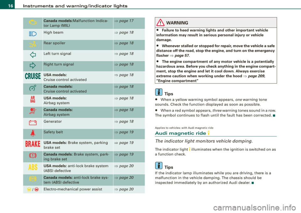
Instruments and warning/indicator lights
Canada models :M alfunct ion lndica -=> page 17
tor Lamp (MIU
D H ig h beam => page 18
Re ar s po iler => page 18
¢ L ef t tu rn s ignal => page 18
Q
Right turn signal => page 18
CRUISE
USA models: => page 18
Cruise con tro l ac tiva ted
0
Canada models: => page 18
Cr uise con trol activate d
AIR USA models : => page 18
BAG Airbag system
.o. Canada models : => page 18 v-q Airb ag system
0 Generat or => page 18
4
Safety belt => page 19
BRAKE
USA models : Brake system , parking => page 19
b rake se t
CCD> Canada models : Brake syst em, pa rk -=> pa ge 19
in g b rake set
USA models : anti -lo ck b rake s ystem => page 20
(A BS) defect ive
Canada models : anti- lock brake sys -=> page 20
tern (ABS) de fecti ve
/ ~ E
lectro-mechanica l po wer assist
=> page 20
-
-
-
-
& WARNING
• Failure to heed warning lights and other important vehicle
information may result in serious personal injury or vehicle
damage .
• Whenever stalled or stopped for repair, move the vehi cle a safe
distan ce off the road, stop the engine , and turn on the emergen cy
flasher
=> page 57.
• The engine compartment of any motor veh icle is a potentially
hazardous area. Before you check anything in the engine compart
ment , stop the engine and let it cool down . Always exer cise
extreme caution when working under the hood
=> page 209 ,
"Engine compartment "
[ i ] Tips
• When a yellow warn ing symbo l appears, one warning tone
so unds . C heck the function displayed as soon as possible.
• When a red symbol appears,
three warn ing tones sound in a row.
T he symbol contin ues t o flash until the faul t has been co rrec ted .•
Ap plies t o vehi cles: w it h Au di m agn etic r ide
Audi magnetic ride
Th e indi cato r lig ht monitor s vehicle dampin g.
The ind icator light; illuminates when the ignition is switched on as
a function check.
[ i ] Tips
If the indicator lamp i lluminate s while you are d riving, there is a
mal funct ion in the veh ic le da mpin g. Th e c hass is s hou ld b e
inspected immed iately by an authorized Audi dea ler. •
Page 21 of 316
battery is discharging, you should switch off any unnecessary elec
t rical consume rs (for exa mple, the air co nd itioner) .
0 Note
If the -~- warning/indicato r light (ma lfunc tion i n th e engi ne cool ing
system) in the instrument cluster shou ld illuminate:::::,
page 34, stop
t he vehicle and turn off the engine. The coo lant pump is no t work ing
- t his can cause eng ine damage! •
Applies to vehicles: with safety belt warning light
Safety belt warning light 4
The warning lig ht i s a reminder t o fasten safety belts.
T he warning light 4 comes on for a few seconds after the ignition
i s sw itched o n as a r em inder to fasten your sa fety be lt.
Additiona l information on safety belts :::::,
page 125. •
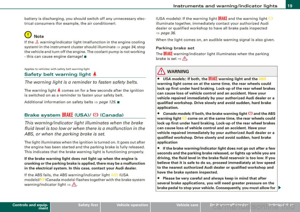
Brake system BRAKE (USA)/ (CD) (Canada)
Thi s wa rn in g/ind icator light i llumi nate s wh en the brak e
f lu id level is to o low or when t her e is a ma lfunc tion in the
ABS , or w hen the parking brake is set.
The ligh t ill umi nates whe n the igni tio n is t urned on . It goes out afte r
th e e ngine has be en started and the par king brake is fu lly released.
T his indicates that the bra ke warning light i s functioning pro perly.
If the brake warning light does not light up when the engine is
cranking or the parking brake is applied , there may be a malfunction
in the electrical system. In this case , contact your Audi dealer.
If th e ABS fai ls, the ABS warning/i ndicator light , ' (USA
m od els)/ (Ca nada mode ls) fla shes togethe r w ith the b rake sys te m
war ning/i nd icator ligh t:::::, &.
Controls and equip
ment
Instruments and warning /indi cator lights
(USA models): If the warnin g light BRAKE and the warning light
i llu min ate tog eth er, i m me dia te ly co nt ac t your author iz ed Au di
dea ler or qua lified wor kshop to have all brake pads inspected
=> page 36 .
When the li ght c omes on, a n aud ible wa rni ng sig nal i s a lso giv en.
Parking brake set
The BRAKE warnin g/indicator light i llum inates w hen the parking
brake is set:::::,& .
& WARNING
• USA models.: If both, the BRAKE warning light and the C
warning light come on at the same time , the rear wheels could
lock up first under hard braking . Lock -up of the rear wheel brakes
can cause loss of vehicle control and an accident . Have your
vehicle repaired immediately by your authorized Audi dealer or a qualified workshop . Dr ive slowly and avoid sudden , hard brake
appli cation .
• Canada models : If both, the brake warning light CCD> and the ABS
warning light ..,. come on at the same time, the rear wheels could
lock up first under hard braking . Lock -up of the rear wheel brakes
c an cause loss of vehicle control and an a ccident . Have your
vehicle repaired immediately by your authorized Audi dealer or a qualified workshop . Drive slowly and avoid sudden, hard brake
application
• If the brake warning /indicator light does not go out after a few
seconds and the parking brake released, or lights up while you are
driving, the fluid level in the brake fluid reservoir is too low . If you
believe that it is safe to do so, proceed immediately at low speed
to the nearest authorized Audi dealer or qualified workshop and
have the brake system inspected.
• Please be very careful and always keep in mind that after
several brake applications , you will need greater pressure on the
brake pedal to stop your vehi cle . Consequently , you must allow for .,_
I • •
Page 22 of 316
Instruments and warning/indicator lights
& W ARN ING (continued )
increased br aking dist ances . Trying to brake as quickly as usual
c ould lead to an a ccident. •
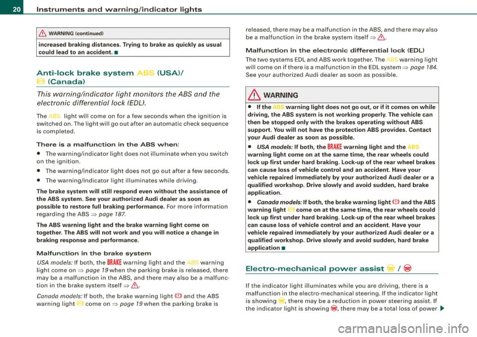
Anti-lock brake system , e (USA)/
(Canada)
T his war ning/ indic ator ligh t moni to rs the AB S and the
elect ronic diffe ren tial lock (EDL).
The J light wil l come on for a few seconds when the ignition is
swi tc hed on. The light w ill go out aft er a n aut omat ic check seque nce
is completed.
There is a malfunction in the
ABS when :
• T he warning/indicator light does not il luminate when you switch
on the ign ition.
• T he wa rning/indicator light does not go out after a few seconds.
• The wa rnin g/ind ica tor light il luminates wh ile driv in g.
The brake system will still respond even without the assistance of
the ABS system. See your authorized Audi dealer as soon as poss ible to restore full braking performan ce . For more information
regard ing the ABS ~ page 187.
The ABS warning light and the brake warning light come on
together . The ABS will not work and you will notice a change in
braking response and performance .
Malfunction in the brake system USA models: If both, t he
BRAKE warning light and the ,,[ warning
light co me on ~ page 79when the pa rking b ra ke is r eleased, there
may be a mal function in t he ABS , and t here may also be a malfunc
tion in the brake system itself ~ & .
Canada model s: If bo th, the b rake warn ing l ig ht
(Ci) and the ABS
warning light : come on~ page 79when the parking brake is released, there may be a malfunction in the ABS, and there may also
b e a ma lfunc tio n in t he b rake system itself~ & .
Malfun ction in the electronic differential lock (EDL )
T he two sys te m s ED L and ABS w ork together . The L warning ligh t
wi ll come on if there is a malfunction in the EDL system~ page 184.
See you r au thori zed A udi deale r as so on as possible.
& WARNING
• If the "warning light does not go out , or if it comes on while
driving , the ABS system is not working properly . The vehi cle can
then be stopped only with the brakes operating without ABS support . You will not have the protection ABS provides . Contact
your Audi dealer as soon as possible.
• USA models : If both , the
BRAKE w arning light and the
warning light come on at the same time, the rear wheels could lock up first under hard braking . Lock-up of the rear wheel brakes
can cause loss of vehicle control and an accident . Have your
vehicle repaired immediately by your authorized Audi dealer or a
qualified workshop. Drive slowly and avoid sudden, hard brake
appli cation .
• Canada models: If both, the brake warning light CCI» and the ABS
warning light come on at the same time , the rear wheels could
lock up first under hard braking. Lock -up of the rear wheel brakes
c an cause loss of vehi cle control and an a ccident . Have your
vehicle repaired immediately by your authorized Audi dealer or a
qualified workshop. Drive slowly and avoid sudden , hard bra ke
application •
Electro-mechanical power assist l / @
If the indicato r light i lluminates while you a re d riv ing, t here i s a
malfunction in the e lectro -mechanica l steering . If the indicator light
is showing , there may be a reduction in powe r stee ring assist. If
t h e ind icator light is show ing® , there may be a total loss o f power
~
Page 30 of 316
Driver inf ormation sy ste m
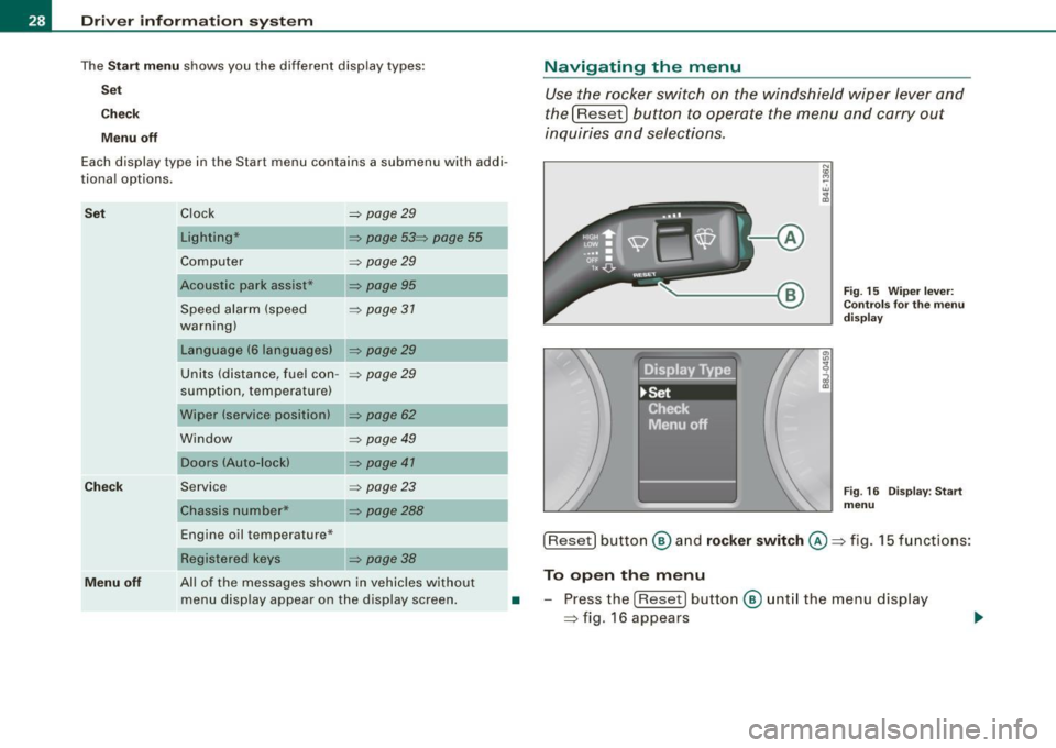
The Sta rt m enu shows you the different disp lay types:
Se t
Check
M enu off
Each display type in the Start menu contains a submenu with addi
tional options.
S et
Ch eck
Clock ~ page29
Lighting* ~ page 53~ page 55
Computer ~ page29
Acoustic park assist* ~ page95
Speed alarm (speed ~ page 37
warning)
Language (6 languages)
~ page29
Units (distance, fuel con -~ page29
sumption, temperature)
Wiper (service position)
~ page 62
Window ~ page 49
Doors (Auto-lock) ~ page 41
Service
Chassis number* ~ page23
~ page288
Navigating the menu
Use the rocker switch on the windshield wiper lever and
the[Reset) button to operate the menu and carry out
inquiries and selec tions.
-A
N
"' cc
Fig . 15 Wiper leve r:
Con trols fo r th e m enu
d is pla y
Fig . 16 Disp lay: Start
menu
Engine oil temperature* ___ __, [Reset] button ® an d rock er swit ch @ => fig. 15 functions:
Menu off
Registered keys ~ page 38
All of the messages shown in vehicles without
menu display appear on the display screen. To open the menu
• -Press the [Reset ) button ® unt il the menu display
=> fig. 16 appears
Page 33 of 316
- Press the knob button:::> page 30, fig. 19 until the
=>
page 30, fig. 18 symbol appears.
Resetting the maximum speed
- Drive the vehicle at a speed of at least 3 mph (5 km/h)
- Press the knob for more than 2 seconds .
The speed warning symbol ~ (USA models) /~ (Canada models) will
appear briefly in the display when you release the button to indicate
that the maximum speed has been stored successfully.
The maximum speed remains stored until it is changed by pressing
the button again briefly or un til it is del ete d by a l engthy push on the
button. •
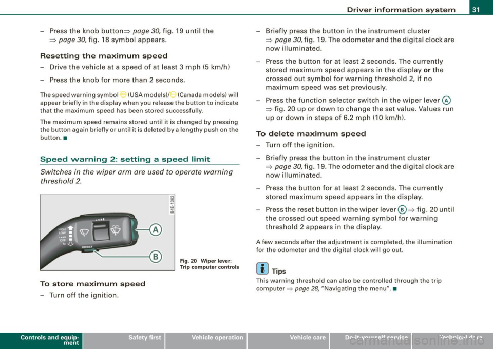
Speed warning 2: setting a speed limit
Switches in the wiper arm are used to operate warning
threshold 2 .
To store maximum speed
- Turn off the ignition.
Con tro ls and eq uip
ment
A
Fig . 20 Wiper lever:
Trip computer controls
Driver information system
- Briefly press the button in the instrument cluster
=;, page 30, fig. 19. The odometer and the digital clock are
now illuminated.
- Press the button for at least 2 seconds. The currently
stored maximum speed appears in the display
or the
crossed out symbol for warning threshold 2, if no maximum speed was set previously.
- Press the function selector switch in the wiper lever @
::::> fig. 20 up or down to change the set value. Values run
up or down in steps of 6.2 mph (10 km/h).
To delete maximum speed
- Turn off the ignition.
- Briefly press the button in the instrument cluster
=>
page 30, fig. 19. The odometer and the digital clock are
now illuminated .
- Press the button for at least 2 seconds. The currently
stored maximum speed appears in the display.
Press the reset button in the wiper lever ®=> fig. 20 until
the crossed out speed warning symbol for warning threshold 2 appears in the display.
A few seconds after the adjustment is completed , the illumination
for the odometer and the digital clock will go out.
[ i] Tips
Th is warning threshold can also be controlled through the trip
computer =>
page 28, "Navigating the menu". •
Vehicle care I I irechnical data