engine AUDI TT COUPE 2014 Owners Manual
[x] Cancel search | Manufacturer: AUDI, Model Year: 2014, Model line: TT COUPE, Model: AUDI TT COUPE 2014Pages: 284, PDF Size: 34.42 MB
Page 251 of 284
Downloaded from www.Manualslib.com manuals search engine N
....
Lfl
N
Lfl
.... Starting
the engine
The jump leads must be connected in the correct
sequence.
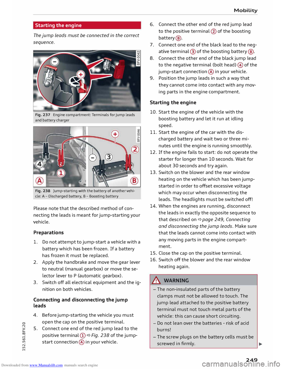
Fig. 237 Engine compartment: Terminals for jump leads
and battery charger
Fig. 238 Jump-starting with the battery of another vehi
cle: A -Discharged battery, B -Boosting battery
Please note that the described method of con
necting the leads is meant for jump-starting your
vehicle.
Preparations
1. Do not attempt to jump-start a vehicle with a
battery which has been frozen. If a battery
has frozen it must be replaced.
2. Apply the handbrake and move the gear lever
to neutral (manual gearbox) or move these
lector Lever to P (automatic gearbox).
3. Switch off all electrical equipment and the ig-
nition on both vehicles.
Connecting and disconnecting the jump
leads
4.
5. Before
jump-starting the vehicle you must
open the cap on the positive terminal.
Connect one end of the red jump lead to the
positive terminal (!) ¢Fig. 238 ofthejump
start connection @ in your vehicle. Mobility
6. Connect
the other end of the red jump lead
to the positive terminal @ofthe boosting
battery @.
7. Connect one end of the black lead to the neg
ative terminal@ of the boosting [email protected] the other end of the black jump lead
to the negative terminal (bolt head) © of the
jump-start connection@ in your vehicle.
9.
Position the jump leads in such a way that
they cannot come into contact with any mov
ing parts in the engine compartment.
Starting the engine
10. Start the engine of the vehicle with the
boosting battery and let it run at idling
speed.
11. Start the engine of the car with the dis
charged battery and wait two or three mi
nutes until the engine is running smoothly.
12. If the engine fails to start: do not operate the
starter for longer than 10 seconds. Wait for
about 30 seconds and try again.
13. Switch
on the blower and the rear window
heating on the vehicle which has been jump
started in order to offset excessive voltage
which may occur when disconnecting the
leads. The headlights must be switched off!
14. When the engines are running, disconnect
the leads in exactly the opposite sequence to
that described on¢ page 249, Connecting
and disconnecting the jump leads. Make sure
that the leads cannot come into contact with
any moving parts in the engine compart
ment.
15. Close the cap on the positive terminal.
16. Switch off the blower and the rear window
heating again.
_& WARNING
- The non-insulated parts of the battery
clamps must not be allowed to touch. The
jump lead attached to the positive battery
terminal must not touch metal parts of the
vehicle: this can cause short circuiting.
- Do not lean over the batteries -risk of acid
burns!
- The screw plugs on the battery cells must be
screwed in firmly.
.,..
249
Page 252 of 284
Downloaded from www.Manualslib.com manuals search engine Mobility
- Keep sparks, flame and lighted cigarettes
away from batteries: the gases given off can
cause an explosion.
- If jump-starting another vehicle, position
the jump Leads in such a way that they can
not come into contact with any moving
parts in the engine compartment of the oth
er vehicle.
CD CAUTION
Please note that the above method of con
necting the Leads is intended for jump-start
ing your vehicle. If jump-starting another ve
hicle, you should not connect the negative
lead (-) to the negative terminal of the dis
charged battery, but directly to the engine
block or a solid metal part bolted to the en
gin e block. If the battery of the other vehicle
does not have a gas vent, there is a risk that a
mixture of oxygen and hydrogen gas can accu
mulate and cause an explosion.
@ Note
- The battery is vented to the outside to pre
vent gases entering the vehicle's interior.
- Connect the battery clamps so they have
good metal-to-metal contact with the bat
tery terminals.
Tow-starting / towing
away
General notes
Some experience is required to tow or tow-start a
vehicle, especially when using a tow-rope. Both
drivers should be familiar with the technique re
quired for towing. Inexperienced drivers should
not attempt to tow-start or tow away another ve
hicle.
Do not pull too hard with the towing vehicle and
take care to avoid jerking the tow-rope. When
towing off-road, there is always a risk that the
anchorage points may be overloaded.
Tow-bar / tow-rope
It is easier and safer to tow the vehicle with a
tow-bar. You should only use a tow-rope if you do
250 not
have a tow-bar. It is advisable to use a tow
rope made of elastic synthetic fibre or similarly
elastic material.
Notes on towing vehicles
The vehicle can be towed with a tow-bar or tow
rope. When the engine is not running, the gear
box will not be adequately Lubricated if the fol
lowing speed/distance restrictions are not ob
served:
- The vehicle must not be towed faster than
SO km/h.
- The vehicle must not be towed further than
50km.
Additi onal notes on towing by breakdown
truck
If one of the axles has to be raised in order to tow
the vehicle, please refer to the following table to
determine the appropriate axle for your gearbox/
drive combination:
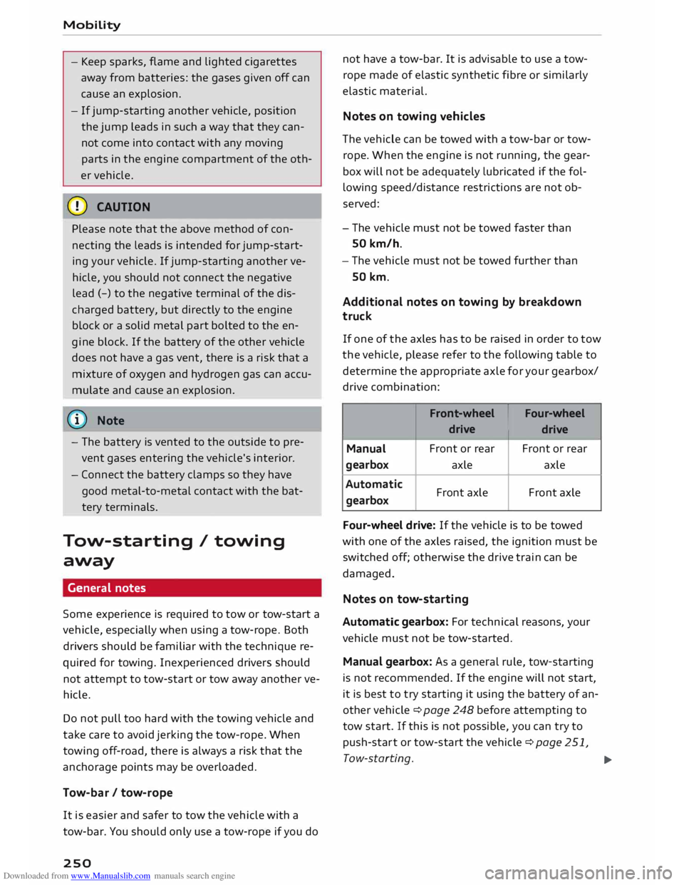
Front-wheel IFour-wheel
drive drive
Manual Front
or rear Front or rear
gearbox axle
axle
Automatic gearbox Front
axle Front axle
Four-wheel drive: If the vehicle is to be towed
with one of the axles raised, the ignition must be
switched off; otherwise the drive train can be
damaged.
Notes on tow-starting
Automatic gearbox: For technical reasons, your
vehicle must not be tow-started.
Manual gearbox: As a general rule, tow-starting
is not recommended. If the engine will not start,
it is best to try starting it using the battery of an
other vehicle ¢ page 248 before attempting to
tow start. If this is not possible, you can try to
push-star t or tow-start the vehicle ¢ page 251,
Tow-starting. ...,
Page 253 of 284
Downloaded from www.Manualslib.com manuals search engine 0
N
co
....
\D U'l ,&.
WARNING
There is a high risk of accidents when towing/
tow-starting, as the towed vehicle can easily
be driven into the towing vehicle.
CD CAUTION
- If it is not possible to tow the vehicle as de
scribed above (e.g. due to a gearbox failure
or if the vehicle has to be towed further
than 50 km), it must be transported on a
special car transporter or trailer.
- To wing a vehicle with the wrong axle raised
can cause serious damage to the gearbox.
@ Note
- Automatic gearbox: It is not possible to
move the selector lever out of position P if
the electrical power supply fails. Before the
vehicle can be recovered/manoeuvred you
must manually release the selector lever
¢page 78.
- Please observe the relevant regulations
when towing or tow-starting.
Towing away
Please observe the important safety warnings on
¢page 250.
Preparations
.. Attach the tow-rope or the tow-bar only to the
towing anchorages provided for this purpose
¢page 252, ¢page 252.
.. Please ensure that the tow-rope is not twisted
as it could otherwise become unscrewed from
the towline anchorage while the vehicle is being
towed.
.. The hazard warning lights of both vehicles
must normally be switched on ¢ page 40. How
ever, observe any regulations to the contrary.
Towing vehicle (front)
.. Ensure that the tow-rope is taut before you
drive off.
N
� l
l
Important: The battery must be adequately charged. Mobility
.. Engage the clutch very gently when starting to
move (manual gearbox) and press the accelera
tor slowly.
.. Avoid unnecessary braking and manoeuvres.
Vehicle being towed (rear)
.. Ensure
that the ignition is switched on, the
steering wheel is not locked, and that you can
operate the turn signals, horn or windscreen
wipers if
necessary ¢,& .
.. The
brake servo only works when the engine is
running. The power steering only works when
the ignition is on and the vehicle is moving 1
).
Otherwise you will need to press the brake ped
al significantly harder and apply more force to
move the steering wheel.
.. Please ensure that the steering wheel is un-
locked and that it moves freely.
.. Release
the parking brake ¢page 66.
.. Manual gearbox: Put the gear lever in neutral.
.. Automatic gearbox: Move the selector lever to
position N.
.. Ensure
that the tow-rope remains taut at all
times when towing.
,&. WARNING
If the vehicle has no electrical power, do NOT
use a tow-bar or tow-rope to tow the vehicle
@ Note
You can use the turn signals to indicate a
change of direction (or lane) even when the
hazard lights are on. The hazard lights will be
interrupted temporarily .
Tow-starting
Please observe the important safety warnings on
¢page 250.
Important: Your vehicle must be fitted with a
manual gearbox. If your vehicle has a petrol en
gine, it must not be towed further than SO me-
tres ¢(D.
.,.
251
Page 254 of 284
Downloaded from www.Manualslib.com manuals search engine Mobility
..
Attach the tow-rope or the tow-bar only to the
towing anchorages provided for this purpose
¢page 252, ¢page 252 .
.. Engage second or third gear before moving off.
.. Press the clutch and hold the pedal down .
.. Switch
on the ignition.
.. Once both vehicles are moving, release the
clutch.
"'As soon as the engine starts, press the clutch
pedal and put the gear lever in neutral.
CD CAUTION
When tow-starting the vehicle, do not tow it
further than SO metres; otherwise the cata
lytic converter could be damaged.
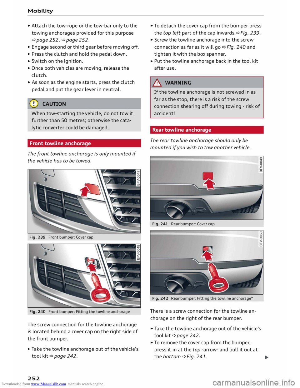
Front towline anchorage
The front towline anchorage is only mounted if
the vehicle has to be towed.
Fig. 239 Front bumper: Cover cap
Fig. 240 Front bumper: Fitting the towline anchorage
The screw connection for the towline anchorage
is located behind a cover cap on the right side of
the front bumper.
.. Take the towline anchorage out of the vehicle's
tool kit ¢ page 242.
252 ..
To detach the cover cap from the bumper press
the top left part of the cap inwards ¢ Fig. 239.
.. Screw the towline anchorage into the screw
connection as far as it will go¢ Fig. 240 and
tighten it with the box spanner .
.. Put
the towline anchorage back in the tool kit
after use .
A WARNING
If the towline anchorage is not screwed in as
far as the stop, there is a risk of the screw
connection shearing off during towing -risk of
accident!
Rear towline anchorage
The rear towline anchorage should only be
mounted if you wish to tow another vehicle.
Fig. 241 Rear bumper: Cover cap
Fig. 242 Rear bumper: Fitting the towline anchorage*
There is a screw connection for the towline an
chorage on the right of the rear bumper. a,
.. Take the towline anchorage out of the vehicle's
tool kit ¢ page 242.
"'To remove the cover cap from the bumper,
press it in at the top -arrow- and pull it out at
the bottom ¢ Fig. 241.
..,.
Page 255 of 284
Downloaded from www.Manualslib.com manuals search engine 0
N
co
....
\D U'l
N
U'l
.... ...
Screw the towline anchorage into the screw
connection as far as it will go¢ Fig. 242 and
tighten it with the box spanner .
... Put the towline anchorage back in the tool kit
after use.
A WARNING
If the towline anchorage is not screwed in as
far as the stop, there is a risk of the screw
connection shearing off during towing -risk of
accident! Mobility
253
Page 256 of 284
Downloaded from www.Manualslib.com manuals search engine Fuses
and bulbs
Fuses and bulbs
Fuses Fuses in vehic le interior
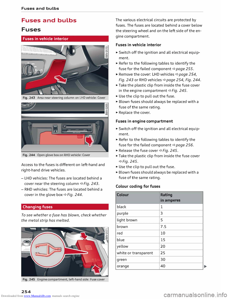
Fig. 243 Area near steering column on LHD vehicle: Cover
Fig. 244 Open glove box on RHO vehicle: Cover
Access to the fuses is different on left-hand and
right-hand drive vehicles.
- LHD vehicles: The fuses are located behind a
cover near the steering column ¢Fig. 243.
- RHD vehicles: The fuses are located behind a
cover in the glove box¢ Fig. 244.
Changing fuses
To see whether a fuse has blown, check whether
the metal strip has melted.
Fig. 245 Engine compartment, left-hand side: Fuse cover
254 The
various electrical circuits are protected by
fuses. The fuses are located behind a cover below
the steering wheel and on the left side of the en
gine compartment.
Fuses in vehicle interior
.. Switch
off the ignition and all electrical equip
ment .
.. Refer to the following tables to identify the
fuse for the failed component ¢ page 255 .
.. Remove the cover: LHD vehicles c:> page 254,
Fig. 243 or RHD vehicles ¢ page 254, Fig. 244 .
.. Take the plastic clip from inside the fuse cover
in the engine compartment ¢ Fig. 245 .
.. Use the clip to pull out the fuse.
.. Blown fuses should always be replaced with a
fuse of the same rating .
.. Replace the cover.
Fuses in engine compartment
.. Switch off the ignition and all electrical equip
ment .
.. Refer to the following tables to identify the
fuse for the failed component ¢ page 256 .
.. Release the fuse cover ¢ Fig. 245.
.. Take the plastic clip from inside the fuse cover
¢Fig. 245.
.. Use the clip to pull out the fuse.
.. Blown fuses should always be replaced with a
fuse of the same rating.
Colour coding for fuses
Colour Rating
in amperes
black 1
purple 3
light brown 5
brown 7.5
red 10
blue 15
yellow 20
white or transparent 25
green 30
orange 40
Page 257 of 284
Downloaded from www.Manualslib.com manuals search engine 0
N
co
....
\D L/'l
N
L/'l
.... ,&.
WARNING
Never attempt to repair a fuse or replace a
blown fuse by fitting a fuse with a higher am
pere rating. This could damage the electrical
system -risk of fire!
CD CAUTION
If a newly replaced fuse blows again after a
short time, the electrical system must be
checked by a qualified workshop as soon as
possible.
@ Note
- Unassigned fuse locations are not shown in
the tables below.
- Some of the items of equipment listed in
the tables below are only fitted on certain
models or are optional extras.
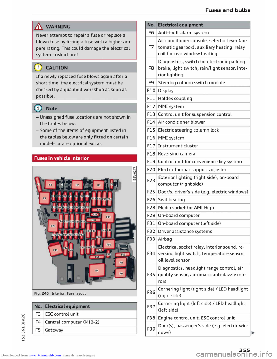
Fuses in vehicle interior
Fig. 246 Interior: Fuse layout
No. Electrical
equipment
F3 ESC
control unit
F4 Central computer (MIB-2)
FS Gateway No.
F6
F7
F8 F9
FlO Fll
F12
F13
F14
FlS
F16
F17
F18
Fl9
F20
F23
F25
F26
F28
F29
F31
F32 F33
F34
F35
F36 F37
F38 F39 Fuses
and bulbs
Electrical equipment
Anti-theft alarm system
Air conditioner console, selector lever (au-
tomatic gearbox), auxiliary heating, relay
coil for rear window heating
Diagnostics, switch for electronic parking
brake, light switch, rain/light sensor, inte-
rior lighting
Steering column switch module
Display
Haldex coupling
MMI system
Control unit for suspension control
Air conditioner blower
Electric steering column lock
MMI system
Instrument cluster
Reversing camera
Control unit for convenience key system
Electric lumbar support adjuster
Exterior lighting (right side), on-board
computer (right side)
Door/s, driver's side (e.g. electric windows)
Seat heating
Media socket for AMI High
On-board computer
On-board computer (left side)
Driver assistance systems
Airbag Electrical socket relay, interior sound, re-
versing light switch, temperature sensor,
oil level sensor
Diagnostics, headlight range control, air
quality sensor, automatic anti-dazzle mir-
rors
Corn ering light (right side)/ LED headlight
(right side)
Cornering light (left side) / LED headlight
(left side)
Engine control unit, ESC control unit
Door(s), passenger's side (e.g. electric win-
dows)
255
Page 258 of 284
Downloaded from www.Manualslib.com manuals search engine Fuses
and bulbs
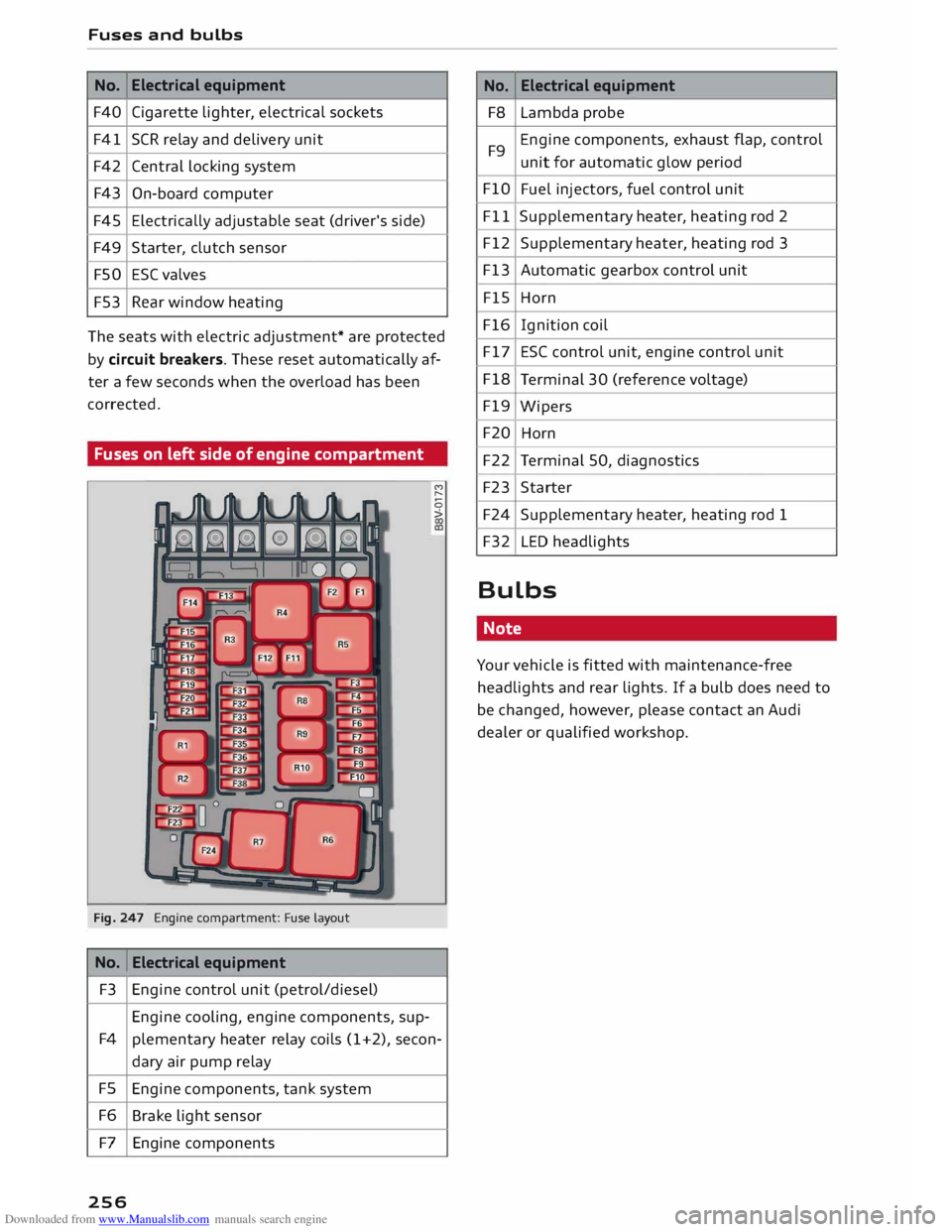
No. Electrical
equipment
F40 Cigarette lighter, electrical sockets
F41 SCR relay and delivery unit
F42 Central locking system
F43 On-board computer
F45 Electrically
adjustable seat (driver's side)
F49 Starter, clutch sensor
FSO ESC
valves
F53 Rear window heating
Th e seats with electric adjustment* are protected
by circuit breakers. These reset automatically af
ter a few seconds when the overload has been
corrected.
Fuses on left side of engine compartment
Fig. 247 Engine compartment: Fuse la
yout
No. Electrical
equipment
F3 Engine control unit (petrol/diesel)
Engine cooling, engine components, sup-M
,...,
0
>
F4 plementary heater relay coils (1+2), secon-
dary air pump relay
FS Engine components, tank system
F6 Brake light sensor
F7 Engine components
256 No.
Electrical
equipment
F8 Lambda probe
F9 Engine
components, exhaust flap, control
unit for automatic glow period
FlO Fuel injectors, fuel control unit
Fll Supplementary
heater, heating rod 2
F12 Supplementary heater, heating rod 3
F13 Automatic gearbox control unit
FlS Horn
F16 Ignition coil
F17 ESC control unit, engine control unit
F18 Terminal 30 (reference voltage)
F19 Wipers
F20 Horn
F22 Terminal 50, diagnostics
F23 Starter
F24 Supplementary heater, heating rod 1
F32 LED headlights
Bulbs Note
Your vehicle is fitted with maintenance-free
headlights and rear lights. If a bulb does need to
be changed, however, please contact an Audi
dealer or qualified workshop.
Page 259 of 284
Downloaded from www.Manualslib.com manuals search engine 0
N
co
....
\D L/'l
N
L/'l
.... Technical
data
Vehicle identification
data
XXXXX XX · X · XXXX XXX
/1\...l_ FAHRZG. -10£NT · NR.
� VBIICI.E -ll£NT. NO. xx
p /TYPE XXXXXXXX
XX X XXXXXXXX
XXX XXX
XX XXXXXXX XX X.X XX
XXX KW
XXX ('5\_J_
MOTO
RKB ./GETR.KB
.
xxxx XXX
XXX \::1/1
1 £NG.COO£/TRANS. COO£
(A\_J_ lAO(NR./INNENAUSST.
� PAINTNO
./WT
£R IO
R
xxxx / xxxx
XXX / xx
M
. ·
AUSST. / OPTIONS
EOA 7D5
2EH J02
3FC
FOA
TL6 3KA
lXW
7T6 CV7
3L4
15A 4UB
6XM 55G
1LB lAS
5MU 7X1
9G3 OG7 OYH
8EH UlA X9B
803 908 824
7KO 4X3 2K2
4KC 3YO 413
7GB 01A 5RW
1BA
OJF 027
D2D
5D2 4GO
@ f----- XX.
X XX.X XX.X XXXX
Fig. 248 Vehicle data sticker
Vehicle identification number a,
a,
.....
0
"
The vehicle identification number can be found
on the infotainment system, on the vehicle data
sticker and behind the windscreen on the driver's
side*. The chassis number is also located on the
rear panel in the engine compartment*.
Type plate
The type plate is located in the engine compart
ment. Vehicles for certain export countries have
no type plate.
Vehicle data sticker
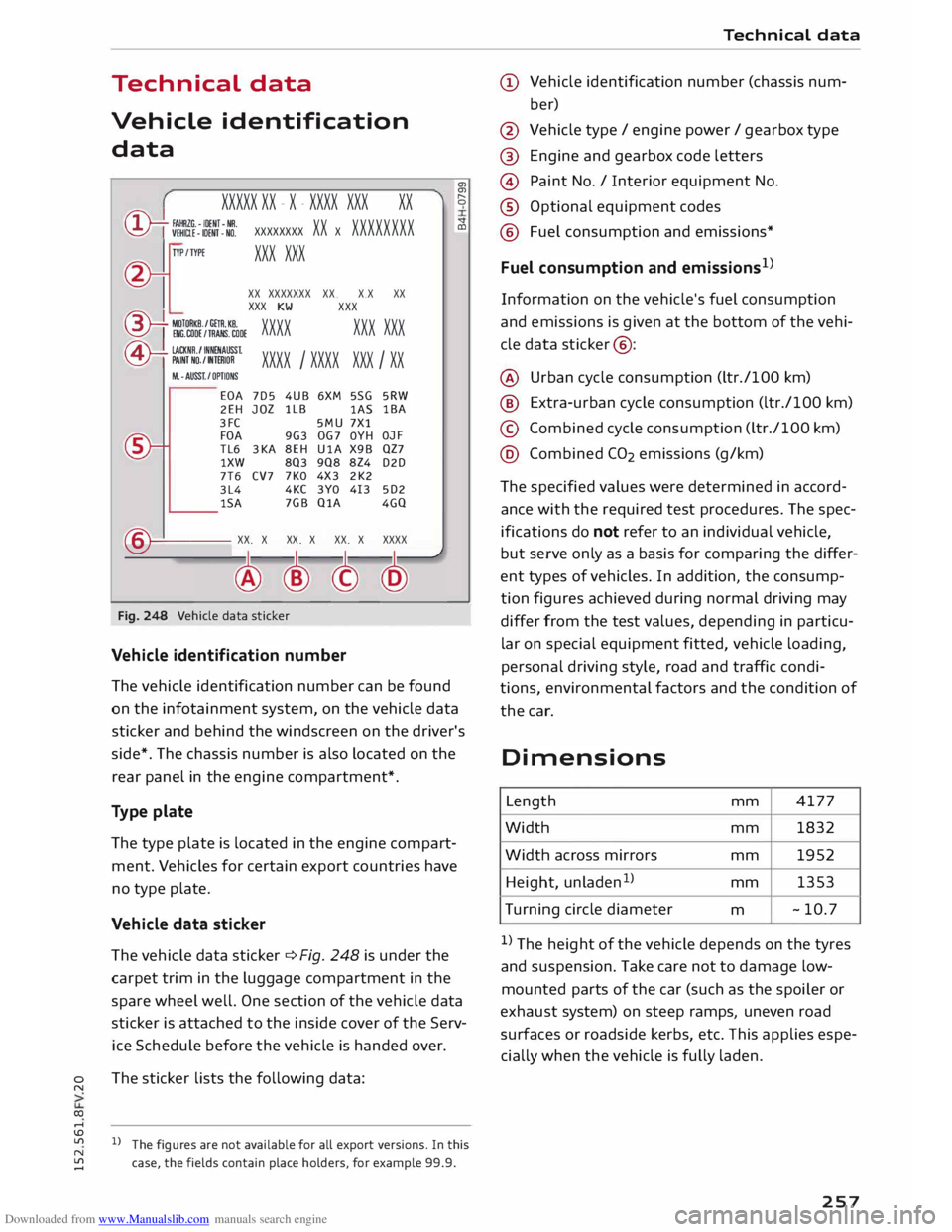
The vehicle data sticker ¢ Fig. 248 is under the
carpet trim in the luggage compartment in the
spare wheel well. One section of the vehicle data
sticker is attached to the inside cover of the Serv
ice Schedule before the vehicle is handed over.
The sticker lists the following data:
l l
The figures are not available for all export versions. In this
case, the fields contain place holders, for example 99.9. Technical
data
(D Vehicle identification number (chassis num-
ber)
@ Vehicle type/ engine power/ gearbox type
@ Engine and gearbox code letters
© Paint No./ Interior equipment No.
® Optional equipment codes
® Fuel consumption and emissions*
Fuel consumption and emissions 1
>
Information on the vehicle's fuel consumption
and emissions is given at the bottom of the vehi
cle data sticker @:
@ Urban cycle consumption (ltr./100 km)
@ Extra-urban cycle consumption (ltr./100 km)
© Combined cycle consumption (ltr./100 km)
@ Combined CO2 emissions (g/km)
The specified values were determined in accord
ance with the required test procedures. The spec
ifications do not refer to an individual vehicle,
but serve only as a basis for comparing the differ
ent types of vehicles. In addition, the consump
tion figures achieved during normal driving may
differ from the test values, depending in particu
lar on special equipment fitted, vehicle loading,
personal driving style, road and traffic condi
tions, environmental factors and the condition of
the car.
Dimensions Length mm 4177
Width mm 1832
Width across mirrors mm 1952
Height, unladen 1
>
mm 1353
Turning circle diameter
m -10.
7
I) The height of the vehicle depends on the tyres
and suspension. Take care not to damage low
mounted parts of the car (such as the spoiler or
exhaust system) on steep ramps, uneven road
surfaces or roadside kerbs, etc. This applies espe
cially when the vehicle is fully laden.
257
Page 260 of 284
Downloaded from www.Manualslib.com manuals search engine Technical
data
Capacities Fuel tank
- Front-wheel drive ltr. - so
- Four-wheel drive ltr. -
55
Windscreen and headlight ltr.
-4.0
washer system*
Explanation of technical
data
The figures for some markets can vary due to dif
ferent export versions and test procedures.
Please note that the
details
listed in the vehicle's
registration documents can be taken as correct.
Performance figures
The performance figures were measured without
equipment which may influence performance,
such as mudflaps or extremely wide-section
tyres.
Kerb weight (unladen weight)
For Europe and certain other markets: the kerb
weight includes an allowance of 75 kg for the
driver in accordance with EU Regulation
1230/2012.
Notes for following tables
MG = Manual gearbox I AG = Automatic gearbox
l) Maximum speed is achieved in the second
highest gear.
2 ) This engine is available with reduced power for
some markets (see car documentation). The per
formance figures may be slightly different.
258