display AUDI TT COUPE 2017 Owners Manual
[x] Cancel search | Manufacturer: AUDI, Model Year: 2017, Model line: TT COUPE, Model: AUDI TT COUPE 2017Pages: 322, PDF Size: 79.73 MB
Page 5 of 322
co
co
.... N
" N .... 0
0
Vl c:o
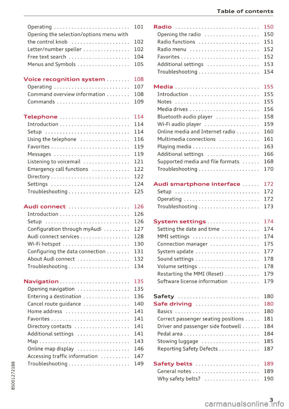
Operating . . . . . . . . . . . . . . . . . . . . . . . . . . 101
Opening the selection/options menu with
the control knob . . . . . . . . . . . . . . . . . . . . 102
Letter/number speller . . . . . . . . . . . . . . . . 102
Free text search . . . . . . . . . . . . . . . . . . . . . 104
Menus and Symbols . . . . . . . . . . . . . . . . . . 105
Voice recognition system . . . . . . . . 108
Operating . . . . . . . . . . . . . . . . . . . . . . . . . . 107
Command overview information . . . . . . . . 108
Commands . . . . . . . . . . . . . . . . . . . . . . . . . 109
Telephone . . . . . . . . . . . . . . . . . . . . . . . . 114
Introduction . . . . . . . . . . . . . . . . . . . . . . . . 114
Setup . . . . . . . . . . . . . . . . . . . . . . . . . . . . . 114
Using the telephone . . . . . . . . . . . . . . . . . 116
Fa vorites . . . . . . . . . . . . . . . . . . . . . . . . . . . 119
Messages . . . . . . . . . . . . . . . . . . . . . . . . . . 119
Listening to voicemail . . . . . . . . . . . . . . . . 121
Emergency call functions . . . . . . . . . . . . . 122
Directory . . . . . . . . . . . . . . . . . . . . . . . . . . . 122
Se ttings . . . . . . . . . . . . . . . . . . . . . . . . . . . 124
Troubleshooting . . . . . . . . . . . . . . . . . . . . . 125
Audi connect . . . . . . . . . . . . . . . . . . . . . 126
Introduction . . . . . . . . . . . . . . . . . . . . . . . . 126
Setup . . . . . . . . . . . . . . . . . . . . . . . . . . . . . 126
Configuration through myAudi . . . . . . . . . 127
Audi connect services . . . . . . . . . . . . . . . . . 128
W i-F i hotspot . . . . . . . . . . . . . . . . . . . . . . . 130
Configur ing the data connect ion . . . . . . . . 131
About Audi connect . . . . . . . . . . . . . . . . . . 132
Troubleshooting . . . . . . . . . . . . . . . . . . . . . 134
N .
. av1gat1on .. ............... .. .... . 135
Opening navigation . . . . . . . . . . . . . . . . . . 135
Ent ering a d estination . . . . . . . . . . . . . . . . 136
Cancel route gu idance . . . . . . . . . . . . . . . . 140
Home address . . . . . . . . . . . . . . . . . . . . . . 141
Favorite s . . . . . . . . . . . . . . . . . . . . . . . . . . . 141
Directory contacts . . . . . . . . . . . . . . . . . . . 141
Addit ional settings . . . . . . . . . . . . . . . . . . 141
Map ..... ... ................... ... . 143
Online map display . . . . . . . . . . . . . . . . . . 146
Accessing traffic information . . . . . . . . . . 147
Troubleshooting . . . . . . . . . . . . . . . . . . . . . 149
Table of contents
Radio ...... .. .. .................. .
150
Opening the radio . . . . . . . . . . . . . . . . . . . 150
Radio funct ions . . . . . . . . . . . . . . . . . . . . . 151
Rad io menu . . . . . . . . . . . . . . . . . . . . . . . . 152
Favorites . . . . . . . . . . . . . . . . . . . . . . . . . . . 152
Additional settings . . . . . . . . . . . . . . . . . . 153
Troubleshooting . . . . . . . . . . . . . . . . . . . . . 154
Med ia ..... ... .. ... ........... ... .. 155
Introduction ... .. .. .... ..... .... .. .. 155
Notes . . . . . . . . . . . . . . . . . . . . . . . . . . . . . 155
Media drives . . . . . . . . . . . . . . . . . . . . . . . . 156
Bluetooth audio player . . . . . . . . . . . . . . . 158
Wi-Fi audio player . . . . . . . . . . . . . . . . . . . 159
Online media and Internet radio . . . . . . . . 160
Multimedia connections . . . . . . . . . . . . . . 161
Playing media . . . . . . . . . . . . . . . . . . . . . . . 163
Additional settings . . . . . . . . . . . . . . . . . . 166
Supported medi a and file formats . . . . . . 168
T roubleshooting . . . . . . . . . . . . . . . . . . . . . 170
Audi smartphone interface . . . . . . 172
Setup . . . . . . . . . . . . . . . . . . . . . . . . . . . . . 172
Operating . . . . . . . . . . . . . . . . . . . . . . . . . . 172
Troubleshooting . . . . . . . . . . . . . . . . . . . . . 173
System settings .................. 174
Settingthedateandtime ............. 174
MM isettings .. .. .. .......... ....... 174
Connection manager . . . . . . . . . . . . . . . . . 175
System update . . . . . . . . . . . . . . . . . . . . . . 177
Sound settings . . . . . . . . . . . . . . . . . . . . . . 178
Vo lume settings . . . . . . . . . . . . . . . . . . . . . 178
Restarting th e MMI (Reset) . . . . . . . . . . . . 179
Softw are license information 179
Safety ..... .. .. .. ............... .. 180
Safe driving . . . . . . . . . . . . . . . . . . . . . . 180
Basi cs . . . . . . . . . . . . . . . . . . . . . . . . . . . . . 180
Cor rec t passenger sea ting positions . . . . . 181
Driver and passenger side footwell . . . . . . 184
Pedal area . . . . . . . . . . . . . . . . . . . . . . . . . . 184
Stowing luggage . . . . . . . . . . . . . . . . . . . . 185
Reporting Safety Defects . . . . . . . . . . . . . . 187
Safety belts . . . . . . . . . . . . . . . . . . . . . . 189
General notes . . . . . . . . . . . . . . . . . . . . . . . 189
Why safety belts? . . . . . . . . . . . . . . . . . . . 190
3
Page 9 of 322
co
co
.... N
" N .... 0
0
Vl c:o
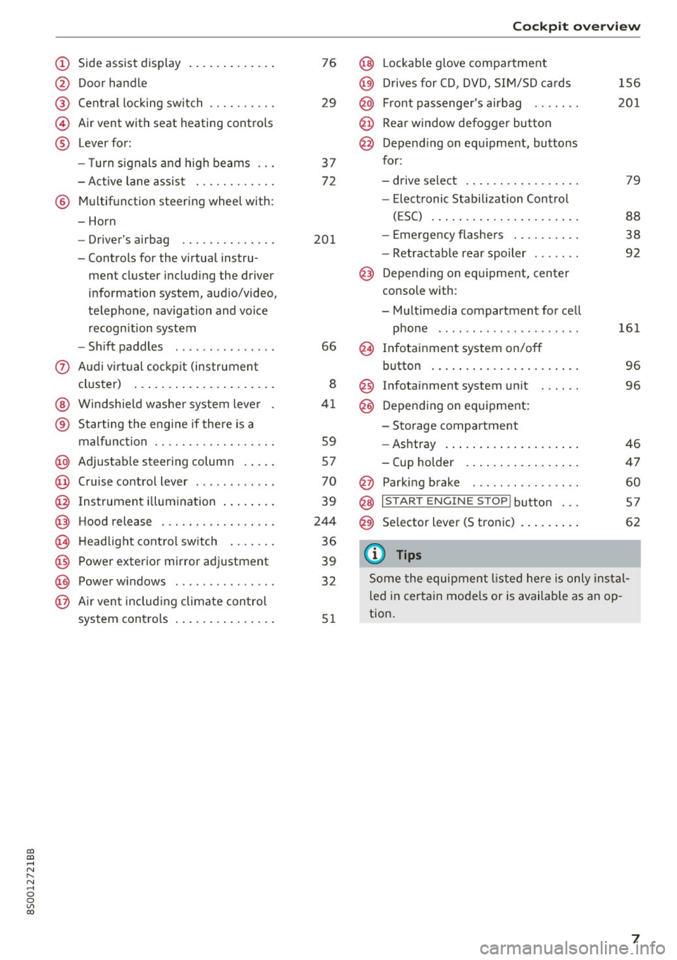
(!) Side assist display ..... ... .. .. .
@ Door handle
®
©
®
Cent ral locking switch
Air vent with seat heating controls
Lever for:
- T urn s ignals and h igh beams .. .
- Active lane assis t ......... .. .
® Multifunction steering wheel with :
- Horn
- Driver's ai rbag .. ......... .. .
- Controls for the virtual instru-
ment cluster includ ing the driver
information system, aud io/video,
telephone, navigation and voice
recogn ition system
- Shift paddles . .... ..... ... . .
0 Aud i v ir tu al co ckpit (instrument
cluster) ... .... .. .... ... .. .. .
@ W indshield washer system lever
® S tarting the engi ne if the re is a
mal func tion .. ........... .. .. .
@ Adjustab le st eering column . ... .
@ Cruise co ntrol lever .. ..... ... . .
@ Ins trument i llum ination ... .. .. .
@ Hood release . .... ......... .. .
0 H eadlight cont rol sw itch .... .. .
@ Power exterior mirror adjustment
@ Power windows . .... ..... ... . .
@ A ir ven t incl uding climate con trol
system controls ... .... ... .. .. .
76
29
3 7
72
201
66
8
41
59
57
70
39
244
36
39
32
5 1
Coc kpit o ve rv iew
@ Lockable glove compartment
@) Drives for CD, DVD, SIM/SD cards
@ Front passenge r's airbag ...... .
@ Rear window defogg er button
@ Depend ing o n equ ipment, buttons
for :
- drive select .. ... .. .. ..... .. .
- Elect ronic S tabilization Control
( E SC) ... .. .. .. .... . ..... .. .
- E me rgency flashe rs ...... ... .
- Retractab le rear spoiler ...... .
@) Depending on eq uipment, center
console with :
- Multimedia compartment for cell phone ...... .. ............ .
@ Infotainment system on/off
button ... .. .. ... .. .. ..... .. .
@ Infotai nment system unit
@) Depend ing o n eq uipment:
- Storage compartment
- Ashtray ... .. ... .. .. ..... .. .
- Cup holder .. ... .. .. ..... .. .
@ Parking brake . .. ............ .
@ I START E NGINE STOP I button ...
@) Selector lever (S tronic)
(D Tips
156
2 01
79
88
38
92
161 96
96
46
4 7
60
5 7
62
Some the equipment listed he re is only ins tal
l e d in certa in models or is available as an op
tion.
7
Page 10 of 322
Instrumen ts and ind icator ligh ts
Instruments and indicator Lights
Instruments
Audi virtual cockpit (instrument cluster)
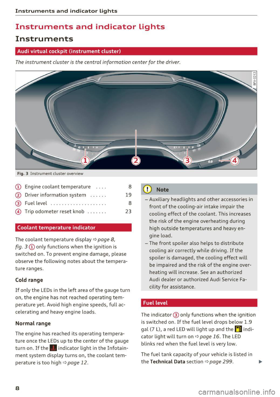
The instrument cluster is the central information center for the driver.
Fig. 3 Instrume nt cluster overv iew
(D Eng ine coolant temperature 8
@ Driver information system . . . . . . 19
® Fuel level . . . . . . . . . . . . . . . . . . . . 8
@ Trip odometer reset knob . . . . . . . 23
Coolant temperature indicator
The coolan t temperature display c:> page 8,
fig. 3
(D only functions when the ignition is
switched on. To prevent engine damage, p lease
observe the following notes about the tempera
ture ranges.
Cold rang e
If o nly the L EDs in the left area of the gauge turn
on, the engine has not reached operating tem
perature yet. Avoid high engine speeds, full ac
celerating and heavy engine loads .
Normal range
The engine has reached its operating tempera
ture once the LEDs up to the center of the gauge
turn on . If the . indicator light in the Infotain
ment system display turns on, the coolant tem
perature is too high
c:> page 12.
8
(D Note
-Aux iliary head lights and other accessories in
front of the coo ling-a ir intake impa ir the
cooling effect o f the coolant. This increases
the risk of the engine overheating during high outside temperatures and heavy en
gine load.
- T he front spoiler a lso helps to distribute
cooling air correctly while driving . If the
spoiler is damaged, the cooling effect will
be impaired and the risk of the eng ine over
heating w ill increase. See an authorized
Audi dealer or author ized Audi Service Fa
cility for assistance .
Fuel level
The indicator @ only func tions when the ignition
i s sw itched on. If the fuel level drops below 1.9
gal (7
L), a red LED wi ll light up and the rD indi
cator light will turn on
c:> page 16 . The LED
blinks red when the fuel level is very low.
The fuel tank capacity of your veh icle is listed in
the
Techni cal Dat a sectio n c:> page 299. ..,_
Page 11 of 322
co
co
.... N
" N .... 0
0
Vl c:o
(D Note
Never drive until the tank is completely emp
ty. The irregular supply of fuel that results
from that can cause engine misfires . Uncom
busted fuel will then enter the exhaust sys
tem. This can cause overheating and damage
to the catalytic converter .
Indicator lights
Description
The indicator lights in the instrument cluster
blink or turn on. They indicate functions or mal
functions.
With some indicator lights, messages may appear and warning signals may sound. The indica
tor lights and messages in the display can be cov
ered by other displays. To show them again, se lect the tab for the indicator lights and messages
using the multifunction steering wheel
c;, page 19. If there are several malfunct ions,
you can display them one at a time using the
thumbwheel.
Some ind icator lights in the display can display in
several colors .
Overview
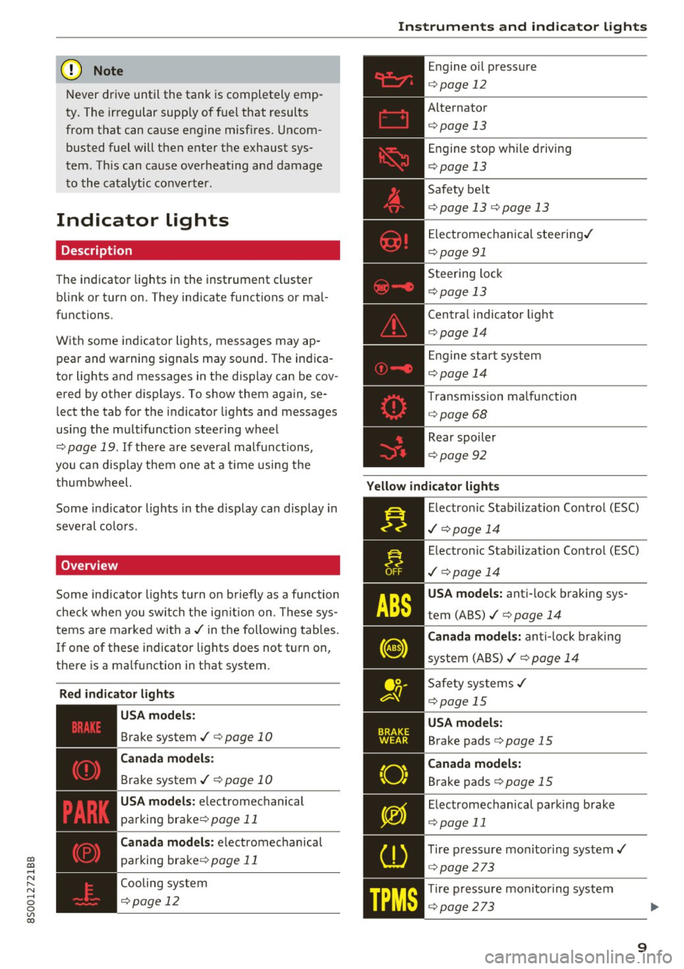
Some indicator lights turn on briefly as a function
check whe n you switch the ign ition on . These sys
tems are marked with a
,I in the following tables.
If one of these indicator lights does not turn on,
there is a ma lfunction in that system.
Red indicator lights
---------------
US A models :
Brake system ./ c;, page 10
Canada models:
Brake system ./ c;, page 10
USA models : electromechanical
parking brake¢
page 11
Canada models: electromechanical
parking brake¢
page 11
Cooling system
<=>page 12
Instruments and indicator lights
Engine oil pressure
c;,page 12
Alternator
¢ page 13
Engine stop while driving
¢page 13
Safety be lt
c;, page 13 c;, page 13
Electromechanical steering./
c;,page 91
Steering lock
¢page 13
Central indicator light
c;,page 14
Engine start system
c;,page 14
Transmission malfunction
c;, page 68
Rear spoiler
c;,page 92
Yellow indicator lights
Electronic Stabilization Contro l (ESC)
,I c;, page 14
Electronic Stabilization Control (ESC)
./ c;, page 14
USA models: anti-lock braking sys
tem (ABS)./
c;, page 14
Canada models: anti-lock braking
system (ABS) ./
c;, page 14
Safety systems ,I
c;,page 15
USA models:
Brake pads c;, page 15
Canada models:
Brake pads c;, page 15
Electromechanical parking brake
c;,page 11
Tire pressure monitoring system../
<=>page 273
Tire pressure monitoring system
<=>page 273
9
Page 17 of 322
co
co
.... N
" N .... 0
0
Vl c:o
nearest authorized Audi dealer or authorized
Audi Service Facility and have the malfunction
corrected.
@ Tips
For additional information on ESC and ABS,
see
~ page 88.
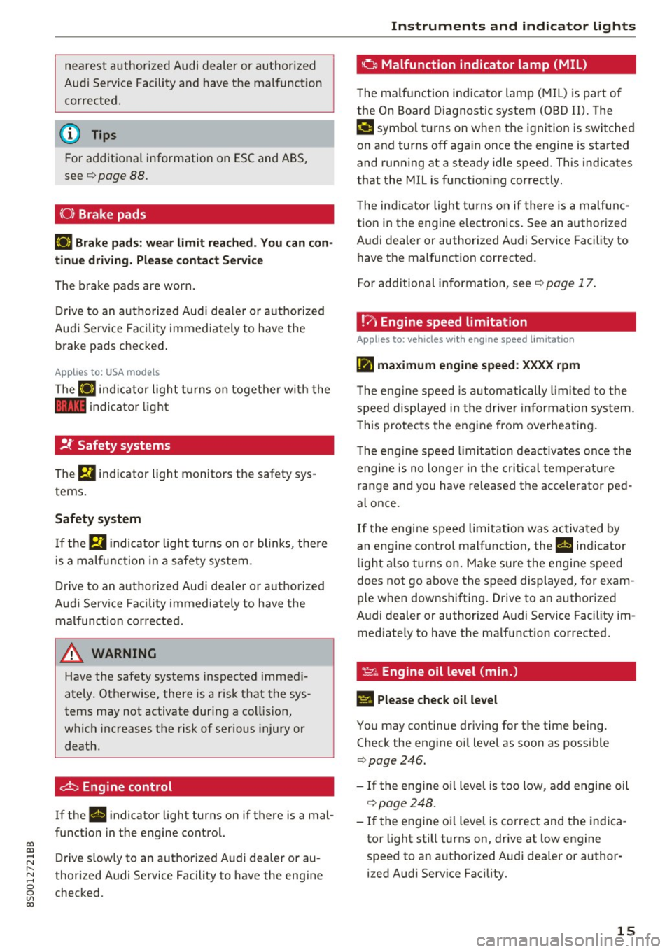
(0) Brake pads
EiJ Brake pads: wear limit reached. You can con
tinue driving. Please contact Service
The brake pads are worn.
Drive to an authorized Audi dealer or authorized
Audi Service Facility immediately to have the
brake pads checked.
Applies to: USA models
The EiJ indicator light turns on together with the
11111 indicator light
.!f Safety systems
The El indicator light monitors the safety sys
tems.
Safety system
If them indicator light turns on or blinks, there
is a malfunction in a safety system .
Drive to an authorized Audi dealer or authorized
Audi Service Facility immediately to have the
malfunction corrected.
_& WARNING
Have the safety systems inspected immedi
ately. Otherwise, there is a risk that the sys
tems may not activate during a collision,
which increases the risk of serious injury or death.
c±:, Engine control
-
If the II indicator light turns on if there is a mal
function in the engine control.
Drive slowly to an authorized Audi dealer or au
thorized Audi Service Facility to have the engine
checked.
Instruments and indicator lights
o Malfunction indicator lamp (MIL)
The malfunction indicator lamp (MIL) is part of
the On Board Diagnostic system (OBD II). The
¢'4 c;ymbol turns on when the ignition is switched
on and turns off again once the engine is started
and running at a steady idle speed. This indicates
that the MIL is functioning correctly.
The indicator light turns on if there is a malfunc
tion in the engine electronics. See an authorized
Audi dealer or authorized Audi Service Facility to have the malfunction corrected .
For additional information, see
c::> page 17.
!?i Engine speed lim itation
Applies to: vehicles with engine speed limitation
(II maximum engine speed: XXXX rpm
The engine speed is automatically limited to the
speed displayed in the driver information system.
This protects the engine from overheating .
The engine speed limitation deactivates once the
engine is no longer in the critical temperature
range and you have released the accelerator ped
al once.
If the engine speed limitation was activated by
an engine control malfunction, the
II indicator
light also turns on. Make sure the engine speed
does not go above the speed displayed, for exam
ple when downshifting. Drive to an authorized
Audi dealer or authorized Audi Service Facility im
mediately to have the malfunction corrected.
~ .. Engine oil level (min. )
II Please check oil level
You may continue driving for the time being.
Check the engine oil level as soon as possible
c::> page246.
-If the engine oil level is too low, add engine oil
~page 248.
- If the engine oil level is correct and the indica
tor light still turns on, drive at low engine
speed to an authorized Audi dealer or author
ized Audi Service Facility .
15
Page 20 of 322
Instrumen ts and ind icator ligh ts
On-Board Diagnostics
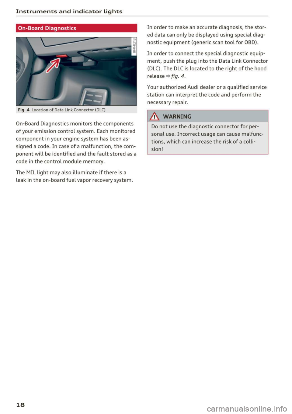
F ig. 4 Loc ation of D ata Link Connector (OLC)
On-Board Diagnostics monitors the components
of your emission control system. Eac h monitored
component in your engine system has been as
signed a code . In case of a ma lfunction, the com
ponent w ill be identified and the fa ult stored as a
code in the control module memory.
The MIL light may also ill uminate if there is a
leak in the on-board fuel vapor recovery system .
18
In order to make an accurate diagnosis, the stor
ed data can only b e display ed using special diag
nostic equipment (gener ic scan tool for OBD) .
In order to connect the special d iagnost ic equip
ment, push the plug into the Data Link Connector
(DLC). The DLC is located to the right of the hood
release
~ fig. 4.
Your a utho rized Aud i dea ler or a qua lified service
station can interpret the code and perform the
necessary repair.
A WARNING
Do not use t he diagnostic connector for per
sonal use. Incorrect usage can cause malfunc
tions, which can increase the risk of a co lli
sion!
-
Page 21 of 322
CD
CD
.... N
" N .... 0
0
Ill co
Driver information system
Overview
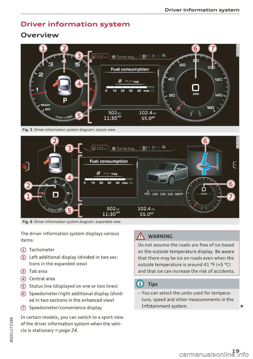
Fig. S Dr iver information system diagram: classic v iew
Fig. 6 D river information system diagram : expanded view
The driver information system displays various
items:
@ Tachometer
@ Left additional display (divided in two sec-
tions in the expanded view)
@ Tab area
@ Central area
® Status line (displayed on one or two lines)
@ Speedometer/right additional display (divid-
ed in two sections in the enhanced view)
(J) Speedometer/convenience display
In certain models , you can sw itch to a sport view
of the driver information system when the vehi
cle is stationary
¢ page 24 .
Driver in forma tion system
A WARNING
-Do not assume the roads are free of ice based
on the outside temperature display . Be aware
that there may be ice on roads even when the
outside temperature is around 41 °F (+5 °C)
and that ice can increase the risk of accidents.
(D Tips
-You can select the units used for tempera
ture, speed and other measurements in the
Infotainment system. .,,.
19
Page 22 of 322

Drive r inf orm ati on sy stem
- If your vehicle is stationary or if you are driv
ing at very low speeds, the temperature dis
played may be s light ly higher than the ac
tual temperature outside due to the heat
radiating from the engine.
- At temperatures below 41 °F (+S
0
(), a
snowflake symbol appears in front of the
temperature display¢,&.
Multifunction steering
wheel plus
Operating
A pp les to: ve hicles w ith multifunctio n steering wheel p lus
The Multifunction steering wheel plus* hos 14
buttons. You con use them to operate the driver
information system and the MMI functions ,
change the volume and switch the voice recogni
tion system* on and off.
Fig . 7 Infotainment system display
Fig . 8 Mult ifunc tion steering whee l, left side
Req uirement: the ignition must be switched on.
The driver information system contains mult iple
tabs
(D that display various informat ion @.
The follow ing tabs are available, depending on
veh icle equipment :
20
First tab Vehicle
Second Warnings
tab
a)
Third tab Radio c::> page 150
Media c::>page 155
Fourth tab Telephone*¢ page 114
Fifth tab Navigation
* c::> page 135
Map* c::> page 143
Sixth tab b) Sound¢ page 17 4
Audi connect*¢ page 126
Settings c::> page 174
a) This tab is only visible if at le ast one indicat or light or
message is shown or
if t h e correspond ing system is
switched on.
b) The contents of the tab de pend on the menu that was
used last.
@ Button ~
-Swit ch ing tab s: p ress the l<1 1>I bu tto n to the
left/right (for example, radio).
@ !VIEWI button
S witching th e view : press the !VIEWI button to
switch from the classic v iew
c::> page 19, fig. 5 to
the e nhanced view
c::>page 19, fig. 6.
@button ~
Returning to funct ions at higher levels
@ 121 and 19 contr ol butt ons
Opening/closing the selection menu or options
menu
c::> page 21.
(J) Left thumbwheel
-Sele cting a function in a m enu /list : turn the
left thumbwheel to the des ired function in a
menu or list (such as se lecting a station, Lap
times*) .
-Co nfirming a selection : press the left thumb
wheel (for example, confirm the station).
-Zoomin g in /out on th e map : when a map is
disp layed, turn the le ft thumbwheel up/down
to zoom in/o ut on the map.
Page 25 of 322
CD
CD
.... N
" N .... 0
0
Ill co
Tachometer
The tachometer displays the engine speed in rev
olutions per minute (RPM) .
The beginning of the red zone in the tachometer
indicates the maximum permissible engine speed
for all gears once the engine has been broken in
and when it is warm. Before reaching the red
zone, you should shift into the next higher gear,
choose the Dor S selector lever position, or re
move your foot from the accelerator pedal.
@ Note
The needle in the tachometer may only be in
the red area of the gauge for a short per iod of
time or there is a risk of damaging the engine .
The location where the red zone begins varies
depending on the engine.
@) For the sake of the environment
Upshifting early helps you to save fuel and re
duce operating noise.
Odometer
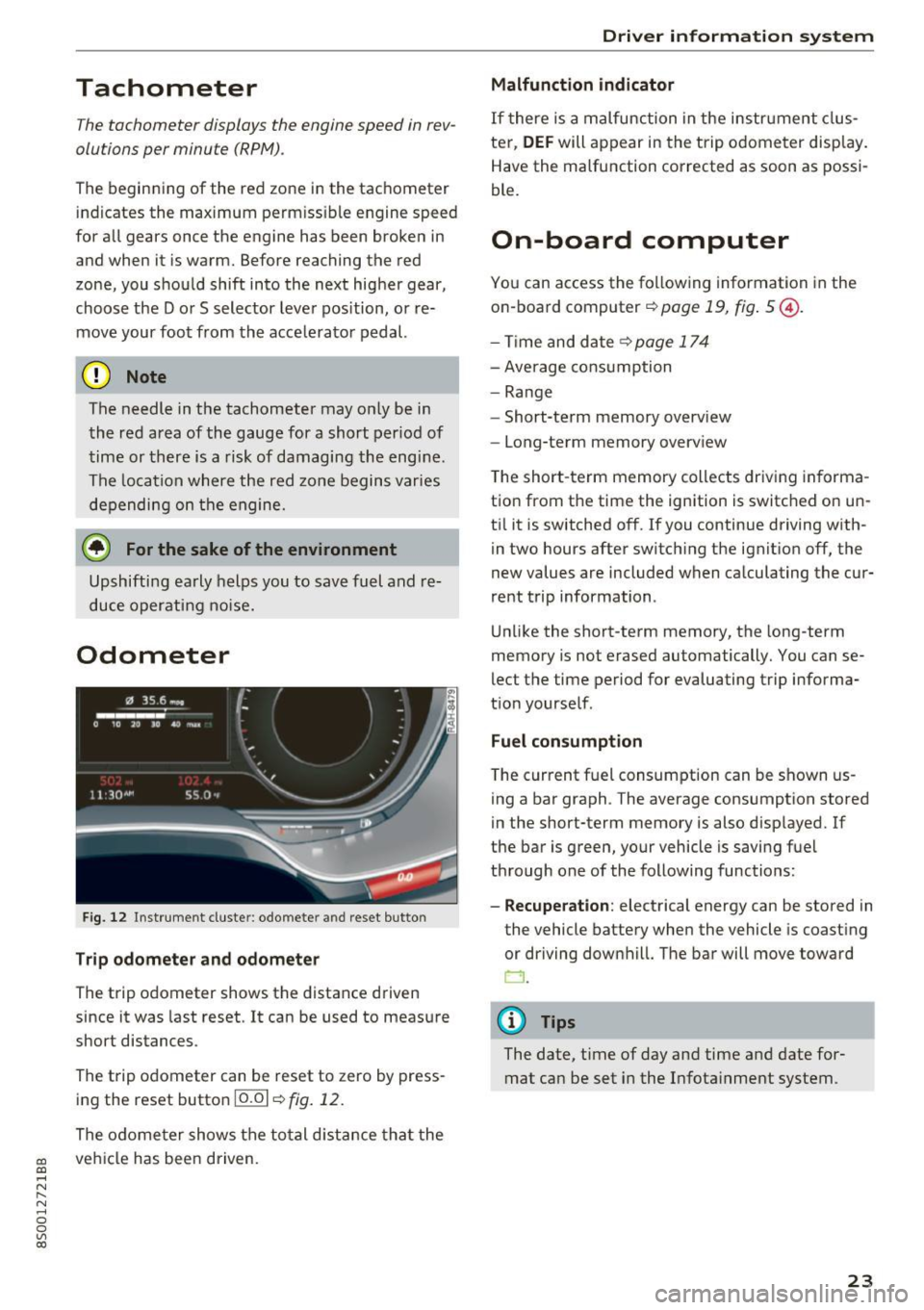
Fig. 12 Instrument cluste r: odomete r and reset button
Trip odometer and odometer
The trip odometer shows the distance driven
since it was last reset . It can be used to measure
short distances .
The trip odometer can be reset to zero by press ing the reset button 10.01
r=> fig. 12.
The odometer shows the total d istance that the
veh icle has been driven.
Driver in forma tion system
Malfunction indicator
If there is a malfunction in the instrument clus
ter,
DEF will appear in the trip odometer disp lay.
Have the malfunction corrected as soon as possi
ble.
On-board computer
You can access the following information in the
on-board computer
r=> page 19, fig . 5 @ .
-Time and date ~page 174
-Average consumption
-Range
- Short-term memory overv iew
- Long-term memory overview
The short -term memory collects driving informa
tion from the time the ignition is switched on un
til it is switched off. If you continue driving with·
in two hours after switching the ignition off, the
new values are included when calculating the cur
rent trip information .
Unlike the short-term memory, the long-term
memory is not erased automatically. You can se
lect the time period for evaluating trip informa
tion yourself .
Fuel consumption
The current fuel consumption can be shown us
ing a bar graph . The average consumption stored
in the short-term memory is also displayed. If
the bar is green, your vehicle is saving fuel
through one of the following functions:
- Recuperation : electrical energy can be stored in
the vehicle battery when the vehicle is coasting or driving downhill. The bar will move toward
CJ .
(D Tips
The date, time of day and time and date for
mat can be set in the Infotainment system.
23
Page 26 of 322
Driver information system
Sport view
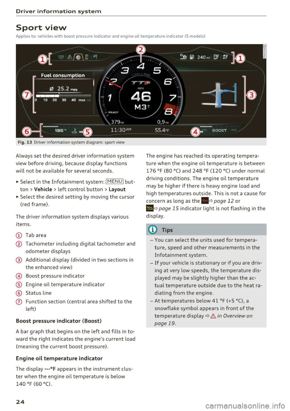
Applies to: ve hicles w ith boost p ressure indicato r and engine o il tempera ture indica tor (S models)
Fig. 13 Drive r informatio n system d iag ram: sport v iew
Always set the desired driver information system
view before driving, because display functions
will not be available for several seconds.
• Select in the Infotainment system:
IMENU I but
ton
> Vehicle > left contro l button > Layout
• Se lect the des ired sett ing by mov ing the cursor
(red frame).
The driver information system displays various
items.
(D Tab area
@ Tachometer including d igital tachometer and
odometer displays
@ Additional display (divided in two sections in
the enhanced view)
© Boost pressure indicator
® Engine oil temperature ind icator
@ Status line
(f) Funct ion sect ion (centra l area shifted to the
l eft)
Boost pressure indicator (Boost)
A bar graph that begins on the left and fills in to
ward the right indicates the engine's curre nt load
(meaning the current boost pressure).
Engine oil temperature indicator
The display ---°F appears in the instrument clus
ter when the engine oil temperature is below
140 °F (60 °().
24
The eng ine has reached its operating tempera
ture when the engi ne oil temperatu re is between
176 °F (80 °() and 248 °F (120 °C) under normal
driv ing cond itions. The eng ine o il temperature
may be higher if there is heavy engine load and
high temperatures outside. This is not a cause for
concern as long as the
. c> page 12 or
Ill e> page 15 indicator light is not flashing in the
display .
@ Tips
-You can select the units used for tempera
ture, speed and other measurements in the
Infota inment system.
- If your vehicle is stationary or if you are driv
ing at very low speeds, the temperature dis
played may be slightly higher than the ac
tual temperature outside due to the heat ra
diating from the engine.
- At temperatures below41 °F (+5 °(), a
snowflake symbol appears in front of the
tempe rature disp lay
c> .& in Overview on
page 19.