radio AUDI TT ROADSTER 2014 Owners Manual
[x] Cancel search | Manufacturer: AUDI, Model Year: 2014, Model line: TT ROADSTER, Model: AUDI TT ROADSTER 2014Pages: 244, PDF Size: 60.87 MB
Page 18 of 244
16 Instruments and warning/indicator lights
If the I (USA models) JII (Canada models)
indicator light does not go out, or if it illumi
nates wh ile you are driv ing, or if it starts to
blink, then there is a ma lfunction somewhere
in the system . If the light does not illuminate
when you switch on the ignition, this also
means there is a malfunction .
A WARNING
If you have a malfunction in the safety sys
tems, contact your authorized Audi dealer
immediate ly. Otherwise the safety sys
tems may not wo rk properly in an acci
dent.
4 Safety belt warning light
Applies to vehicles: with safety belt warning light
The warning light is a reminder to fasten
safety belts.
The warning light . comes on for a few sec
onds after the ignit ion is switched on as a re
m inder to fasten your safety belt.
Addit ional information on safety belts
Q page 101.
0 Battery
This warning/indicator light detects a mal
function in the generator or in the vehicle's
electrical system.
The. warning/ind icator light illuminates
when you sw itch on the ignit ion a nd must go
out after the engine has started.
• Alternator fault: Battery is not being
charged
If the indicator light turns on and the mes
sage appears, there is a ma lfunction in the
generator or vehicle electr ical system.
Drive to your authorized Audi dealer or quali
fied workshop immediately . Because the vehi
cle battery is discharging, turn off all unnec
essary electrical equipment such as the radio.
Seek professional ass istance if the battery
charge level is too low.
(•) Low battery: battery will be charged
while driving
If the indicator l ight turns on and the mes
sage appears, there may be limited starting
ability.
If this message turns off after a litt le while,
the battery charged enough while driving.
If the message does not turn off, have your
authorized Aud i dealer or qualified workshop
correct the malfunction.
requires immediate service or repair.
If the . symbol appears in the disp lay and
flashes, the oil pressure is too low. In add ition
to the symbol, the following message also ap
pears in the display:
Switch off engine! Oil pressure is too low
.,. Pull off the road and stop the vehicle.
• Shut the eng ine down.
.,. Check the engine oil level¢ page 170.
.,. Contact your authorized Aud i dealer for as-
sistance if necessary.
Engine oil level too low
If the engine oil leve l is too low, top off oil to
the proper level¢
page 170.
Engine oil level OK
If the . symbo l starts flashing again even
though the engine oi l level checks OK on the
dipstick,
do not start driving again and do
not let the engine run at idle.
Instead, con
tact your authori zed Aud i dealer for ass is
tance.
(D Tips
- The engine oil pressure symbol. is
not an indicator for a low engine oil lev
el. Do not rely on it. Instead, check the
oil level in your engine at regular inter
vals, preferably each time you refuel,
and always before going on a long trip.
Page 24 of 244
22 Driver in formation sy ste m
Driver information
system
Introduction
The Driver information display inside the in
strument cluster provides you, the driver ,
with important information.
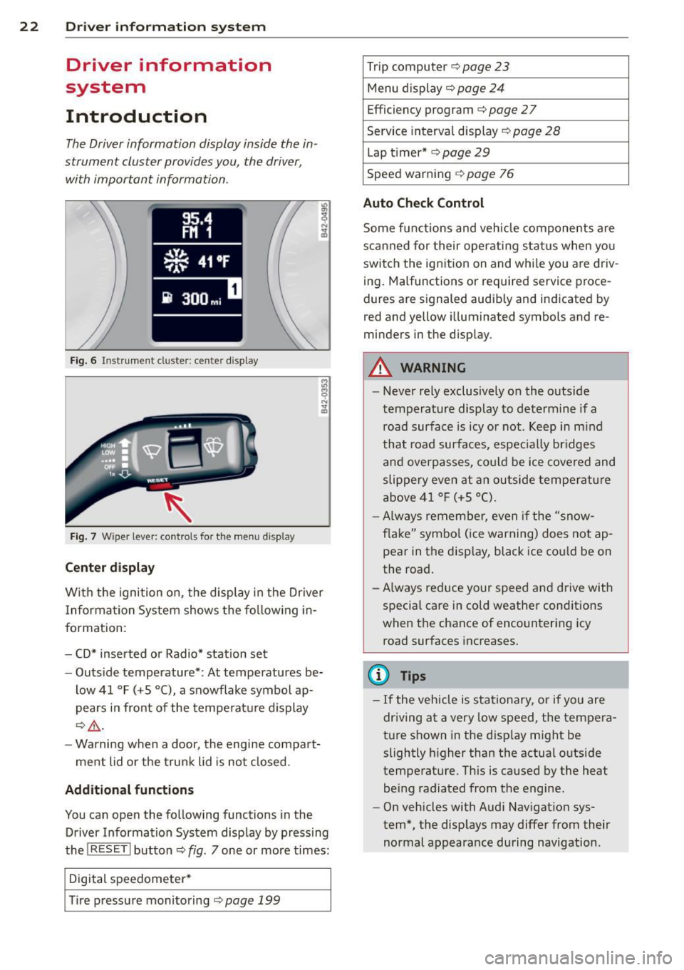
Fig . 6 In strum en t cl ust er: center display
Fig. 7 Wiper le ver: con trols fo r the menu disp lay
Cent er d ispla y
With the igni tion on, the display in the Dr iver
I nformation System shows the fol low ing in
formation :
- CD* inserted or Radio* station set
- Outs ide temperature* : At temperatures be-
low 41 °F ( +S °C), a snowflake symbol ap
pears in front of the temperatu re d isplay
c::> .&_ .
- Warning when a door, the engine compa rt-
ment lid or the trunk lid is not closed .
Additional functions
You can open the following functions in the
Driver Information Sys tem disp lay by p ressing
the
! R ESE T I button c::> fig. 7 one or more times:
Digital speedometer *
T ire pressure monitoring
c::> page 199
Trip computer c::> page 23
Menu d isplay c::> page 24
Efficiency program c::> page 27
Service interval disp lay
c::> page 28
Lap timer* c::> page 29
Speed warn ing
c::> page 76
Auto Check Control
Some f unct ions and vehicle components are
scanned for their operati ng sta tus when yo u
switch the ign ition on and whi le you a re driv
ing. Malfunctions or req uired service proce
dures ar e signaled audib ly and indicated by
red and yellow i lluminated symbols and re
m inders in the display.
A WARNING -
- Never rely exclusively on the outside
temperature display to determine if a
road surface is icy or not . K eep in m ind
that road surfaces, espec ially br idges
and overp asses, co uld be ice covered and
slippe ry even at an outside tempe ra tu re
above 4 1 °F (+5 °C).
- Always remembe r, even if the "snow
f lake" symbo l (ice warning) does not ap
pear in the disp lay, black ice could be on
the road .
- A lways reduce your speed and d rive with
specia l care in cold weather cond itions
when the chance of encountering icy
road surfaces increases.
(D Tips
- If the vehicle is stationary, or if you are
dr iving at a very low speed, the tempera
t u re s hown in the d isp lay m ight be
slightly h igher than the actual o utside
temperature. Th is is caused by the heat
being radiated from the engine .
- On vehicles with Audi Nav igat ion sys
tem *, the displays may differ from their
normal appearance during navigation .
Page 35 of 244
Master key with remote control
The remote control allows you to lock or un
lock the vehicle electronically .
The transmitter and battery are located in the
head of the remote control. The receiver is lo
cated inside the vehicle. The maximum effec
tive range depends on several things . Remem
ber, if the battery is wea k, the effective range
decreases.
If you need to replace the remote control, or if
you need to have it repaired, you must see
your author ized Audi dealer. Only then can
you use the key again.
(D Tips
- If the ignition is sw itched on, the remote
control system is deactivated .
- The remote control system can be affect ed by other systems operating in the
same frequency range close to the vehi
cle, such as mobi le telephones, televi
sion broadcasting stations, etc.
- Fo r De clarat ion of Compliance to United
Sta tes FCC and Indus try Canada regula
tions
¢ page 229.
Master key battery replacement
Each master key contains a battery housed
under the cover .
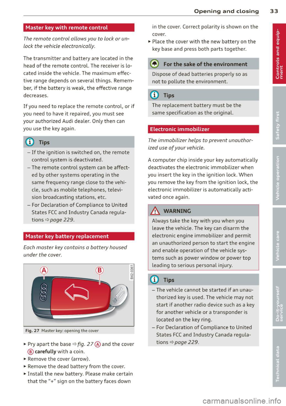
Fig . 27 Maste r key: open ing the cover
.. Pry apart the base¢ fig. 27@and the cover
@ care full y with a coin .
.,. Remove the cover (arrow) .
.,. Remove the dead battery from the cover .
.. Install the new battery . Please make certain
that the" +" sign on the batte ry faces down
Op enin g an d clos ing 33
in the cover . Correct polarity is shown on the
cover .
.. Place the cover with the new battery on the
key base and press both parts together .
@ For the sake of the env ironment
Dispose of dead batteries properly so as
not to pollute the environment.
(D Tips
The replacement battery must be the
same specification as the origina l.
Electronic immobilizer
The immobilizer helps to prevent unauthor
ized use of your vehicle.
A computer chip ins ide your key automatica lly
deactivates the electron ic immobilizer when
you insert the key in the ign ition lock. When
you remove the key from the ignition lock, the
electronic immobilizer is automatically acti
vated once again.
A WARNING
---
Always take the key with you when you leave the vehicle. The key can disarm the
electronic engine immobilizer and permit
an unauthorized person to start the engine
and enable operation of the vehicle sys
tems such as power w indow or power top
leading to serious persona l injury.
(D Tips
- T he ve hicle cannot be started if an unau
thorized key is used. The vehicle may not
start if another radio device s uch as a key
for another vehicle or a transponder is
located on the key ring .
- For Declaration of Compliance to United
States FCC and Industry Canada reg ula
tions¢
page 229 .
Page 38 of 244
36 Opening and clo sing
- The operation of the remote cont ro l key
can be temporarily disrupted by interfer
ence from transmitters in the vicin ity of
the vehicle work ing in the same frequen
cy range (e.g. a cell phone, radio equip ment) .
- In order to make sure the locking func
tion is working, you should always keep
your eye on the vehicle to make sure it is
properly locked .
- Do not use the remote control if you are
i nside the car, otherwise you may unin
tentionally lock the vehicle, and then you
would set off the anti-theft ala rm when
you try to start the engine or open a
door . In case this happens anyhow, push
the un lock button
CD .
- Use the panic function only if you are in
an emergency situation.
Resetting the remote control
The remote control must be reset if the vehi
cle does not unlock .
.,,. Press the unlock button CD on the remote
control.
.,,. Manua lly unlock the driver's door lock with
the mechanical key within 30 seconds.
.,,. Press either the lock- 1'.D or the unlock
CD but
ton to comp lete th e reset sequence .
Operating locks with the key
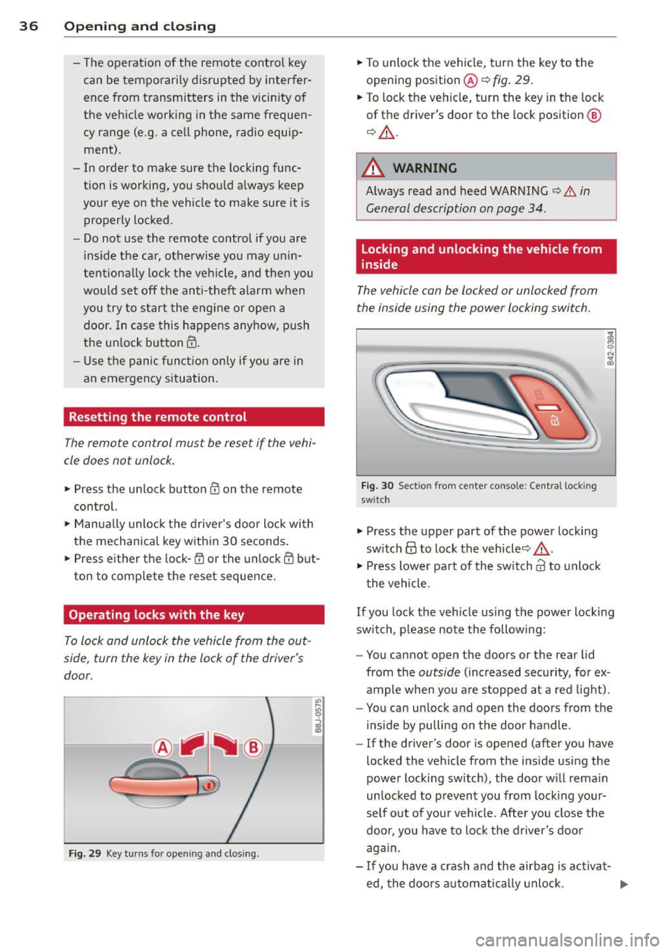
To lock and unlock the vehicle from the out
side , turn the key in the lock of the driver 's
door .
Fig. 29 Key tu rns fo r ope ning and clo sing.
.,,. To unlock the vehicle, turn the key to the
opening position@¢
fig. 29.
.,,. To lock the veh icle, turn the key in the lock
of the driver's door to the lock position
@
¢ &_ .
A WARNING
Always read and heed WARNING¢.&. in
General description on page 34 .
Locking and unlocking the vehicle from
inside
The vehicle can be locked or unlocked from
the inside using the power locking switch .
Fig. 30 Sec tion from center conso le: Ce ntra l locking
switch
.,,. Press the upper part of the power lock ing
sw itch
@ to lock the vehicle ¢&_ .
.,,. Press lower pa rt of the switch
crl to unlock
the vehicle .
If you lock the veh icle using the power locking
switch , please note the following:
- You cannot open the doors or the rear lid
from the
outside ( increased security, for ex
ample when you are stopped at a red light).
- You can unlock and open the doors from the
inside by pulling on the door handle .
-If the driver's door is opened (after you have
locked the vehicle from the inside using the
power locking switch), the door will remain
unlocked to prevent you from locking your
self out of you r vehicle. After you close the
door, you have to lock the driver 's door
aga in.
- If you have a crash and the airbag is activat-
ed, the doo rs automatically unlock. ..,.
Page 92 of 244
90 Homelink
Phase 1:
programming the overhead keypad
1. Make sure yo ur vehicle is wit hin o peratin g
range of the remote contro lled garage
door opener .
2. Set the parking brake¢.&. in General in
formation on page 89 .
3. Tur n the ignition on . Do not sta rt the e n
g ine!
4 . Pr ess and hold the two ou ts ide Home Link
b uttons
(D and @for app rox imately 2 0
seconds un til indicator light @¢fig . 98
begins to flash. Then release both but
tons . Do not hold the buttons for longe r
than
30 seconds.
.,. This procedure only needs to be performed
once . It erases the factory-set defau lt codes
and does not have to be repeated to pro
gram addit ional remote cont rols .
S . Press and hold the Hom elink button
(D ,
® or @ unt il the indica to r li gh t@
starts flashi ng
slowly. Re lease the bu tton.
.,. The system will remain in programming
mode for 5 minutes .
Co to the front of the
vehicle and proceed with phase 2 .
Phase 2:
programming the bumper mounted tran s
mitter
6 . Hold the original remote control at a dis
tance between
0 -6 in . (0 -15 cm) from the
b umper below the appropriate head light
fo r you r vehicle
q fig. 99 (u se the sho rtest
d istance possible).
7 . Aim t he remo te con trol jus t below the
driver side hea dligh t.
8 . Pr ess and hold the activation button on
the remote cont ro l.
.,. May be different in Canada. If so, press and
re-press (cycle) the activat ion b utton on your
remote control every two seconds.
9 . The eme rgency flashers will flash
three
time s
(after abo ut 15 -60 seconds) when
the programm ing is successf ul. Release
the butto n on the remote control.
.,. To program more devi ces, repea t steps 4 to
9.
10. Press and ho ld the trained Homelink but
ton and observe the indicator light @
¢fig. 98.
.,. If the ind icator lig ht is solid/contin uous,
prog ramm ing is comp lete and your device
should activate when you press and release
t he tra ined Homel ink b utton .
.,. If the ind icator light blinks rapidly fo r
2 se c
onds and is then a so lid/continuous ligh t,
procee d w ith p hase
3 to progr am a roll ing
code device.
Phase 3: rolling code programming
.,. A seco nd person o n a ladde r who can safely
reach th e garage door opene r moto r is rec
ommended .
11. Loc ate t he "lear n" bu tton on t he g arage
doo r opener motor ( re fer to the operating
inst ructions for the opener, as the loca
tion of t his button may vary by man ufac
turer).
12. Press and release the learn b utton on the
garage door opene r motor .
.,. Note : once the b utton is p ressed, the re a re
30 seconds in w hich to in it iate the next
step.
13. On t he Home link keypad ins ide t he ve hi
cl e, fi rmly press and hol d the Home link
bu tton prev ious ly progr ammed in phases
1 an d 2 for two seconds and release. Re
peat th is sequence
twice.
.,. Some vehicles may require the press/hold/
release sequence up to three times to com
plete the trai ning process .
.,. Homelink should now activate your rolling
code equipped d evice .
If the 5 minute time limit is exceeded , the
emergency flashers will flash one time to in
dicate that the p rocess has been te rm ina ted .
In this case, repeat steps 4 through 9.
If the emergency flashers do not flash
three
t imes (afte r about 15 -60 seconds) , program
ming was not successful. I n this case, repeat
steps 4 through 9 .
Remote contro l units for garage do or openers
in Canada are set to stop transmitting radio
fr eq uency sig nals afte r two seconds. Th is t ime ..,.
Page 93 of 244
may not be sufficient for the Homelink sys
tem to learn the radio frequency signal. Per
form all other steps as descr ibed above.
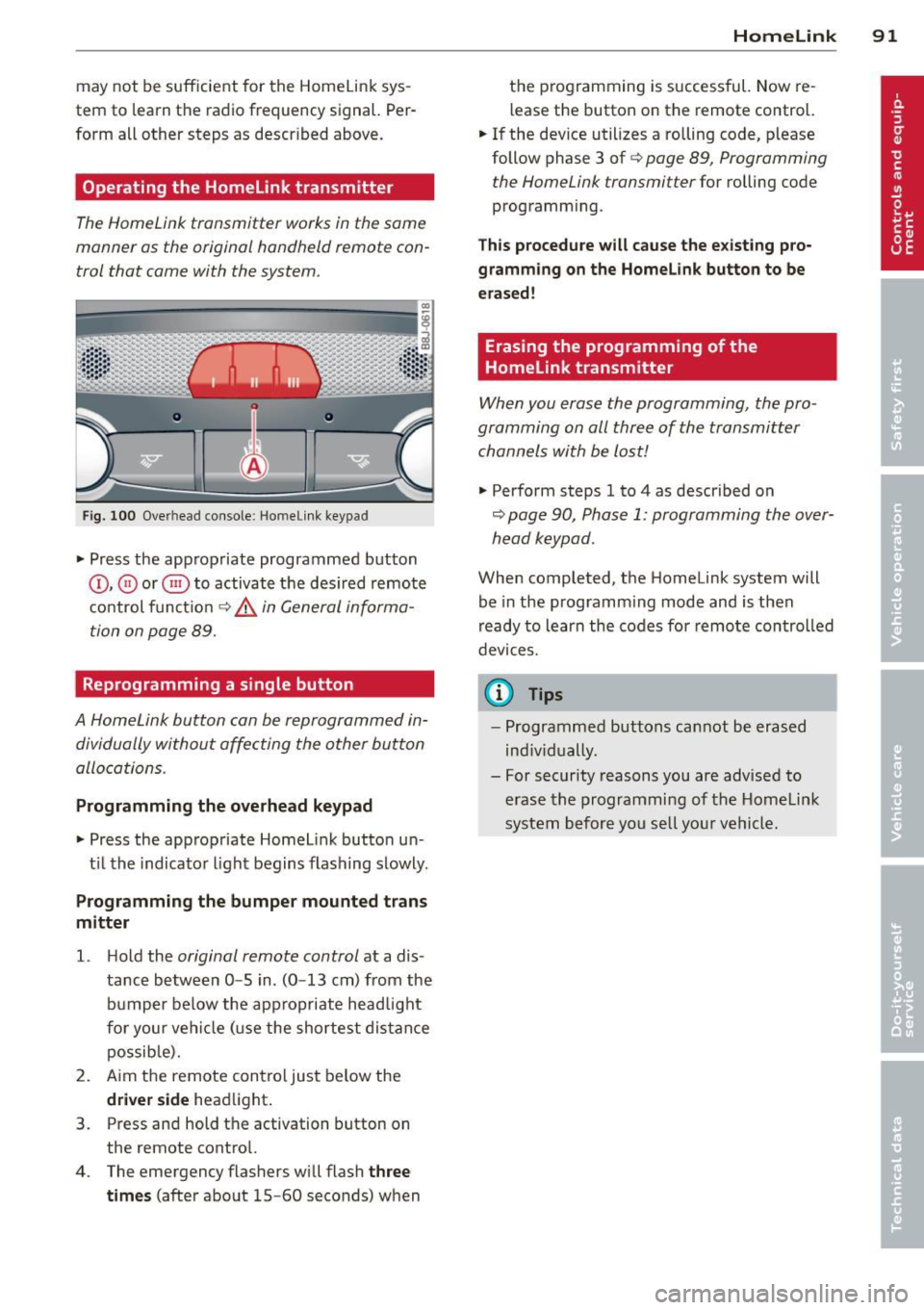
Operating the Homelink transmitter
The HomeLink transmitter works in the same
manner as the original hand held remote con
trol that came with the system.
Fi g. 100 Overhead co nsole: Homeli nk keypad
• Press the app ropriate programmed button
© , @ or@ to activat e th e des ired remote
c o ntrol func tion
¢ &. in General informa
tion on page 89.
Reprogramming a single button
A HomeLink button can be reprogrammed in
dividually without affecting the other button
allocations.
Programming the overhead keypad
• Press the app ropriate Homel ink button u n-
t il t he indicato r light begins flashing slowly .
Programming the bumper mounted tran s
mitter
1. H old the original remote control at a dis
tance between
0 -5 in . (0 -13 cm) from the
bumper below the appropriate headlight
fo r you r vehi cle (u se the sh ortest dis tan ce
possib le).
2. A im the remote con tro l just below the
driver side head light.
3. Press and hold the activation button on the remote contro l.
4 . The emergency flashers wi ll flash
three
times
(after about 15 -60 seconds) w hen
Homelink 91
the p rogramming is successful. Now re
l ease the button on the remote control.
• If the dev ice utilizes a rolling code, p lease
follow phase 3 of ¢
page 89, Programming
the Home Link transmitter
for rolling code
programm ing .
Th is p rocedu re will cause the e xisting pro
gramming on the Homelink button to be
erased!
Erasing the programming of the
Homelink transmitter
When you erase the programming, the pro
gramming on all three of the transmitter channels with be lost!
• Perform steps 1 to 4 as described on
~ page 90, Phase 1: programming the over
head k eypad .
When completed, the Homelink system will
be in the prog ramm ing mode and is then
r eady to learn the codes fo r remote controlled
devices.
(D Tips
- Programmed buttons can not be erased
ind iv idually.
- For security reasons you are advised to erase the programming of the Homelink
system before yo u se ll you r vehicle.
Page 124 of 244
122 Airbag sys te m
- If you must install a rearward facing
child safety seat on the front passenger
seat because of exceptional circumstan ces and the
PA SSEN GE R AIR BA G OFF
light does not appear and stay on have
the a irbag system inspected by your Audi
dealer.
- A tight tether or other strap on a rear
ward-fac ing child restra int attached to
the front passenger seat can put too much pressure on the weight-sens ing
mat in the seat and register more weight
than is actually on the seat. The heavier
weight registered can make the system
work as though an adu lt were on the seat
and deploy the Advanced Airbag when it
must be suppressed caus ing serious or
even fatal injury to the child.
- If, in exceptional circumstances, you
must install a forward-facing child re
straint on the front passenger seat, al
ways move the seat into its rearmost po sit ion in the seat's fo re and aft adjust
ment range, as far away from the airbag
as possib le . The backrest m ust be adjust
ed to an upright position. Make sure that
the
PASSENGER AIR BAG OFF light
comes on and stays on all the t ime when
ever the ignition is switched on.
A WARNING
- If the PASSENGER AIR BAG OFF light
does not go out when an adult is sitting
on the front passenger seat after taking
the steps described above, have the air bag system inspec ted by your Audi deal
er before transporting anyone on the
front passenger seat.
(D Tips
If the weight-sensing mat in the front pas
senger seat detects an empty seat, the
front airbag on the passenge r side will be
turned off, and
PASSENGER AIR BAG OFF
w ill stay on.
Repair, care and disposal of the airbags
Pa rts of the airbag system are i nstalled at
many diffe rent p laces o n your Aud i. Insta llin g,
removi ng, servicing or repa iring a part in an
area of the veh icle can damage a part of an
airbag system and prevent that system from
working properly in a coll is ion.
T he re a re some important t hings you have to
k now to make sure that the effectiveness o f
t h e system wi ll not be impaired and that dis
carded components do not cause injury or pol
l ute the environment.
A WARNING
Improper care, serv ic ing and repair proce
dures can increase the risk of personal in
j u ry and death by prevent ing an a irbag
from deploying when needed or dep loying
an a irbag unexpec tedly:
- Never cover, obst ruct, or change the
steer ing whee l horn pad or ai rbag cover
or the in st rument panel or mod ify them
in any way .
- Never attach any obje cts s uch as c up
holders or telephone mountings to the
sur faces covering the a irbag un its.
- For cle aning the horn pad or instr ument
panel, use only a soft, dry clo th or one
moistened with pla in water. Solvents o r
cleaners could damage the airbag cover
or change the st iffness or strength of the
material so that the airbag cannot de
p loy and protect properly.
- Never repair, adjust, or change any parts
of the a irbag system.
- All work on the steering wheel, instru
ment panel, front seats or e lectr ica l sys
tem (including the installation of audio
equ ipment, cellu lar telep hones and CB
radios, etc.) must be performed by a
qualified technic ian who has the training
and specia l equipment ne cessary.
- For any wo rk on the airbag system, we
strongly recommend that you see your
author ized Audi dealer or qualified work-
shop. ..,.
Page 150 of 244
148 Intelligent technology
Battery diagnosi s
Battery diagnosis continuously determines
the state of the battery. Sensors determine
battery voltage, battery current and battery
temperature. This determines the current
state of charge and the power of the battery.
Idling current management
I dling current management reduces energy
consumption while the vehicle is standing.
With the ignition switched off, it controls the
energy supply to the various electrical compo
nents. Data from battery diagnosis is consid
ered.
Depending on the battery's state of charge,
individual consumers are gradually turned off
to prevent excessive discharge of the battery
and thus maintain starting capability.
Dynamic energy management
While the vehicle is being driven, dynamic en
ergy management distributes the energy gen
erated according to the needs of the individu
al components. It regulates consumption, so
that more electrical energy is not being used
than is being generated and ensures an opti
mal state of charge for the battery .
(D Tips
-But even energy management cannot
negate the limits of physics. Consider
that the power and life of a battery are
limited .
- If starting ability is threatened, you are informed by a warning
~page 149,
Driver notification in the instrument
cluster display.
What you should know
The highest priority is given to maintaining
starting capability .
The battery is severely taxed in short -distance
driving, in city traffic and during the cold time
of year. Abundant electrical energy is re
quired, but only a little is generated.
It is also
critical if the engine is not running and electri- cal components are turned on.
In this in
stance energy is being consumed but none is
being generated.
It is in precisely these situations that you will
notice energy management actively regulat
ing the distribution of energy.
Vehicle stands for an extended period
If you do not drive your vehicle over a period
of several days or weeks , electrical compo
nents are gradually cut back or switched off .
This reduces energy consumption and main
tains starting capability over a longer period.
Take into consideration that when you unlock
your vehicle, some convenience functions ,
such as the remote key or power seat adjust
ment, may not be available. The convenience
functions will be available again when you
turn on the ignition and start the engine.
With the engine turned off
If you listen to the radio, for example, with
the engine turned off, the battery is being dis
charged.
If starting capability is jeopardized due to en
ergy consumption, a message appears in the
driver information display.
You have to start the engine to charge the
battery.
With the engine running
Although electrical energy is generated when
the vehicle is being driven, the battery can be
come discharged. This happens mostly when
little energy is being generated and a great
deal consumed and the battery's state of
charge is not optimal.
To bring the energy balance back into equili
brium, consumers which require especially
large amounts of energy are temporarily cut
back or switched off . Heating systems in par
ticular require a great deal of energy. If you
notice, for example, that the heated seats* or
the heated rear window are not heating, they
have been temporarily cut back or switched .,.
Page 181 of 244
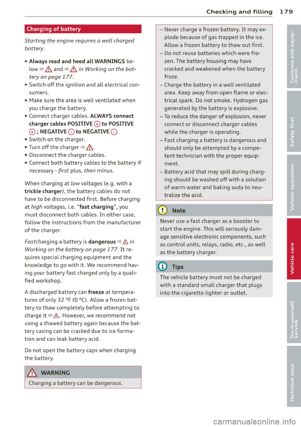
Charging of battery
Starting the engine requires a well charged battery.
11-Al way s read and heed all WARNING S be
low¢
A and ¢ A in Working on the bat
tery on page 177.
11-Switch off the ignit ion and all electrical con
sumers.
11-Make sure the area is well vent ilated when
you charge the bat tery.
11-Connect charger cables. ALWAY S co nnect
charge r cables POSITI VE
G) to POSITIVE
G) ; NEGATIVE Qto NEGA TIV E Q .
11-Switch on the charger.
11-Turn off the charger¢ &_.
11-Disconnect the charger cables.
11-Connect both battery cables to the battery if
necessary -
first plus, then m inus.
When charging at
low voltages (e.g. with a
trickle charg er), the battery cables do not
h ave to be d isconnected first. Before charging
at
high voltages, i.e. " fas t charging ", you
must disconnect both cables. In e ithe r case,
follow the instru ctions from the man ufactu rer
of the charger .
Fastcharging a battery is
dan gerou s¢ & in
Working on the battery on page 177.
It r e
q ui res specia l charg ing equipment and the
know ledge to go with it. We recommend hav
ing your battery fast charged on ly by a quali
f ied workshop .
A discharged battery can
freeze at tempera
tures of on ly 32 °F (0 °C). A llow a frozen bat
tery to thaw completely befo re attempting to
charge it¢ & . However, we recommend not
using a thawed battery again because the bat
tery cas ing can be cracked due to ice forma
tion and can leak battery acid.
Do not open the battery caps when charging
the battery.
A WARNING
-
Charging a battery can be dangerous.
Checkin g and fillin g 179
-Never charge a frozen battery. It may ex
plode because of gas trapped in the ice.
Allow a frozen battery to thaw out first.
- Do not reuse batteries wh ich were fro
zen. The battery housing may have
cracked and weakened when the battery
froze.
- Charge the battery in a well ventilated
area. Keep away from open flame or elec
trical spark. Do not smoke. Hydrogen gas
generated by the battery is explos ive.
- To reduce the danger of explosion, never
connect or d isconnect c harger cab les
while the charger is ope rat ing.
- Fast cha rging a batte ry is dangerous and
should only be attempted by a compe
tent techn ic ian with the prope r equip
men t.
- Battery acid that may spi ll dur ing cha rg
i n g should be washed off wi th a solu tion
of wa rm w ater and baking soda to neu
trali ze the ac id.
(D Note
Neve r use a fast cha rg er as a boost er to
star t the engi ne. This w ill ser iously dam
age sens it ive e lectronic componen ts, su ch
as cont ro l units, re lays, radio, etc., as well
as the batte ry charger.
(D Tips
T he vehicle ba tte ry mu st not be charged
wi th a standa rd small charger that plugs
into t he cigarette lighter or outlet . •
•
Page 217 of 244
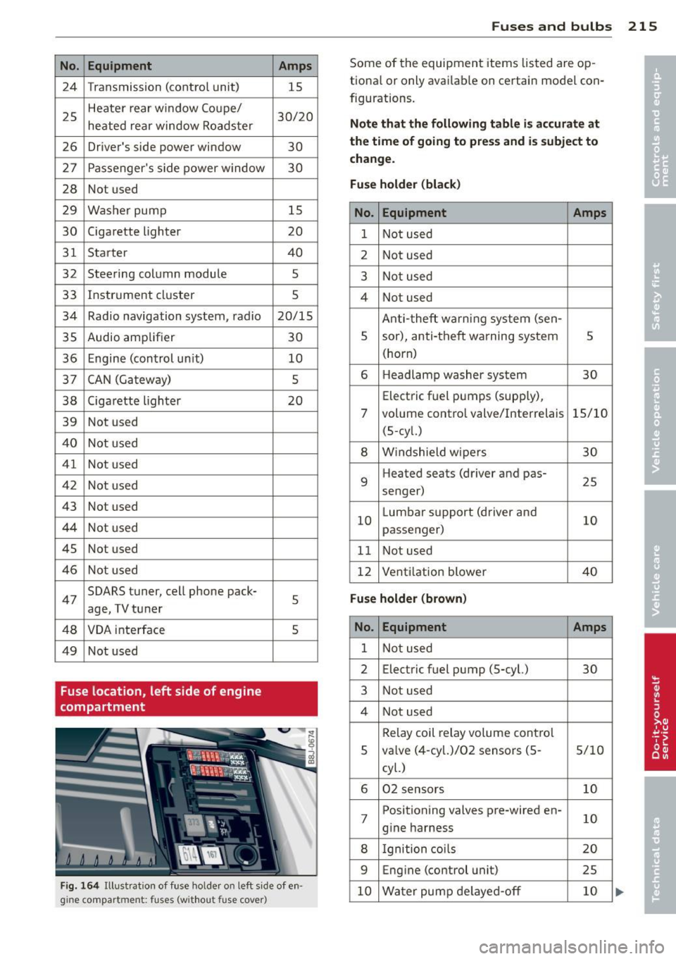
No. Equipment 24 Transmission (control unit)
25 Heater rear window Coupe/
heated rear window Roadster
26 Driver's side power window
27 Passenger's s ide power window
28 Not used
29 Washer pump
30 Cigarette lighter
31 Starter
32 Steering column module
33 Instrument cluster
34 Radio navigation system, radio
35 Audio amplifier
36 Engine (control un it)
37 CAN (Gateway)
38 Cigarette lighter
39 Not used
40 Not used
41 Not used
42 Not used
43 Not used
44 Not used
45 Not used
46 Not used
47 SOARS
tuner, cell phone pack-
age, TV tuner
48 VOA inte rface
49 Not used
Fuse location, left side of engine
compartment Amps
15
30/20
30
30
15
20
40
5
5
20/15
30 10
5
20
5
5
Fig. 164 Illustrat ion of fuse ho lder on left side of en
gine compart ment: fuses (without fuse cover)
Fuse s and bulb s 215
Some of the equipment items listed are op
tiona l or only avai lab le on certain model con
figurations.
Note th at the foll owing t abl e is ac cur ate at
the time of going t o pre ss and i s subject to
ch ang e.
Fus e holder (bla ck )
No. Equipment Amps
1 Not used
2 Not used
3 Not used
4 Not used
Anti-theft warning system (sen-
5 sor), anti-theft warning system
5
(horn)
6 H
eadlamp washer system
30
Electric f uel pumps (supp ly),
7 volume contro l valve/Interrelais 15/10
(5-cy l.)
8 W indshield w ipers 30
9 Heated
seats (driver and pas-
25
senger)
10 L
umbar support (driver and
10
passenger)
11 Not used
12 Vent
ilation blower
40
Fu se holder (brown )
No. Equipment Amps
1 Not used
2 Electric
fuel pump (5-cyl.)
30
3 Not used
4 Not used
Relay coil relay volume cont ro l
5 va
lve (4-cy l.)/02 sensors (5 -
5/10
cyl.)
6 02 sensors 10
7 Positioning valves pre-wired en-
10
g ine harness
8 Ignition coi ls 20
9 Eng
ine (control unit)
25
10 Water pump de layed-off 10