tow AUDI TT ROADSTER 2014 Owners Manual
[x] Cancel search | Manufacturer: AUDI, Model Year: 2014, Model line: TT ROADSTER, Model: AUDI TT ROADSTER 2014Pages: 244, PDF Size: 60.87 MB
Page 4 of 244
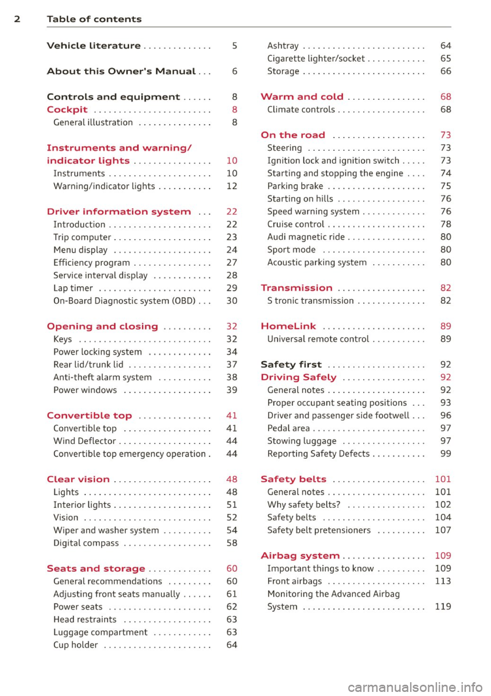
2 Table of contents Vehicle literature .. .. .. .. .. ... .
About this Owner's Manual ...
Controls and equipment .. ... .
Cockpit ................ .... .. . .
General illus tration .... ... .. .. ... .
Instruments and warning/
indicator lights ........ .. .. .. . .
Ins truments . .. .. ..... ... .. .. ... .
War ning/ indi cator lights ... .. ... .. .
Driver information system .. .
Introduct ion . .. .. ..... ... .. .. ... .
Trip computer .. .. ..... ... .. .. ... .
M enu display . ........... .... ... .
Efficiency program ........ .. .. .. . .
Service interval d isp lay ..... ... .. . .
Lap timer .. .......... ........ .. .
On- Board Diagnostic system (OBD) .. .
Opening and closing .. .. .. .. . .
Keys ........................ .. .
P owe r locking system ............ .
R ear lid/ trun k li d ................ .
Ant i- t heft ala rm system ... .. .. .. . .
P owe r win dows .. ..... ... .. .. ... .
Convertible top .............. .
Convertible top ....... ... .. .. ... .
W ind Deflector . .. ..... ... .. .. ... .
Conve rtible top eme rgency o peration .
Clear vision .. .. ..... ... .. .. ... .
Lights ...... .. .. ..... ... .. .. ... .
Inter ior lights .. . ...... ... .. .. ... .
V1s1on . .. ................. .. ... .
W iper and washer system .. .. .. ... .
D ig ita l compass ........... .... .. .
Seats and storage ....... .. .. . .
Ge neral recommendat ions ........ .
Ad just ing front seats manually .. ... .
P owe r seats ... .... ...... .. .. .. . .
5
6
8
8
8
1 0
1 0
12
2 2
2 2
23
24
27
28
29
30
32
32
34
37
3 8
39
4 1
41
44
4 4
4 8
48
5 1
52
54
58
60
60
61
62
H ead res traints . . . . . . . . . . . . . . . . . . 63
L uggage compartmen t . . . . . . . . . . . . 63
Cup holder . . . . . . . . . . . . . . . . . . . . . . 6 4 Asht
ray ... .... .. ... .. ..... .... . .
Cigarette lighter/socket . ..... ... .. .
Storage ... .. .. .. .. ... .. .. .. .. .. .
Warm and cold ... .. ..... .... . .
Climate controls .. .. .... .... ... .. . 6
4
65
66
68
68
On the road . . . . . . . . . . . . . . . . . . . 73
Stee ring . ..... .. ... .. ..... ... .. .
Ignition lock and ignition sw itch .. .. .
Starting and stopping the engine ... .
Parking brake ................... .
Starting on hills ....... .......... .
S peed warning system ............ .
Cru ise con trol ... . ... ... .... ... .. .
Audi mag netic ride ............... .
Spo rt mode . ................. .. .
Acoustic parking sys tem
Transmission ................. .
S troni c transmission . ... .... ... .. .
Homelink ... .. ... .......... .. .
U nivers al remote contro l ...... .. .. .
Safety first .. .. ... .......... .. .
Driving Safely .............. .. .
Genera l notes .... ... .. ..... ... .. .
Pro per occ upant seatin g positions . . .
Drive r and passenger side footwe ll .. .
Pedal area . .... .. ............. .. .
Stow ing luggage . ............. .. .
Repo rting Sa fety Defects .......... .
Safety belts .................. .
General notes ................... .
Why safety belts? ... .. ....... ... .
Safety belts ..... ............... .
Safety be lt pretensioners ......... .
73
73
74
75
76
76
78
8 0
80
8 0
82
8 2
89
89
92
92
92
93
96
97
97
99
101
101
102
10 4
107
Airbag system . . . . . . . . . . . . . . . . . 109
Important th ings to know . . . . . . . . . . 109
Fron t air bags . . . . . . . . . . . . . . . . . . . . 113
Moni to ring the Adv ance d Ai rbag
System . . . . . . . . . . . . . . . . . . . . . . . . .
119
Page 5 of 244
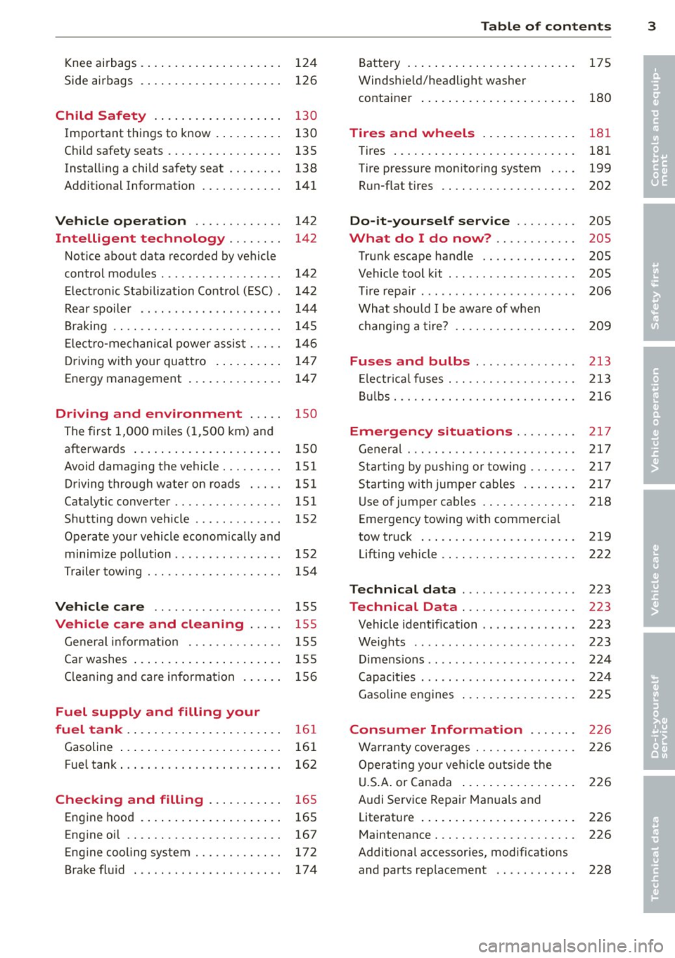
Knee airbags . . . . . . . . . . . . . . . . . . . . . 124
Side airbags . . . . . . . . . . . . . . . . . . . . . 126
Child Safety . . . . . . . . . . . . . . . . . . . 130
Important things to know ......... .
Child safety seats ................ .
Instal ling a chi ld safety seat .. .. .. . .
Additional Information ........... .
Vehicle operation ............ .
Intelligent technology .. .. .. . .
Notice about data recorded by vehicle
control modules .............. ... .
Electronic Stabilization Control (ESC) .
Rear spoiler ................ ... . .
Braking ........................ .
E lect ro-me chan ical power assis t ... . .
D riving w ith your quattro ......... .
Energy management ............. .
Driving and environment .....
The first 1,000 miles (1,500 km) and
afterwards .............. .. .. .. . .
Avoid damaging the vehicle ........ .
Driving through water on roads ... . .
Catalytic converter ............... .
Shutting down vehicle ............ .
Operate your vehicle economically and
minimize pollution ............... . 130
135
138
141
142
142
142
142
144
145
146
1 47
147
1 5 0
150
151
151 151
152
15 2
Tra iler towing . . . . . . . . . . . . . . . . . . . . 154
Vehicle care . . . . . . . . . . . . . . . . . . . 155
Vehicle care and cleaning . . . . . 155
General information . . . . . . . . . . . . . . 155
Car washes . . . . . . . . . . . . . . . . . . . . . . 155
Cleaning and care information . . . . . . 156
Fuel supply and filling your
fuel tank . . . . . . . . . . . . . . . . . . . . . . .
16 1
Gasoline . . . . . . . . . . . . . . . . . . . . . . . . 161
Fuel tank. . . . . . . . . . . . . . . . . . . . . . . . 162
Checking and filling . . . . . . . . . . . 16 5
Engine hood . . . . . . . . . . . . . . . . . . . . . 165
Eng ine oil . . . . . . . . . . . . . . . . . . . . . . . 167
Eng ine cooling system............. 172
Brake fluid ...................... 174
Table of contents 3
Battery . . . . . . . . . . . . . . . . . . . . . . . . . 175
Windshield/headlight washer
container . . . . . . . . . . . . . . . . . . . . . . . 180
Tires and wheels ........... .. .
Tires ..... .. .... .. . .. .......... .
Tire pressure monitoring system ... .
Run-flat tire s .. .. ............... .
Do-it-yourself service ........ .
What do I do now? ........... .
Trunk escape handle ............. .
Vehicle tool kit .... .............. .
T ire repai r .... ... .. ............. .
What should I be aware of when
h . t
' 7 c angmg a ire .................. .
Fuses and bulbs .. .. .. ..... ... .
El ectr ical fuses . .. .. ............. .
Bulbs .......................... .
Emergency situations ........ .
General ........................ .
Starting by pushing or towing ...... .
Starting with jumper cables ....... .
U se of jump er cables ............. .
Emergency towing with commercia l
tow truck ...................... .
Lifting vehicle .. .. ............... . 181
181
199
202
205
205
205
205
206
209
213
213
216
217
217
217
217
218
219
222
Technical data
. . . . . . . . . . . . . . . . . 223
Technical Data . . . . . . . . . . . . . . . . . 223
Vehicle identification . . . . . . . . . . . . . . 223
Weights . . . . . . . . . . . . . . . . . . . . . . . . 223
Dimensions . . . . . . . . . . . . . . . . . . . . . . 224
Capacities . . . . . . . . . . . . . . . . . . . . . . . 224
Gasoline engines . . . . . . . . . . . . . . . . . 225
Consumer Information . . . . . . . 226
Warranty coverages . . . . . . . . . . . . . . . 226
Operating your vehicle outside the
U.S. A. or Canada . . . . . . . . . . . . . . . . . 226
Audi Service Repair Manuals and
Literature . . . . . . . . . . . . . . . . . . . . . . . 226
Maintenance. . . . . . . . . . . . . . . . . . . . . 226
Additional accessories, modifications
and parts rep lacement . . . . . . . . . . . . 228
•
•
Page 19 of 244
Instrument s and warnin g/indic ator ligh ts 17
- The yello w oil level warning indic ation
II require s oil refill o r work shop se rv
i c e without del ay. Do not w ait until the
r ed o il p ressure warning symbol.
sta rts to flash befo re you respond to
th e l ow oil l eve l warning
I'll . By th en,
your engine ma y alr eady ha ve suff ere d
s eriou s damag e.
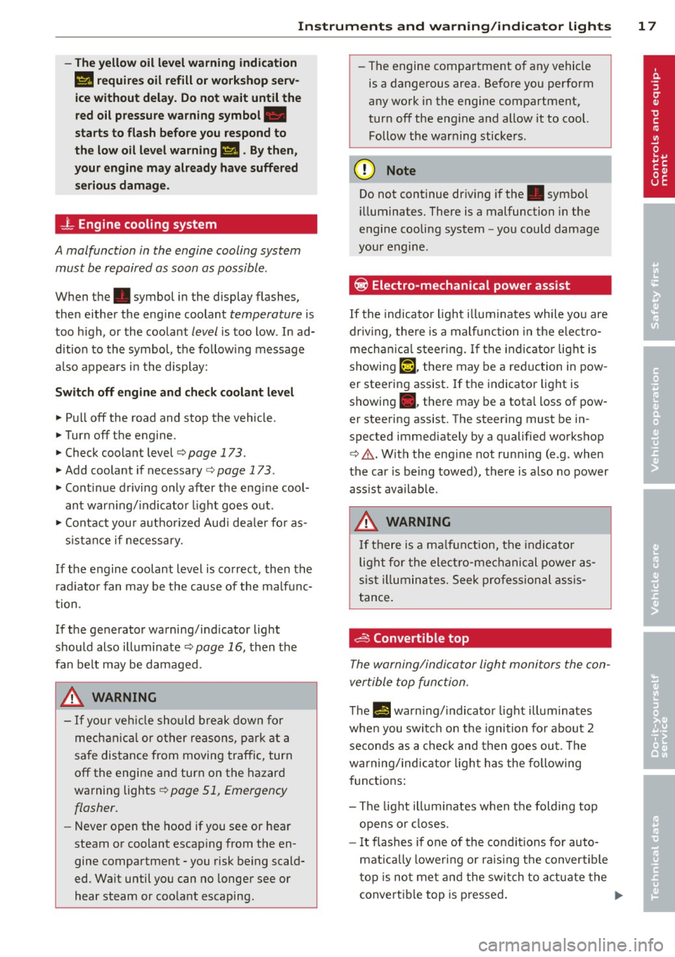
_L Engine cooling system
A malfunction in the engine cooling system
must be repaired as soon as possible .
When the. symbol in the display flashes,
then either the eng ine coolant
temperature is
too h igh, or the coolant
level is too low . In ad
d ition to the symbol, the fo llowing message
a lso appears in the display:
Sw it c h off engin e and ch eck coo lant l evel
~ Pull off the road and stop the vehicle.
~ Turnoff the engine.
~ Check coolant level ¢ page 173.
~ Add coolant if necessary ¢ page 173 .
~ Conti nue driving only after the eng ine cool
ant warn ing/ indicator light goes out .
~ Contact you r authorized Audi dea le r fo r as-
s istance if necessary .
If the engine coolant level is correct, then the
radiato r fan may be the cause of the malfunc
tion .
If the generator warning/ind icator light
should also illuminate ¢
page 16, then the
fan belt may be damaged .
A WARNING
-If your veh icle should break down for
mechanical or other reasons, park at a
sa fe distance from moving traffic, turn
off the engine and turn on the hazard
warning lights ¢
page 51, Emergency
flasher.
- Never open the hood if you see or hear
steam or coolant escaping from the en
gine compartment - you risk being scald
ed . Wait until you can no longer see or
hear steam or coolant escaping . -
The engine compartment of any vehicle
is a dangerous area . Before you perform
any work in the engine compartment,
turn off the eng ine and allow it to cool.
Follow the warn ing stickers .
(D Note
Do not continue dr iv ing if the . symbol
ill uminates. There is a malfunction in the
engine cooling system -you could damage
your engine .
~ Electro-mechanical power assist
If the indicato r light illum inates while you are
driv ing , there is a malfunction in the electro
mecha nica l steering. If the indi cator light is
showing
'".[-1. there may be a reduction in pow
er steering assist. If the indicator light is
showing ., ther e may be a tota l loss of pow
er steering assist. The stee ring must be in
spected immed iately by a qualified workshop
¢ .&. .With the eng ine not running (e.g . when
the car is being towed), there is also no power
ass ist available .
A WARNING
-
If there is a ma lfunction, the indicato r
l ight for the electro-mechanical power as
sist il l uminates. Seek pro fessional assis
tance.
~ Convertible top
The warning/indicator light monitors the con
vertible top function .
The !I warning/ indicator light illumi nates
when you switch on the ignition for about 2 seconds as a check and then goes out. The
warning/indicator ligh t has the following
functions :
- The light illumi nates when the foldi ng top
opens or closes.
- I t flashes if one of the cond it ions for auto
mat ically lower ing or ra is ing the convertible
top is no t met and the switch to actuate the
convertible top is pressed . .,..
Page 29 of 244
Boost pressure indicator (boost )
A bar graph that begins on the left and fills in
towa rd the right indicates the engine's cu r
rent load (meaning the c urrent boost pres
sure) .
Engine oil t emperature indicator
If the engine oil temperat ure is be low 140 °F
(60 °C), the
't:::7-symbo l followed by th ree hy
phens" -- -'' and the °C unit is shown .
The engine has reached its opera ting temper
ature when the e ngine o il temperat ure is be
tween
176 °F (80 °() and 248 °F (1 20 °() un
der normal driving conditions. The engine oil
temperature may be higher if there is heavy
engine load and high temperatures outside.
This is not a cause for concern as long as the
• ¢ page 16 or 1\1 ¢ page 20 warning light
i n the display does not flash .
Efficiency program
Description
Applies to vehicles: with trip computer with efficiency
program
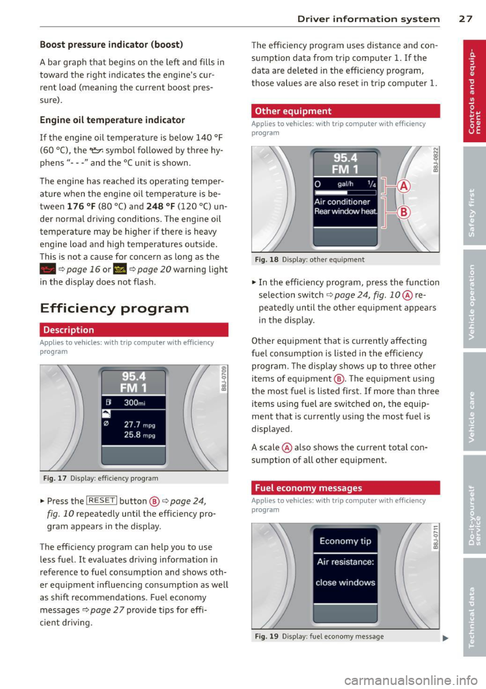
F ig. 17 Display : effic iency program
• Press the I RESE T I button @¢ page 24,
fig. 10 repeatedly until the efficiency pro
gram appears in the display.
The eff iciency program can help you to use
less fuel. It evaluates driving information in
reference to fuel consumption and shows oth
er equipment influenc ing co nsumption as well
as shift recommendations . Fuel economy
messages ¢
page 2 7 provide tips for effi
cient dr iv ing .
Dr iver in formation system 2 7
The efficiency program uses distance and con
sumption data from trip computer
1. If the
data are deleted in the efficiency program,
those values are also reset in tr ip computer
l.
Other equipment
Appl ies to vehicles: with trip computer with efficiency
prog ram
Fi g. 18 D isplay: other equ ipment
• In the efficiency program , press the function
selectio n switch
¢ page 24, fig. 1 0 @ re
peated ly until the other equipment appea rs
in the display.
Other equipment that is currently affecti ng
fuel consump tion is listed in the effi cien cy
program. The display shows up to th ree other
items of equ ipment @. The equ ipment using
the most fuel is listed first. If more than three items using fuel are switched on, the equip
ment that is currently us ing the most fuel is
displayed .
A scale @also shows the current tota l con
sumption of all other equipment .
Fuel economy messages
Applies to vehicles: with trip computer with efficiency
program
Fig . 1 9 D isplay: fue l economy message
Page 43 of 244
Convertible top
Convertible top
General information
The comprehensively engin eered design of the
f abric convertib le top a llows it to be operated
qu ickly and simply. When open, the convert i
b le top is stowed completely in a tonneau pro
vided spec ifically for this purpose.
I n normal operating conditions, the converti
b le top is wind -and waterp roof. Under certa in
circumstances, a small quantity o f droplets
might form, but on ly in extremely inclement
weather, e.g . torrentia l or contin uous heavy
rain. This is normal and not a cause for con
cern.
F ollow the care instructions
Q page 155 to
maintain the convertible top's attractive ap
pearance and to keep it wind- and waterproof.
Please follow these instructions as well:
- Stow and open the convertib le top only
when it is clean. When the top is folded
away, sharp-edged contaminants can build
up as silt and cause wear spots o n the rear
window, which may damage the convertible
top over time. Of course, ice and snow should also be removed before open ing the
convertible top.
- Under no c ircumstances should you use
sharp-edged or abrasive objects to remove
ice and snow . Use a commerc ial ice scraper
to remove ice from o f the rear window.
- T he convert ible top should be opened only if
it is complete ly d ry. If the convertib le top is
opened and then stored wet, unattractive
indentations may develop . In addition, over
time, mold and mildew stains can develop.
- Do no t leave the convertible top open for
several weeks at a time; instead, open and
close it from time to time so that the fabric
does not disco lor where it folds, and to pre
vent creases from forming. This is espec ially
important if it happens to be stowed wh ile
still damp on occasion.
- Because the fabric becomes less flexible
when temperatures drops below zero, we
Convertible top 41
recommend not operating the convertible
top below O°C.
A WARNING -
- When operat ing the convertible top,
make sure that any external factors (e.g.
the wind) do not impair its funct ion or
e ndanger other drivers.
- Never drive wh ile the convertib le top is
not properly secured. Otherwise , it may
be pulled open by the wind. This can
cause injur ies and damage to the vehicle
- danger of an accident!
- When opening and closing the converti-
ble top make sure to keep yourself and
o thers clear of a ll movi ng pa rts. Risk of
in jur y!
d) Note
-Always make su re that there is enough
clearance above the veh icle so that the
c onvertib le top is not damaged when
opening and clos ing.
- Do not place any objects in the tonneau
t o avoid damage when open ing the con
ver tible top.
(D Tips
- Th e convert ible top should be operated
only wi th the ign ition sw itched on.
- When pa rking the ca r with the convert i
ble top open, bear in mind t hat the vehi
cle's in terior is not p rotec ted fro m dam
age due to unexpec ted weather condi
tions, o r unauthorized access . It is there
fore advisab le to close the convertib le
top before leaving the veh icle. If objects
are left inside the vehicle, they should be
locked in the luggage compartment.
Page 50 of 244
48 Clear vision
Clear vision Lights
Switching the headlights on and off
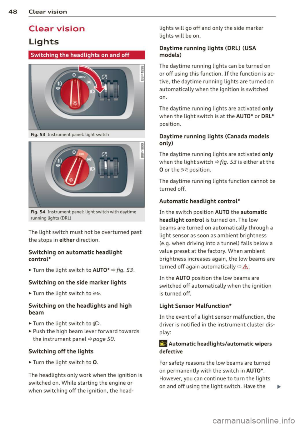
Fig . 53 Instr ument pane l: light sw itch
Fig. 54 Instr ument pane l: ligh t switch w ith dayti me
running lights (DR L)
The light switch must not be overturned past
the stops in
either direct ion.
Switching on automatic headlight
control*
.,. Turn the light switch to AUTO* ¢ fig. 53.
Switching on the side marker lights
... Turn the light switch to :;oo:.
Switching on the headlights and high
beam
... Turn the light switch to iD.
... Push the high beam lever forward towards
the instrument panel¢
page SO.
Switching off the lights
... Turn the light switch to 0.
The head lights only work when the ignition is
switched on. While start ing the engine or
when switching off the ignition, the head- lights
will go off and only the side ma rker
lights will be on.
Daytime running lights (DRL) (USA
models)
T he daytime running lights can be turned on
or off using this function. If the function is ac
tive, the daytime running lights are turned on
automatically when the ignit ion is switched
on.
The daytime running lights are activated
only
when the light switch is at the AUTO* or DRL *
position.
Daytime running lights (Canada models
only)
The daytime running lights are activated only
when the light switch ¢ fig. 53 is either at the
0 or the :;oo: position.
T he daytime r unning lights funct ion cannot be
turned off.
Automatic headlight control*
In the switch position AUTO the automatic
headlight control
is turned on. The low
beams are turned on automatically through a
light sensor as soon as ambient brightness
(e .g. when driving into a tunnel) falls below a
value preset at the factory. When ambient
brightness increases aga in, the low beams are
turned off again automatically ¢.&. .
In the
AUTO position the low beams are
switched off automatically when the ignition
is turned off .
Light Sensor Malfunction*
In the event of a light sensor malfunction, the
driver is notified in the instrument cluster dis
play:
El Automatic headlights/automatic wipers
defective
For safety reasons the low beams are turned
on permanently with the switch in
AUTO* .
However, you can continue to turn the lights
on and off using the light switch. Have the
Ill>-
Page 52 of 244
50 Clear vis ion
Front fog lights
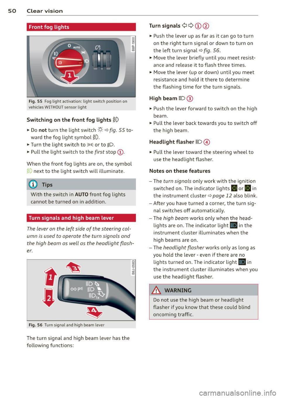
F ig. 55 Fog light act ivation: light switch pos itio n on
veh icles WITHOUT sensor light
Switching on the front fog lights iO
.,. Do no t turn the light switch ·'t/- · ¢ fig. 55 to-
ward the fog light symbol
}D.
.,. Turn the light switch to :o o: or to io .
.,. Pull the ligh t switch to the first stop @.
When the front fog lights are on, the symbol
}D next to the light switch will i llum ina te.
@ Tips
With the switch in AUTO front fog lights
cannot be turned on in addit ion.
Turn signals and high beam lever
The lever on the left side of the steering col
umn is used to operate the turn signals and
the high beam as well as the headlight flash
er .
Fig. 56 Tu rn signa l and hig h beam lever
The turn signal and high beam lever has the
following functions:
Turn signals ¢ Q ©@
.,. Push the lever up as fa r as it ca n go to t urn
on the right turn s ignal or down to tu rn on
the left turn signal ¢
fig. 56 .
.,. Move the lever briefly unti l you meet res ist
ance and release it to flash three times .
.,. Move the lever (up or down) until you meet
resistance and hold it there to determine
the flashing time for the turn signals .
High be am gD @
.,. Push the lever forward to switch on the high
beam.
.,. Pull the lever back towards you to switch off
the high beam.
Headlight fla sh er gD @
.,. Pull the lever toward the steering whee l to
use the headlight flasher.
Not es on thes e features
- The turn signals on ly work wi th the ignition
sw itched on. The indicator lights
F-1 or rl in
the instrument cluster¢
page 12 also blink.
- After you have turned a co rner, the turn s ig-
na l switches off automa tically .
- The
high beam works on ly w hen the he ad
lights a re on . The indicator light
II in t he
instrument cluster illuminates when the
high beams are on.
- The
headlight flasher works only as long as
you ho ld the lever - even if there a re no
lights turned on. The indicator light
II in
the instrument cluster illuminates when you
use the headlight flasher.
A WARNING
-
Do not use the h igh beam or head light
flasher if yo u know that these could b lind
oncom ing traffic.
-
Page 53 of 244
Emergency flasher
The emergency flasher makes other motorists
a w are that you or your vehicle are in an emer
gency situation.
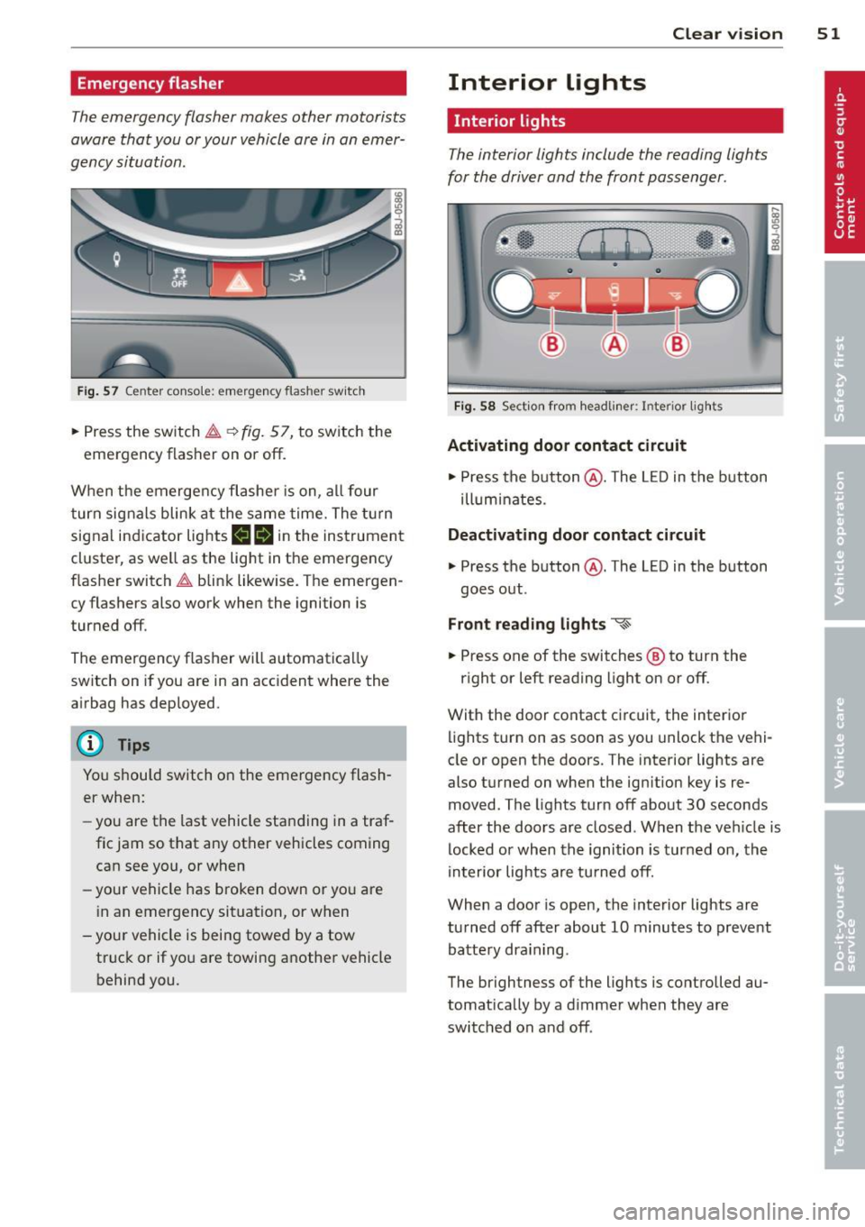
Fi g. 57 Center conso le: emergency flasher sw itch
.. Press the switch ~~ fig. 57, to switch the
emergency flasher on or off.
When the emerge ncy flashe r is on, al l four
turn signals blink at the same time. The t urn
signal indicator lights
II Hin the instrument
cluster, as we ll as the light in the emergency
flasher switch~ blink likewise. The emergen
cy flashers also work when the ignition is
turned off.
The emergency flasher will automatica lly
switch on if you are in an acc ident where the
airbag has deployed.
@ Tips
You should switch on the emergency flash
er when:
- you are the last vehicle sta nding in a traf
fic jam so that any other vehicles coming can see you, or when
- your vehicle has broken down or yo u are
i n an emergency situation, or when
-you r vehicle is being towed by a tow
truck or if yo u are towing a nothe r vehicle
behind you. Clear vi
sion 51
Interior lights
Interior lights
The interior lights include the reading lights
for the driver and the front passenger.
Fig. 58 Section from headli ner: Interior lights
Activating door contact circuit
.. Press the button @. The L ED in the button
ill um inates.
Deactivating door contact circuit
.. Press the button @. The LED in the button
goes out .
Front read ing lights ~
.. Press one of the switches ® to turn the
r ight or left reading light on or off.
With the door contact ci rcuit, the inter ior
lights turn on as soon as you unlock the vehi
cle or open the doors. The interior lights are
also turned on when the ignition key is re
moved. The lights turn off about 30 seconds
after the doors are closed . When the veh icle is
locked or when the ignition is turned on, the
in terior lig hts are tu rned off.
When a door is open, the inte rior lights are
tu rned off after about 10 minutes to preve nt
batte ry dra in ing.
The brightness of the lights is controlled au
tomat ica lly by a d immer when they are
switched on and off.
Page 72 of 244
70 Warm and cold
Setting fan sp ee d 8/r
.,. Turn the knob@¢ page 68, fig. 79 to the
setting you want to adjust fan speed (air
quantity).
I n a utomat ic mode the cl imate control sys
tem automatically regulates fan speed de
pending on interior temperature. You can ad
just the volume of air produced by the fan to
meet your own requirements.
Air distribution
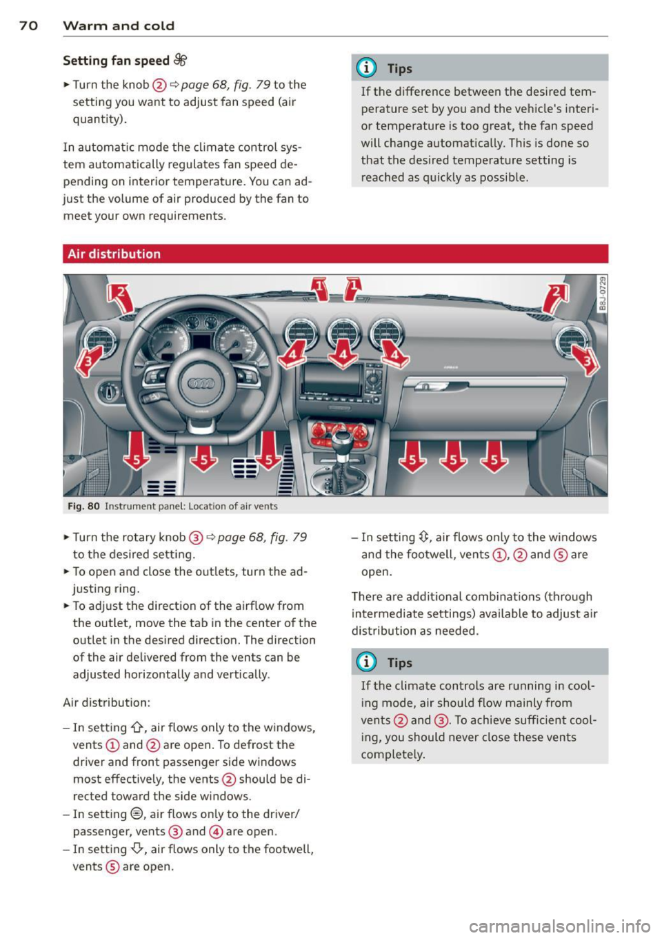
F ig . 8 0 In st rume nt panel: Locat ion of air vents
.,. Turn the rotary knob@¢ page 68, fig. 79
to the desired setting .
.,. To open and close the o utlets, turn the ad
justing ring .
.,. To adj ust the direct ion of the airf low from
the outlet, move the tab in the center o f the
outlet in the des ired d irect ion. The direction
of the air de livered from the vents can be
adjusted horizontally and vertically .
A ir distribution :
- In sett ing
-0-, air flows only to the w indows,
vents
(D and @are open . To defrost the
driver and front passenger side windows
most effectively, the vents @should be di
rected toward the side w indows.
- In sett ing@, air flows on ly to the dr iver/
passenger, vents ® and © are open.
- In setting{}, air flows only to the footwell,
vents ® are open .
(D Tips
If the difference between the desired tem
perature set by you and the veh icle's interi
or temperature is too great, the fan speed
will change a utomat ically. This is done so
that the desired temperature setting is
r eached as q uic kly as possib le.
- In setting~' air flows only to the windows
and the footwell, ven ts
(D , @ and ® are
open.
T he re a re additional comb inat ions (th ro ugh
in termediate settings) available to adjus t air
dist ribution a s needed.
(r} Tips
If the climate contro ls are running in cool
i ng mode, air should flow mainly from
vents @and @. To achieve sufficient co ol
i ng, you should never close these ven ts
complete ly .
Page 76 of 244
74 On the road
you leave your vehicle. This makes a vehicle
theft even more difficult ¢ .&. .
Ignition key saf ety lock
Afte r swi tching off the ignition, t he ig nit ion
key can on ly be removed from the ig nition
lock when the se lector lever is in the "P"
(Park) position . After you have removed the
key, the selector lever is locked and cannot be
moved.
Ignition on @
If it is diffic ult to tu rn the key after you have
inserted it into the ignition lock, turn the
steering wheel back and forth. This will take
the load
off the steering lock mechanism and
you will be able to turn the key freely and
start the engine.
Starting the engine @
In this position the engine starts . While the
engine is starting , the power supply to the
headlights and other e lectrica l consumers is
temporari ly interrupted to conserve battery
power. After the engine has started, release
the key and it will return to posit ion
(D .
Before the starter can be operated again the
key must be turned back to position @. The
non -repeat loc k prevents you from damaging
the starter when the engine is runn ing .
A WARNING
-Never remove the key from the ign it ion
lock whi le the vehicle is moving. The
steeri ng wheel will lock causing loss of
c ontrol.
- If you have to leave your vehicle - even
for just a m inute -always remove t he ig
nition key and take it with you. This is es
pecially important if you a re going to
leave chi ldren behind in the vehicle. The
children co uld start the engine or use
other vehicle controls. Unsupervised use
of vehicle controls (for examp le, power
windows) can cause serious personal in
jur ies .
(D Tips
If the vehicle battery has been disconnect
ed and then reconnected, then you must
l eave the key in position
(D for about 5
seconds before you can start the engine.
Starting and stopping
the engine
Starting the engine
The engine can only be started with an origi
nal Audi key.
.,. Set the park ing brake.
.,. Move the selector lever in P or
N ~ &_ .
.,. Turn the ignition key to position @
¢ page 73, fig. 82 -do not depress the gas
pedal when starting the engine!
.,. Let go of the key as soon as the engine
starts .
A cold engine may at first be loud after it has
been started. This is due to the hydraulic
valves bu ild ing up the oil pressure . Th is nor
mal and no need for concern .
If the engine does not start immediate ly, stop
trying after 10 seconds and then try to restart
the engine about 30 seconds later .
A WARNING
-Never start or let the engine run in a con-
f ined or enclosed area. Exhaust fumes
from the engine conta in carbon monoxide,
a colorless and odorless gas. Carbon mon
oxide can be fatal if inhaled .
- Never leave the engi ne idling unattend
ed. An unat tended veh icle w ith a runn ing
engine poses a danger of personal injury
or theft .
(D Note
-Avo id h igh engine speeds, fast accelera
tion or heavy engine loads while the en
gine is still cold. This could damage the
engine.
- T he engine cannot be started by pushing
or towing the vehicle . ..,.