set clock AUDI TT ROADSTER 2015 Owners Manual
[x] Cancel search | Manufacturer: AUDI, Model Year: 2015, Model line: TT ROADSTER, Model: AUDI TT ROADSTER 2015Pages: 244, PDF Size: 60.74 MB
Page 13 of 244
Instrument s and warning /indicator lights 11
Digital clock with date display
Your vehicle is equipped with a quartz con
trolled digital clock .
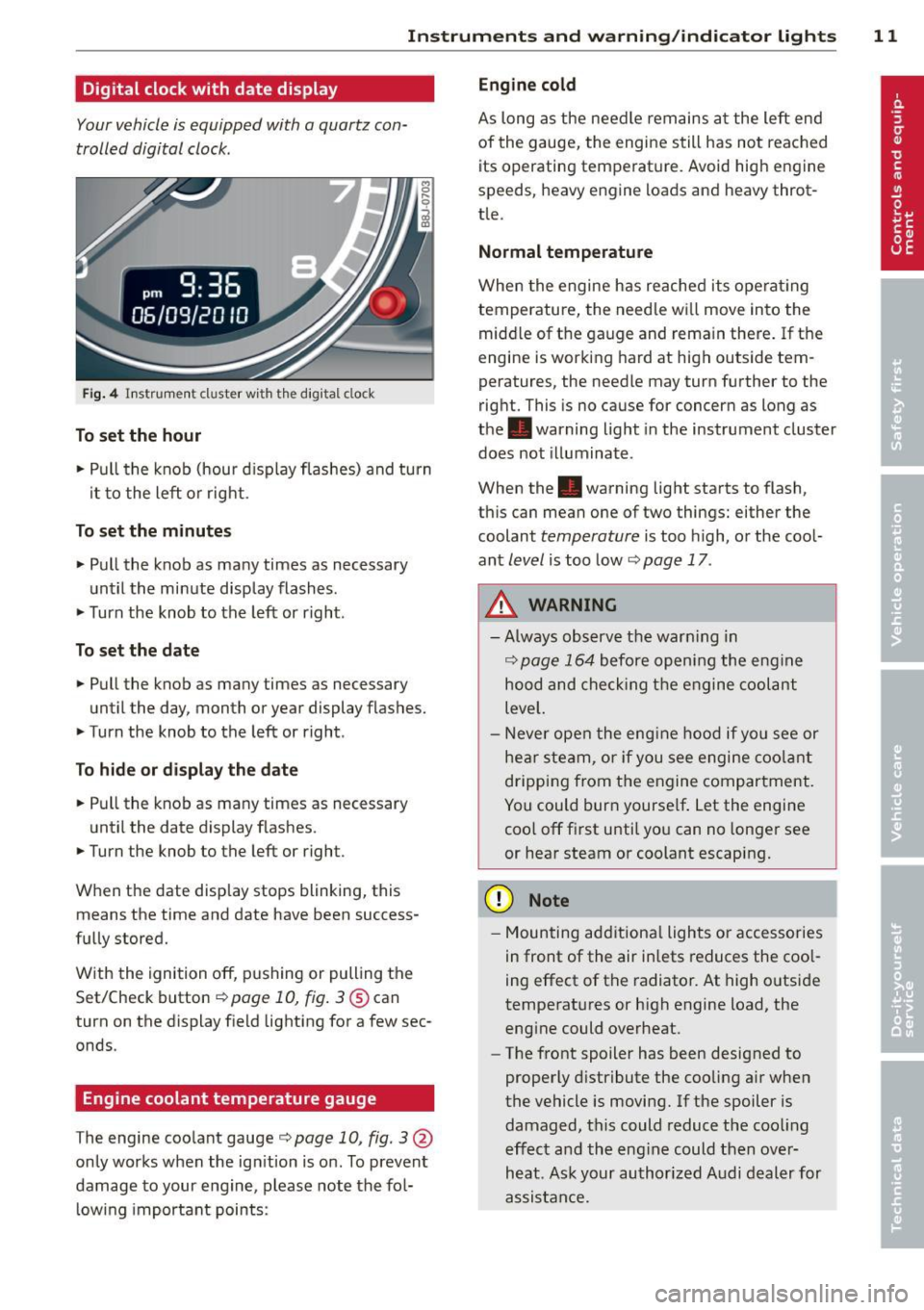
Fig. 4 In str um en t cl uste r w it h t he dig ita l cloc k
To set the hour
.. Pull the knob (hou r d isp lay flashes) and turn
i t to the left o r right.
To set the minutes
.. Pull the knob as ma ny times as necessary
un til the mi nute display flash es.
.. Turn the knob to the left or right .
To set the date
.. Pull the knob as many times as necessary
unt il the day, month or year display flashes.
.. Turn the knob to the left or right .
To hide or d isplay the date
.. Pull the knob as many times as necessary
unti l the date display flashes.
.. Turn the knob to the left or right.
When the date disp lay stops blinking, this
means the time and date have been success
fu lly stored.
W ith the ignition off, pushing or pulling the
Set/Check button¢
page 10, fig . 3@ can
turn on the dis play f ie ld lighting for a few sec
onds .
Engine coolant temperature gauge
The engine coo la nt gauge ¢ page 10 , fig. 3@
only works when the ign ition is on. To prevent
damage to your e ngine, please note the fo l
l owing important points:
Engine cold
As long as the nee dle rem ains a t the left end
of the gauge, the engine s till h as not reac hed
its operating temperat ure. Avoid high engine
speeds, heavy engine loads and heavy throt
tle.
Normal temperature
W hen the engine has re ache d its ope rat ing
temperature, the need le w ill move into the
mid dle of t he gauge and rema in there .
If the
engine is working hard at high outside tem
peratures, the needle may turn fu rther to the
right. This is no cause for concern as long as
the . warning light in the instrument cluster
does not illuminate .
When the. warning light sta rts to flash,
th is can mean one of two things: either the
coolant
temperature is too high, o r the coo l
ant
level is too low ¢ page 17 .
A WARNING
--Always obs erv e th e war ning in
¢ page 164 before openi ng the eng ine
h o od and che ck ing t he e ngine coolant
leve l.
- N ever open t he eng ine hood if you see or
he ar steam, or if you see engi ne coo lant
drippin g from t he en gine compar tment .
You could burn yourse lf . Let the engi ne
coo l off fi rst until yo u can n o longe r see
or hea r steam or coolant escap ing.
(D Note
- M ounting ad ditiona l lights or accessories
i n fr ont of the air inlets reduces the coo l
ing effect of t he radiato r. At high o utsi de
tempe rat ures or h igh engine load, the
eng ine could overheat.
- The front spoiler has been designed to
properly d istribute the cooling a ir when
the vehicle is movi ng. If the spoiler is
damaged, this could reduce the coo ling
e ff ect a nd th e eng ine could then ove r
heat . As k yo ur au thori zed A udi deal er for
a ssis tan ce.
Page 27 of 244
Set Clock ¢ page 2 5
Computer¢ page 25
Acoustic par k assist* ¢ page 79
Speed warning ¢ page 77
Language ¢
page 2 5
Units (distance, fue l consump-
tion, temperature) ¢
page 25
Tire press ure moni toring
c> page 198
Lap timer* c>page 28
Lighting* ¢ page 48
Wiper (service pos it io n)
¢page 56
Window c> page 40
Doors (unlo ck ing and locking
mode, for example Auto- lock)
¢ page 34, c> page 34
Check
Service c> page 28
Chassis numbe r c> page 2 22
Engine oil temperature*
¢
page 26, c> page 26
Registe red keys ¢ page 32
Menu off
All of the messages shown in
vehicles withou t menu display ap-
pe ar o n the display screen.
Navigating the menu
Use the rocker switch on the windshield wiper
lever and the
I Reset ! button to operate the
menu and carry out inquiries and selections.
~-- @
Fig. 1 2 Wiper leve r: Controls for the men u disp lay
To open the menu
.. Press the I Reset ! button @ until the menu
display
i=> page 24 , fig . 11 appears
Dr iver in formation system 25
Selections and settings
.. Press the rocker switch @to reac h a men u
disp lay. The swi tch is operated the same as
the display (up/down).
Entering and confirming
.,. Press the I Reset I butto n @ .
Returning to the Start menu
.. Press the I Reset I button longer tha n 2 sec
onds to return from any menu level to the
Sta rt menu .
U sing the rocker switc h, you can select the
menus in the display or change settings. A
cursor appea rs on the left in front of these
lected values .
By pressing the
I Reset! button, you activate
the selection you made or confirm the values
you set.
Selected fu nctions are identified wit h
a check mark or ar e car ried out directly .
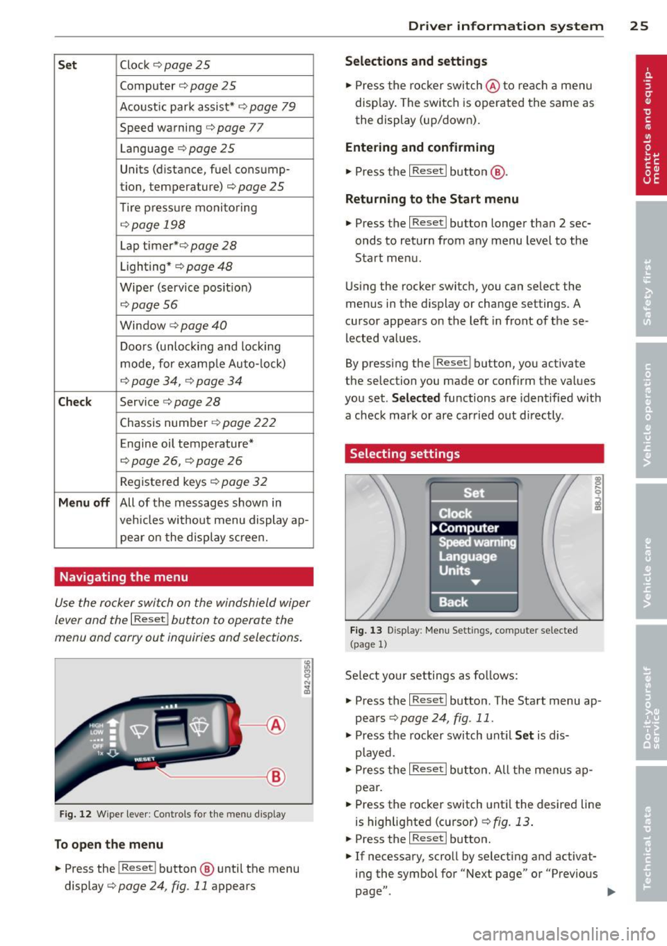
Selecting settings
Fig. 13 D isplay: Menu Sett ings, co mpute r selected
(page
l)
Se lect you r settings a s foll ows:
.,. Press the
I Reset I butto n. The Sta rt menu ap
pears ¢
page 24 , fig . 11 .
.. Press the rocker switch unt il Set is dis
played .
.. Press the
I Reset I butto n. All the menu s a p
pe a r .
.. Press the rocker switch until the desire d line
is highlig hted (curso r)
¢ fig . 13 .
.. Press the I Reset I button.
.. If necessary, scro ll by selecting and activat
ing the symbol for "Next page" o r "Previous
page" .
~
Page 79 of 244
Speed warning 2: setting a speed limit
Switches in the wiper arm are used to operate warning threshold
2 .
'----I ®
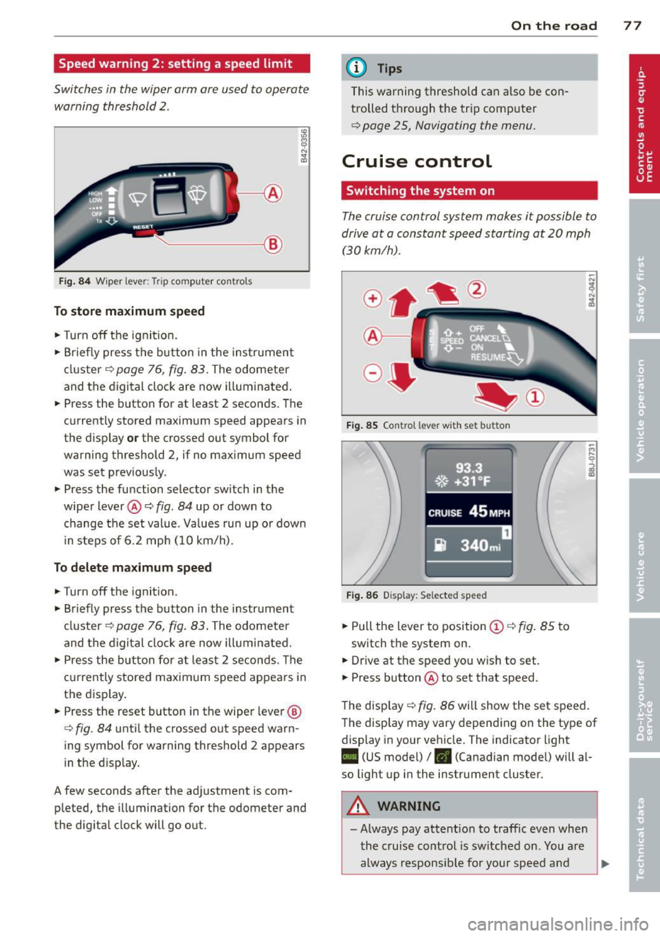
Fig. 84 W iper lever: Trip computer controls
To store maximum speed
.. Turn off the ignit ion .
.. Briefly press the button in the instrument
cluster¢
page 76, fig. 83. The odometer
and the digital clock are now illuminated .
.. Press the button for at least 2 seconds. The
currently stored maximum speed appears in
the display
or the crossed out symbol for
warning threshold 2, if no maximum speed
was set previously .
.. Press the function selector switch in the
wiper lever@¢
fig. 84 up or down to
change the set value. Values run up or down
i n steps of 6.2 mph (10 km/h).
To delete maximum speed
.. Turn off the ignition.
.. Briefly press the button in the instrument
cluster ¢
page 76, fig. 83. The odometer
and the digital clock are now illuminated.
.. Press the button for at least 2 seconds. The
currently stored maximum speed appears in
the display.
.. Press the reset button in the wiper lever®
¢
fig . 84 until the crossed out speed warn
ing symbol for warning threshold 2 appears
in the d isplay.
A few seconds after the adjustment is com pleted, the illumination for the odometer and
the digital clock will go out.
On the road 77
@ Tips
This warning threshold can a lso be con
trolled through the trip computer
¢ page 25, Navigating the menu.
Cruise control
Switching the system on
The cruise control system makes it possible to
drive at a constant speed starting at
20 mph
(30kmlh).
®-
Fig. 85 Co ntro l leve r w ith set b utto n
Fig. 86 Display : Se lected speed
.. Pull the lever to position @¢ fig. 85 to
switch the system on .
.. Dr ive at the speed you w ish to set .
.. Press button @ to set that speed.
The display ¢
fig. 86 will show the set speed .
The display may vary depending on the type of
display in your vehicle. The indicator light
II (US model) /. (Canadian model) will al
so light up in the instrument cluster .
A WARNING
-Always pay attention to traffic even when
the cruise control is switched on. You are
always responsible for your speed and
Page 212 of 244
210 What do I do now?
slip and cause an injury if it does not
have sufficient hold on the vehicle.
- A soft or unstable surface under the
jack may cause the vehicle to slip off
the jack. Always provide a firm base for
the jack on the ground . If necessary,
use a sturdy board under the jack.
- On hard, slippery surface (such as tiles)
use a rubber mat or similar to prevent
the jack from slipp ing .
- To help prevent injury to yourself and
your passengers:
- Do not raise the vehicle unti l yo u are
sure the jack is securely engaged.
- Passengers must not remain in the ve
hicle when it is jacked up.
- Make sure that passengers wait in a
safe p lace away from the vehicle and
well away from the roadway and traffic.
- Make sure jack position is correct, ad
just as necessa ry and then continue to
ra ise the jack .
(D Note
A floor jack or the pads on the hoist arms
must
not be posit ioned at the points
shown
-arrows- .
Taking the wheel off
Follow these instructions step-by-step for
changing the wheel.
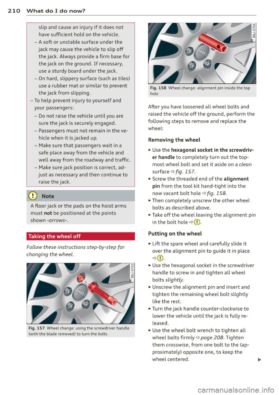
Fig. 157 Wheel ch an ge: us ing the sc rewdrive r hand le
(w ith the b lade removed) to turn the bolts
Fig. 158 Whee l change : alignmen t pin inside the top
hol e
After you have loosened all wheel bolts and
raised the vehicle off the ground, perform the
following steps to remove and replace the
wheel:
Removing the wheel
.,. Use the hexagonal socket in the screwdriv
er handle
to completely turn out the top
most whee l bolt and set it aside on a
clean
surface c;, fig. 15 7.
.,. Screw the threaded end of the
alignment
pin from the tool kit hand-tight into the
now vacant bolt hole <=>
fig. 158 .
.,. Then completely unscrew the other wheel
bolts as described above.
.,. Take off the whee l leaving the alignment pin
in the bolt hole
c;,(D .
Putting on the wheel
.,. Lift the spare wheel and carefully s lide it
over the alignment p in to guide it in place
c;,(D .
.,. Use the hexagonal socket in the screwdriver
handle to screw in and tighten all whee l
bolts
slightly .
.,. Unscrew the alignment p in and insert and
tighten the remaining wheel bolt slightly like the rest .
.,. Turn the jack handle counter-clockwise to
lower the vehicle until the jack is fully re
leased .
.,. Use the wheel bo lt wrench to tighten all
wheel bolts firmly ,=:,
page 208 . Tighten
t hem
crosswise, from one bolt to the ( ap
proximately) opposite one, to keep the
wheel centered.
Page 233 of 244
_______________________________ ___:I~n ~d ~e:.::x 231
Temperature ... ... .... ... .. .. .. .... 68
Venti lation ..... .. .... ... .. .. .. .... 67
C lock ..... ................... .. ....
11
Clutch overheating . . . . . . . . . . . . . . . . . . . 86
Cold tire inflat ion pressure ... .. .. .. .. .
184
Com ing home .............. ... ... ... 49
Compass m irror . ....... ... .. .. .. .. .. 58
Comp lian ce .. ............. .. .. .. ... 228
Consumer Info rmat ion . . . . . . . . . . . 98, 225
Contact ing NH TSA . ..... ... .. .. .. .. .. 98
Controls Cleaning . .. .. ........... .. .. .. ...
156
Controls and d isp lays ....... .. .. .. .. .. . 8
Convenience close/open feat ure
Powe r top . . . . . . . . . . . . . . . . . . . . . . . . .
43
Windows . ..... ...... ... .. .. .. .... 40
Conve rtible c hild safety sea ts .. .. .. .. .
134
Convertible locking retractor
Activating . . . . . . . . . . . . . . . . . . . . . . . .
139
Deactivating ................ .... .. 139
Using to secure a ch ild safety seat 137, 139
Convertible top . ........... .. .. .. .. .. 41
Au tomatic convertible top .. .. .. .. .. .. 43
Emergency operation ........... .... . 44
Ge ne ral i nfo rmation .......... ... ...
41
manual conve rtib le top .. ... . .. ... ... 42
War ning/ indic to r l igh ts .... .. .. .. .. ..
1 7
W ind deflecto r ........... .... .. .. .. 44
Cooling system . . . . . . . . . . . . . . . . . . . . .
1 71
Expansion ta nk ... ... ... .. .. .. .. .. . 172
Cornering light ............ .... .. .. .. 49
Cruise control . . . . . . . . . . . . . . . . . . . . . . . 77
Changing spee d . . . . . . . . . . . . . . . . . . . . 7 8
Presetting your speed . . . . . . . . . . . . . . . 78
Sw itching
off .... ..... ... .. .. .. .... 78
Sw itching on . . . . . . . . . . . . . . . . . . . . . . . 77
War ning/ indicator lights ... .. .. .. .. ..
21
Cup holder . . . . . . . . . . . . . . . . . . . . . . . . . . 63
Current fuel m ileage
23
D
Damping
refer to Audi magnetic ride ... .. .. .. .. 79
D ata recorder . ..... .... ... .. .. .. ... 14 1
Date display . . . . . . . . . . . . . . . . . . . . . . . . 11
Daytime running lights .... .. .. .. .. .. .. 48
Decla rat ion of compliance
Ce ll phone package .. ... .... ... .. .. 228
E lectronic immob ilizer .. ..... ... .. .. 228
Homelink universal remote control . .. 228
Remo te contro l key ... ............. 228
Decorative deca ls
Cleaning . ... .... ... .. .. ..... ... ..
156
Decorative pa rts/tr im
Cleaning .. .. .. .. .... .............
156
def
What does this mea n when it appears in
the tr ip odometer display? ...........
12
Defective light bulb warning . ....... .. . 20
Defrost ing the w indows . .... ..... .. .. . 70
Determ ining correct load limit ........
189
Digital clock . . . . . . . . . . . . . . . . . . . . . . . . 11
D . · l 1g1ta compass . . . . . . . . . . . . . . . . . . . . . 58
Dimens ions . .. .. .. .... ............. 223
D imming the rearview m irror .. ... .. .. . 53
D ipst ick
Reading the d ipst ick properly ........
169
Displays
Cleaning
156
Distance ... .. .. .... . ... ...... ... .. . 23
Driver informat io n system
Boost ........ .. .. ... ....... ...... 26
E ngine oi l tempera ture .. ..... .. .. .. . 26
Menu but to n .. .. ... ..... ..... .. .. . 25
Menu disp lay . . . . . . . . . . . . . . . . . . . . . . 24
Open door or front lid warning ... .. .. . 22
Outsid e temperature disp lay . . . . . . . . . . 22
Serv ice inte rval display . . . . . . . . . . . . . . 28
Se tting ... .. .. .. .... ...... ....... . 25
Sound system display ... .... ... .. .. .
22
T' np compute r .. .. .. ................ 23
Dr iver seat
refer to Seating position . ..... .. .. .. . 92
Drivi ng
Run -flat t ires . ..... . .. .. ..... ... .. 20 2
Drivi ng safely ...... ........... ......
91
Driving throug h wate r .. .. .. .. ... .. .. 150
D upli cate key . .. .. .... ... .... ...... . 32
Dus t fil ter . . . . . . . . . . . . . . . . . . . . . . . . . . 68
•
•
Page 238 of 244
236 Index
Proper seating position Front passenger . . . . . . . . . . . . . . . . . . . . 93
Occupants . .... ............ .. .... .. 92
Protecting . .. .... .. ... .... .. .. .. .. . 156
Q
Quartz clock . . . . . . . . . . . . . . . . . . . . . . . . 11
quatt ro
refer to All-wheel dr ive .... .. .. .... . 146
Question What happens to unbe lted occupants? 101
Why safety be lts? . . . . . . . . . . . . . . . . . 100
R
Radiator fan .... . ...... ... .. .. .... . 173
Ra in sensor defect ive .... .... .... ..... 21
Reading lights .... ..... ...... .. .. .. .. 51
Rear lid . .. .. .... .... ..... .. .. .. .. .. 37
E mergency release . . . . . . . . . . . . . . . . . . 38
Rear lig ht defective . . . . . . . . . . . . . . . . . . 20
Rear spoiler . . . . . . . . . . . . . . . . . . . . . . . . 143
Rear v iew mirro r . . . . . . . . . . . . . . . . . . . . . 53
Rear window defogger . . . . . . . . . . . . . . . . 70
Refue lling ... ... . ...... ... .. .. .... . 162
Release lever for hood .......... .. ... 164
Remote control . . . . . . . . . . . . . . . . . . 33, 36
Remote control garage door opene r
( H omelink) . . . . . . . . . . . . . . . . . . . . . . . . . 88
Remote master key Un lock ing and locking ..... .. .. .. .. . . 35
Remote rea r lid release . .... .. .. .. .. . . 37
Repair manua ls .. .. ..... ... .. .. .... . 225
Repairs Airbag system ............ ... .. .. . 12 1
Replacement parts ........... .. .. .. . 227
Replacing Wheel rims .... .. ..... ... .. .. .... . 19 1
Replacing a fuse .... ... .. .. .. .. .. .. . 212
Replacing light bulbs ....... .. .. .... . 215
Replacing tires a nd wheels ... .. .. .. .. . 19 2
Replacing w indshield wiper blades .. .. . . 57
Report ing Safety Defects . ... .. .. .... . . 98
Reset b utton . ............. .. .. .. .. .. 12
Resett ing remote control .... .. .. .. .. . . 36
Retractor .... ... ... .... ... .. .. .... . 103 Reve
rse (A utomat ic transm iss ion) . ... .. . 81
Rims Cleaning .. .... .. ............. .... 156
Rep lac ing . .. .. .. ............. .. .. 191
Run-fl at t ires .. .. .. .. .. ...... ... .. .. 201
Driving ....... .. .. ... ........... . 202
Introduction ..... ................ . 201
Replac ing defects pa rts ......... .. .. 203
s
SAFE .. ..... ... .. .. ... ........... .. 12
Saf e driving habits ... ... ..... ... .. .. . 91
Safety be lt pos ition ............. .... 104
Safety be lts worn by pregnan t women 105
Safety be lt pretensioner
Se rv ice and d isposal ... .. ... ..... .. 106
Safety be lts . .. .. .. ............. .. .. 103
Cleaning .. .. .. .. ... ...... .... .... 157
Danger to passengers who do not wear a
safety belt .. .. .. .......... ...... . 101
Fastening ... .. .. ... .. .. ... ..... .. 103
Improperly worn . ................. 105
Not worn . .... .. ............. .... 101
pretensioners .. .. ............. .... 106
Safety be lt pos ition .. .. ..... ... .. .. 104
Safety i nstr uctions . .... ..... ... .. .. 102
Securing child safety seats . ... .. .. .. 137
Spec ial considerations for pregnant
women ... .... .. .. ............... 105
U nfastening ... ... ................ 105
Warning/ind icator light ............ . 100
Why YOU MUST wea r them .. .. .. .. .. 100
Worn p rope rly . .. ............. .. .. 102
Safety be lt warning light . . . . . . . . . 16, 100
S afety comp liance s ticker ..... ... .. .. 222
Safety eq uipme nt .. ................ .. 91
Safety features for occ upant restraint and
protection .. .... .. ............. .... . 91
Safety gu idelines
Seat adjustment. . . . . . . . . . . . . . . . . . . . 59
Safety instr uctions
E ngine compartment ... ... ..... .. .. 164
for using ch ild safety seats ...... .. .. 132
F or usi ng sa fe ty belts .......... .. .. 102
Monito ring the Advanced Airbag Sys -
tem . ... .. .... .. .. ... .. ..... ... .. 120
Safety lock (Ignition k ey) . . . . . . . . . . . . . . 73
Page 239 of 244
Seat adjustment Driver's seat . . . . . . . . . . . . . . . . . . . . . . . 59
Front passenger's seat . . . . . . . . . . . . . . . 60
Front seats . . . . . . . . . . . . . . . . . . . . . . . . 59
Head restraints .......... .... .. .... 94
Head restraints, front seat . . . . . . . . . . . 62
Manual controls . . . . . . . . . . . . . . . . . . . . 60
Power seats ................ .... ... 61
Safety guidelines ......... .. .. .. .. .. 59
Seat covers Cleaning . ............ ...... .... .. 157
Seating capacity
Seating position 100
Driver ... .. .... ............. .. .. .. 92
F ront passenger .......... .... .. .... 93
How to adjust the front seats . . . . . . . . . 93
Incorrect seat position . . . . . . . . . . . . . . . 95
Occupants .. ................ ... .... 92
Seats Number of seats ......... .. .. .. .. . 100
Selector lever emergency release . . . . . . . 86
Selector lever positions ........ ... .. .. 81
Service and disposal
Safety belt pretens ioner ... .. .. .. .. . 106
Service interval display . . . . . . . . . . . . . . . . 28
Service position for windshield wipers ... 56
Set menu .. .. ... .. ..... ... .. .. .. .. .. 25
Setting Date display . . . . . . . . . . . . . . . . . . . . . . . 11
Digital clock ................ .... ... 11
Shutting down vehicle ......... ... .. . 151
Side airbags Description .............. .... .. .. . 125
How they work ........... .. .. .. .. . 126
Side marker lights .............. .... . 48
Ski bag . ..... .. ................ ..... 62
Snow chains . ............. .. .. .. .. . 196
Sockets ... .. .. ............. .. .. .... 64
Sound system display . . . . . . . . . . . . . . . . . 22
Sources of information about child re-
straints and their use . . . . . . . . . . . . . . . . 140
Speedometer ............. .... .. .... 12
Speed rating letter code ........ ... .. . 192
Speed warning system .......... ... ... 75
Sport button . . . . . . . . . . . . . . . . . . . . . . . . 79
Sport mode . . . . . . . . . . . . . . . . . . . . 79, 143
Index 237
Starting assistance ................. . 217
Starting the engine . . . . . . . . . . . . . . 72, 73
What should I do if the engine does not sta rt? .. .. .. .. .. .... ........... .. . 73
Steering
refer to Electro -mechanical power as-
sist ......... ... .. ........... 17,145
Steering column Adjusting . . . . . . . . . . . . . . . . . . . . . . . . . 72
Locking the steering . . . . . . . . . . . . . . . . 72
Steps for determining correct load limit . 189
Stopping the engine .. .............. .. 74
Storage .... .. .. .. .. .. ........... .. . 65
Compartment in the front seats . . . . . . . 65
Cup holder ...... .. ..... ........... 63
Glove compartment . . . . . . . . . . . . . . . . . 65
S tronic ..... ..... .................. 81
Driving Notes .. .. ............... .. . 83
Emergency program ........... .... . 86
Emergency release . . . . . . . . . . . . . . . . . . 86
Kick-down . . . . . . . . . . . . . . . . . . . . . . . . . 85
Launch Control Program ........... .. 85
Se lector lever lock . . . . . . . . . . . . . . . . . . 82
Selector lever positions ......... .. .. . 81
Tiptronic .... .. .. ................. . 84
Tiptronic controls on the steering wheel 85
Sun visors ........ .. ..... ........... 54
T
Tachometer . . . . . . . . . . . . . . . . . . . . . . . . . 10
Tail lights Cleaning ... ... .. .. .............. .
Tank flap
Unlocking the fuel filler flap by hand ..
Technical Data ...... ...... ......... .
Technical modifications
Temperature display 155
163
222
228
Engine oil . . . . . . . . . . . . . . . . . . . . . . . . . 26
Textiles Cleaning ......... ................ 157
The first 1,000 miles (1,500 km) and after-
wards ...... .. .. .. ................. 149
Tightening wheel bolts ........... .... 208
Tire mobility system ..... ....... .... . 205
Tire pressure . . . . . . . . . . . . . . . . . . . . . . . 186
•
•