trip computer AUDI TT ROADSTER 2015 Owners Manual
[x] Cancel search | Manufacturer: AUDI, Model Year: 2015, Model line: TT ROADSTER, Model: AUDI TT ROADSTER 2015Pages: 244, PDF Size: 60.74 MB
Page 4 of 244
2 Table of contents Vehicle literature .. .. .. .. .. ... .
About this Owner's Manual ...
Controls and equipment .. ... .
Cockpit ................ .... .. . .
General illus tration .... ... .. .. ... .
Instruments and warning/
indicator lights ........ .. .. .. . .
Ins truments . .. .. ..... ... .. .. ... .
War ning/ indi cator lights ... .. ... .. .
Driver information system .. .
Introduct ion . .. .. ..... ... .. .. ... .
Trip computer .. .. ..... ... .. .. ... .
M enu display . ........... .... ... .
Efficiency program ........ .. .. .. . .
Service interval d isp lay ..... ... .. . .
Lap timer .. .......... ........ .. .
On- Board Diagnostic system (OBD) .. .
Opening and closing .. .. .. .. . .
Keys ........................ .. .
P owe r locking system ............ .
R ear lid/ trun k li d ................ .
Ant i- t heft ala rm system ... .. .. .. . .
P owe r win dows .. ..... ... .. .. ... .
Convertible top .............. .
Convertible top ....... ... .. .. ... .
W ind Deflector . .. ..... ... .. .. ... .
Conve rtible top eme rgency o peration .
Clear vision .. .. ..... ... .. .. ... .
Lights ...... .. .. ..... ... .. .. ... .
Inter ior lights .. . ...... ... .. .. ... .
V1s1on . .. ................. .. ... .
W iper and washer system .. .. .. ... .
D ig ita l compass ........... .... .. .
Seats and storage ....... .. .. . .
Ge neral recommendat ions ........ .
Ad just ing front seats manually .. ... .
5
6
8
8
8
1 0
1 0
12
2 2
22
23
24
27
28
28
30
32
32
34
37
3 8
39
4 1
41
44
4 4
4 8
48
51
52
54
58
59 59
60
P owe r seats . . . . . . . . . . . . . . . . . . . . . 6 1
H ead res traints . . . . . . . . . . . . . . . . . . 6 2
L uggage compartmen t . . . . . . . . . . . . 6 2
Cup holder . . . . . . . . . . . . . . . . . . . . . . 63 Asht
ray ... .... .. ... .. ..... .... . .
Cigarette lighter/socket . ..... ... .. .
Storage ... .. .. .. .. ... .. .. .. .. .. .
Warm and cold ... .. ..... .... . .
Climate controls .. .. .... .... ... .. . 63
64
65
67
67
On the road
. . . . . . . . . . . . . . . . . . . 72
Stee ring . ..... .. ... .. ..... ... .. .
Ignition lock and ignition sw itch .. .. .
Starting and stopping the engine ... .
Parking brake ................... .
Speed warning system ............ .
Cru ise cont ro l .. .. ............... .
Audi magnet ic r ide ... ... .... ... .. .
Spo rt m ode .................. .. .
A coustic parking sys tem
Transmission .. .. ........... .. .
S t ronic transmission ........... .. .
72
72
73
74
75
77
79
79
79
81
81
Homelink . . . . . . . . . . . . . . . . . . . . . 88
U nivers al remote control ...... .. .. .
Safety first ................... .
Driving Safely .... .......... .. .
Gener al notes .. .. ............. .. .
P roper occ upan t seating positions . . .
Drive r and passenger side footwe ll .. .
Pedal a rea ..... .. .. ... ..... ... .. .
Stow ing luggage . ............. .. .
Reporting Safety Defects ........ .. .
88
9 1
91
91
92
95
96
96
98
Safety belts . . . . . . . . . . . . . . . . . . . 100
General notes . . . . . . . . . . . . . . . . . . . . 100
Why safety belts? . . . . . . . . . . . . . . . . 101
Safety be lts . . . . . . . . . . . . . . . . . . . . . 103
Safety belt pretensioners . . . . . . . . . . 106
Airbag system . . . . . . . . . . . . . . . . . 108
Important th ings to know . . . . . . . . . . 108
Front air bags .. .. ... .. ....... ... . 112
Moni to ring the Advanced Ai rbag
S ystem . . . . . . . . . . . . . . . . . . . . . . . . .
118
Page 24 of 244
22 Driver in formation sy ste m
Driver information
system
Introduction
The Driver information display inside the in
strument cluster provides you, the driver ,
with important information.
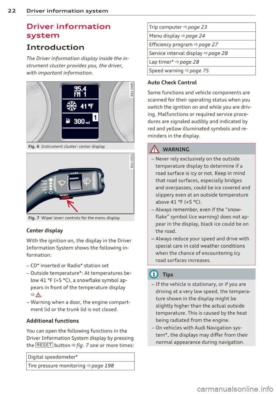
Fig . 6 In strum en t cl ust er: center display
Fig. 7 Wiper le ver: con trols fo r the menu disp lay
Cent er d ispla y
With the igni tion on, the display in the Dr iver
I nformation System shows the fol low ing in
formation :
- CD* inserted or Radio* station set
- Outs ide temperature* : At temperatures be-
low 41 °F ( +S °C), a snowflake symbol ap
pears in front of the temperatu re d isplay
c::> .&_ .
- Warning when a door, the engine compa rt-
ment lid or the trunk lid is not closed .
Additional functions
You can open the following functions in the
Driver Information Sys tem disp lay by p ressing
the
! R ESE T I button c::> fig. 7 one or more times:
Digital speedometer *
T ire pressure monitoring
c::> page 198
Trip computer c::> page 23
Menu d isplay c::> page 24
Efficiency program c::> page 27
Service interval disp lay
c::> page 28
Lap timer* c::> page 28
Speed warn ing <=:> page 75
Auto Check Control
Some f unct ions and vehicle components are
scanned for their operati ng sta tus when yo u
switch the ign ition on and whi le you a re driv
ing. Malfunctions or req uired service proce
dures ar e signaled audib ly and indicated by
red and yellow i lluminated symbols and re
m inders in the display.
A WARNING -
- Never rely exclusively on the outside
temperature display to determine if a
road surface is icy or not . K eep in m ind
that road surfaces, espec ially br idges
and overp asses, co uld be ice covered and
slippe ry even at an outside tempe ra tu re
above 4 1 °F (+5 °C).
- Always remembe r, even if the "snow
f lake" symbo l (ice warning) does not ap
pear in the disp lay, black ice could be on
the road .
- A lways reduce your speed and d rive with
specia l care in cold weather cond itions
when the chance of encountering icy
road surfaces increases.
(D Tips
- If the vehicle is stationary, or if you are
dr iving at a very low speed, the tempera
t u re s hown in the d isp lay m ight be
slightly h igher than the actual o utside
temperature. Th is is caused by the heat
being radiated from the engine .
- On vehicles with Audi Nav igat ion sys
tem *, the displays may differ from their
normal appearance during navigation .
Page 25 of 244
Trip computer
Introduction
The trip computer gives you information on
current and average fuel mileage, average
speed, fuel range and driving time .
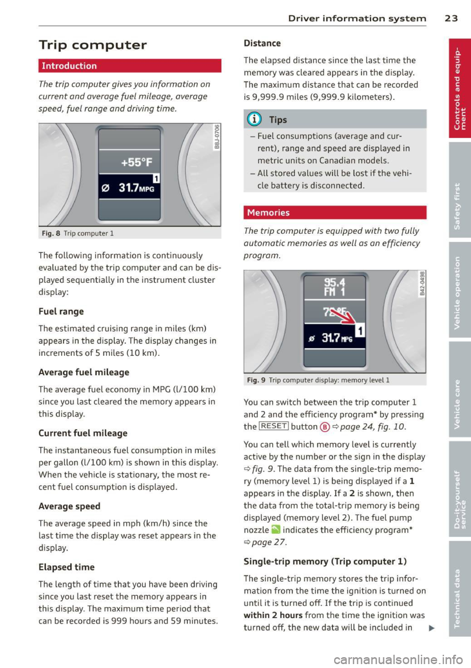
Fig. 8 T rip comp ute r 1
The fo llow ing informa tion is cont inuo usly
eva luated by the trip compu ter and can be dis
p layed sequentia lly in the instrument cl uster
d isplay:
Fuel range
The estimated c ruising ra nge in miles (km)
appears in the d isplay . The disp lay changes in
increments of 5 miles (10 km) .
Average fuel mileage
The average fue l economy in MPG (l/ 100 km)
since you last clea red the memory appears in
t his display .
Current fuel mileage
The instantaneous fuel consumption in miles
pe r gallon (l/ 100 km) is shown in this d isp lay .
When the ve hicle is stationary, the most re
cent fuel consumpt io n is displayed.
Average speed
The average speed in mph (km/h) since the
last time the display was reset appears i n the
d isp lay.
Elap sed t ime
The length of time that you have been driving
since you las t reset the memory appears in
this display . The maximum t ime period that
can be recorded is 999 ho urs and 59 minutes .
Driver in formation system 23
Distance
The elapsed dis tance sin ce the las t time the
memory was cleared appears in the d isp lay .
T he maxim um distance that can be recorded
is 9 ,999.9 miles (9,999 .9 k ilometers) .
(D Tips
- Fuel consump tions (average and cur
rent), range and speed are disp layed in
metric un its on Canadian mode ls.
- All sto red val ues wil l be lost if t he vehi
cle battery is d isconnected .
' . Memories
The trip computer is equipped with two fully
automatic memories as well as on efficiency
progrom.
Fi g. 9 Trip co mputer d isplay: memo ry level 1
You can switch between the trip computer 1
and 2 and the efficiency program* by pressing
the
I R ES ET I button @ c::> page 24, fig . 10 .
You can tell wh ich memory leve l is currently
active by the number or the sign in the display
c::> fig . 9. The data from the single-trip memo
ry (memo ry level 1) is being displayed if a
1
appea rs i n t he display . If a 2 is shown, then
the data from the total- trip memory is being
displayed (memory level 2). The f ue l pump
nozzle
ii indicates the efficiency program *
c::>poge 27.
Single-trip memory (Trip computer 1 )
The sing le -t rip memory stores the tr ip info r
ma tion from the time the ig nition is tu rned on
u nt il it is tur ned off. If the tr ip is cont inued
within 2 hour s from the time the ignit ion was
turned off, the new data will be included in ..,.
Page 26 of 244
24 Driver information system
the calculation of the current trip informa
t ion. If the trip is interrupted for
more than 2
hours
the memory is reset automatica lly.
Total -trip memory (Trip computer 2)
Unlike the sing le-trip memory, the total-trip
memory is not reset automatically. This per
mits you to evaluate your dr iving data for the
entire period between manual resets.
Efficiency program*
The effic ien cy program can help you to use
less fuel
~ page 2 7.
Operation
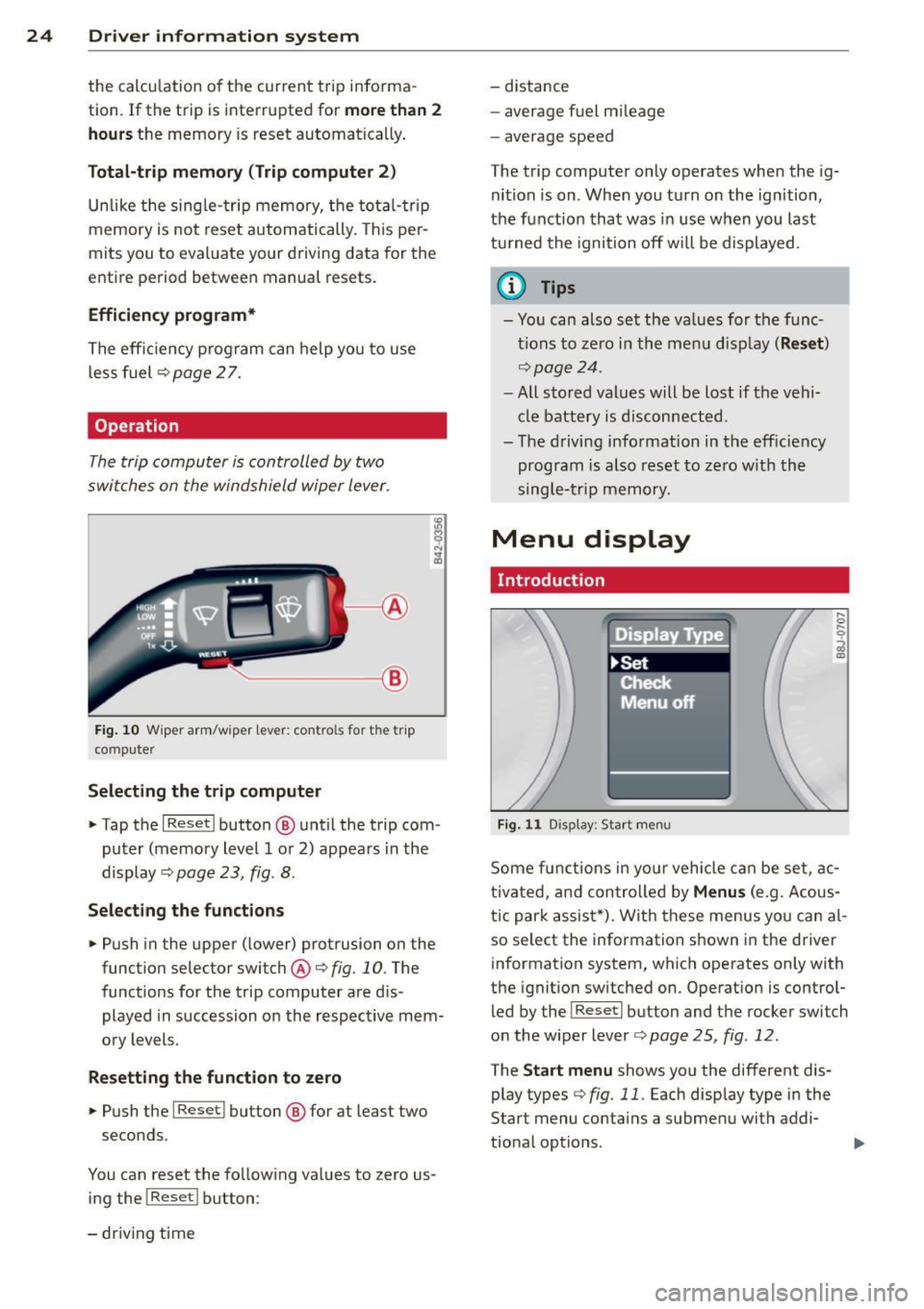
The trip computer is controlled by two
switches on the windshield wiper lever.
-----------< @
Fig. 10 W iper arm/w iper lever: con tro ls for t he trip
compute r
Selecting the trip computer
"Tap the I Reset I button @ until the trip com
puter (memory level 1 or 2) appears in the
display ¢
page 23, fig . 8.
Selecting the functions
" Push in the upper (lower) protrusion on the
function selector switch @
q fig. 10. The
functions for the trip computer are d is
played in succession on the respective mem
ory levels.
Resetting the function to zero
" Push the I Reset I button @ for at least two
seconds.
You can reset the fo llowing values to zero us
ing the
I Reset I button :
- driving time -
distance
- average f uel mileage
- average speed
The t rip computer only operates when the ig
nition is on. When you turn on the ignition,
the function that was in use when you last
turned the ignition off will be displayed .
(D Tips
-You can also set the values for the func
tions to zero in the menu display
(Reset )
qpage24 .
-All stored values will be lost if the vehi
cle battery is disconnected .
- The driving information in the efficiency
program is a lso reset to zero with the
single-trip memory.
Menu display
Introduction
Display Type
•set
iF'Cf t -,,., ==
Menu off
Fig. 11 D isplay: Sta rt men u
Some funct ions in yo ur vehicle can be set , ac
t ivated, and controlled by
Menus (e.g. Acous
tic park assist *). With these menus you can al
so select the information shown in the driver
information system, which operates only with
the ignition switched on. Operation is control
led by the
! Reset I button and the rocker switch
on the wiper lever
q page 25, fig . 12.
The Start menu shows you the different dis
play types
q fig . 11 . Each display type in the
Start menu contains a submenu with addi
tional options .
Page 29 of 244
Efficiency program
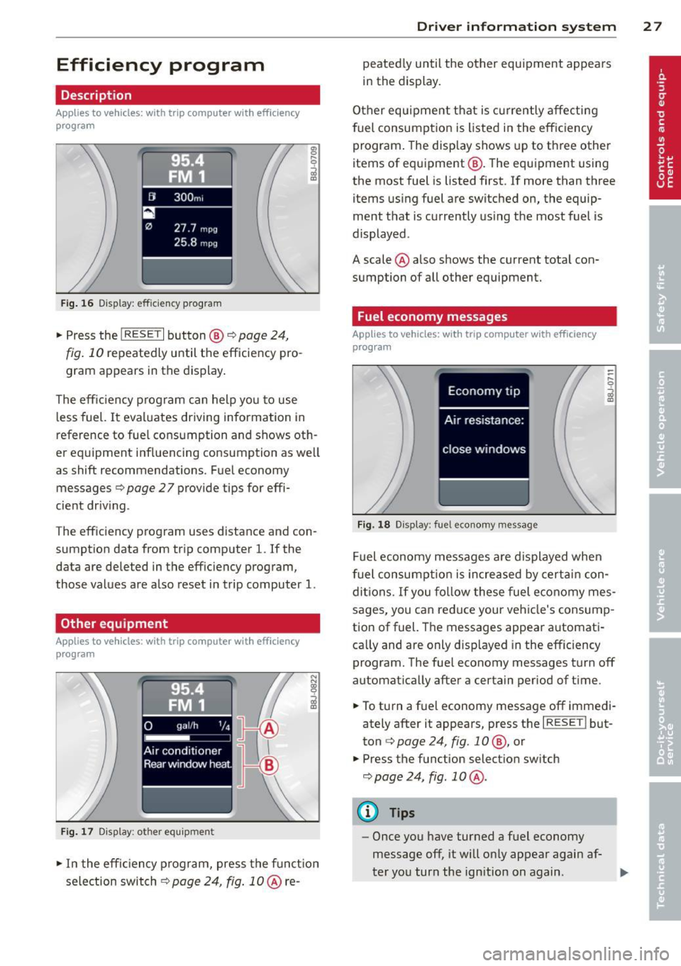
Description
Applies to vehicles: with trip computer with efficiency
program
• 95
!'4 . FM 1
[JI 300 m,
27.7 m pg
25.8 mpg
Fig. 16 Di.splay : effic ie ncy program
.,. Press the I RESET I button@¢ page 24,
fig. 10 repeatedly until the efficiency pro
gram appears in the display .
The eff ic iency p rogram can help yo u to use
l ess fuel.
It eva luates driving information in
reference to fue l cons umption and shows oth
er equipment influencing consumption as we ll
as shift recommendations. F ue l economy
messages ¢
page 27 provide tips for effi
cient dr iv ing .
T he eff iciency program uses distance and con
sumpt ion data from tr ip comp uter
l. If the
data are deleted in the eff iciency program,
those values are a lso reset in trip computer
l.
Other equipment
App lies to vehicles: with trip computer w it h eff ic iency
program
F ig. 1 7 Dis p lay: ot her equ ip m ent
.. In the effic iency program, press the f unct io n
selection switch¢
page 24, fig. 10 @ re-
Dr iver in formation system 2 7
peated ly until the other equipment appea rs
i n the display.
Other equipment t hat is currently affecti ng
fuel consumption is listed in the eff iciency
program . The display shows up to th ree other
items of equ ipment @. The equ ipment us ing
the most fuel is listed first. If more than three items us ing fuel are switched on, the equip
ment that is currently us ing the most fuel is
displayed .
A scale @ also shows the current tota l con
sumption of all other equipment.
Fuel economy messages
App lies to vehicles: with trip computer with efficiency
program
Fi g. 18 Disp lay: fu el e cono my message
Fuel economy messages a re displayed when
fuel consu mpti on is increased by cert ain con
d iti ons.
If you fo llow these fuel e conomy mes
sages, you can reduce your veh icle's consump
tion of fuel. The messages appea r automati
ca lly and are only d isp layed in the efficiency
program. The fue l economy messages t urn off
automat ica lly after a certain period of t ime .
.. To turn a f uel economy message off immed i
ately after it appears, press the
I RESE TI but
ton ¢
page 24, fig . 1 0 @, or
.. Press the f unction select ion sw itch
¢ page 24, fig . 10 @.
(D Tips
-Once you have turned a fuel economy
message off, it will on ly appear agai n af-
t er yo u turn the ign ition on again .
IJJ,
Page 79 of 244
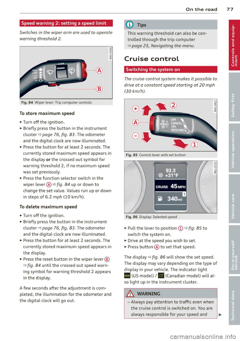
Speed warning 2: setting a speed limit
Switches in the wiper arm are used to operate warning threshold
2 .
'----I ®
Fig. 84 W iper lever: Trip computer controls
To store maximum speed
.. Turn off the ignit ion .
.. Briefly press the button in the instrument
cluster¢
page 76, fig. 83. The odometer
and the digital clock are now illuminated .
.. Press the button for at least 2 seconds. The
currently stored maximum speed appears in
the display
or the crossed out symbol for
warning threshold 2, if no maximum speed
was set previously .
.. Press the function selector switch in the
wiper lever@¢
fig. 84 up or down to
change the set value. Values run up or down
i n steps of 6.2 mph (10 km/h).
To delete maximum speed
.. Turn off the ignition.
.. Briefly press the button in the instrument
cluster ¢
page 76, fig. 83. The odometer
and the digital clock are now illuminated.
.. Press the button for at least 2 seconds. The
currently stored maximum speed appears in
the display.
.. Press the reset button in the wiper lever®
¢
fig . 84 until the crossed out speed warn
ing symbol for warning threshold 2 appears
in the d isplay.
A few seconds after the adjustment is com pleted, the illumination for the odometer and
the digital clock will go out.
On the road 77
@ Tips
This warning threshold can a lso be con
trolled through the trip computer
¢ page 25, Navigating the menu.
Cruise control
Switching the system on
The cruise control system makes it possible to
drive at a constant speed starting at
20 mph
(30kmlh).
®-
Fig. 85 Co ntro l leve r w ith set b utto n
Fig. 86 Display : Se lected speed
.. Pull the lever to position @¢ fig. 85 to
switch the system on .
.. Dr ive at the speed you w ish to set .
.. Press button @ to set that speed.
The display ¢
fig. 86 will show the set speed .
The display may vary depending on the type of
display in your vehicle. The indicator light
II (US model) /. (Canadian model) will al
so light up in the instrument cluster .
A WARNING
-Always pay attention to traffic even when
the cruise control is switched on. You are
always responsible for your speed and
Page 240 of 244
238 Index
Tire pressure monitoring system ...... . 198 Trip computer ..... ............. ..... 23
Loss of air pressure ........ ... .... .
199 Single-trip memory ................. 23
M alfunct ion . ............. ... .... .
199 Tota l-trip memory .................. 23
Resetting tire pressures . . . . . . . .
200, 201 Trip odometer . .. .. ............. .. .. . 12
Tire repair kit ............. .. .. .... . 205 What does it mean when dEF appears in
Tires .. .. .... .......... ........ ... .
180 the trip odometer display? ....... ... . 12
Replacing .. ................ ... ... 191 Trunk lid ...... ... .. .............. .. 37
run-flat .. ... ............ .. .. .. .. .
201 Trunk escape handle ........... .. .. 204
Service life .............. .. .. .... . 190 Turn signals ... .. .. ............. .. .. . 50
speed rat ing letter code . .. .. .. .. .. . 192 Warning/indicator lights ........ .. .. . 21
Tire manufacturing date ......... ... 192
Tire specifications ............ .... . 192 U
Tread depth .............. ... .... . 190
Uniform tire quality grading .. .. ..... 194
Winter tire s ............... .. .... . 195
Tires/Whee ls
Low aspect ratio tires ....... ... .. .. .
197
Tire mobility system ....... .... ... . 205
Tire pressure monitoring system .... . 198
Tire repair kit ............ .. .. .. .. . 205
Tir es and vehicle load limits ... ... .... . 188
Tires and wheels
Check ing tire pressure ..............
186
Cold tire inflation pressure ..... .. .. . 184
Dimensions ............ .. .. .. .. .. .
191
General notes .............. .. .... . 180
Glossary of tire and loading termino lo-
gy . ... .... ................ ..... .
181
New tires and wheels ............... 191
Replacing ............... .. .. .... . 192
Snow chains ............... .. .... . 196
Tires and vehicle load limits .. .. .. ... 188
Wheel bolts ... ... .... ..... .. .. .. .
197
W inter t ires ... .......... .. .. .. .. . 195
Tire serv ice life .. .......... .. .. .... . 190
Tool kit ..... ................ ..... . 204
Towing
Front eyelet .................. ....
219
Rear eyelet ... ......... .. .. .. .. .. . 220
Tow truck procedures ............... 218
TPMS
Tire pressure monitoring system .. ... 199
Trailer towing . . . . . . . . . . . . . . . . . . . . . . 153
Transmission
S tron ic transmission ................ 81
Transport Canada . . . . . . . . . . . . . . . . . . . .
98
Tread Wear Indicator (TWI) ... ... .. .. . 190
Unfastening safety belts
Unidirectional tires .... .......... .. . .
Uniform tire quality grading ......... .
Univ ersal Radio- Frequency Remote Con-105
180
194
trol (HomeLink) . .. ............. .. .. . 88
Unlocking
Power locking switch ......... .. .. .. .
36
Rear lid/trunk lid ................. .. 37
Remote control key .................
35
Using the key ...................... 36
V
Vanity mirror . . . . . . . . . . . . . . . . . . . . . . . . 54
Vehicle
care/cleaning .. .. ... .......... ....
154
Vehicle electrical system ......... .... . 16
Vehicle Identification Number (V IN) . ... 222
Vehicle jack ... .. .. ....... ...... .. .. 209
Vehicle literature ..................... 5
Vehicle shut-down .............. .. ..
151
Vehicle tool kit .. .. ....... ...... .. .. 204
Ventilation ..... .. ............. ..... 67
Vinyl
Cleaning .. ...... ............. ....
157
w
Warning/ind icator lights . . . . . . . . . . 10, 12
Airbag system . .. ............. .. .. . 15
Anti-lock brake system (ABS) . . . . . . . . . 18
Brake system . . . . . . . . . . . . . . . . . . . . . .
14
Convertible top . . . . . . . . . . . . . . . . . . . . 17
Cruise contro l . . . . . . . . . . . . . . . . . . . . . . 21
Electronic power control .......... .. . 19