check engine AUDI TT ROADSTER 2017 Owner's Manual
[x] Cancel search | Manufacturer: AUDI, Model Year: 2017, Model line: TT ROADSTER, Model: AUDI TT ROADSTER 2017Pages: 314, PDF Size: 76.54 MB
Page 243 of 314
co
co
.... N
" N .... 0
" "' c:o
Cooling system
Coolant
The engine cooling system is filled with a mixture
of pur ified water and coolant additive at the fac
tory. This coo lant must not be not changed.
The coolant level is monitored through the. in
dicator light
¢page 12. However , we do recom
mend occasionally check ing the coo lant level
manually.
If you must add coolant, use a mixture of water
and coolant addit ive. Mixing the coolant additive
with distilled water is recommended.
Coolant additive
The coolant additive is made of anti-freez ing and
corros ion protection agents. Only use the follow
ing coolant addit ives . These additives may be
mixed with each other.
Coolant additive Specification
G13 TL 774
J
G12++ TL 774 G
The amount of coo lant add itive that needs to be
mixed with water depends on the climate where
the vehicle will be operated. If the coolant addi tive percentage is too low, the coolant can freeze
and damage the engine.
Coolant addi- Freeze protec-
tive tion
Warm regions min. 40%, m in. -13 °F
max. 45% (-25 °C)
Cold regions min. 50%, max
. -40 °F
max. 55% (-40 °C)
(D Note
- Before the start of winter, have your author
ized Audi dealer or authorized Audi Service
Facility check if the coolant additive in your
vehicle matches the percentage appropriate
for the climate . Th is is especially important
when driving in colder climates.
- If the appropriate coolant additive is not
available in an emergency, do not add any
other additive . You could damage the en-
Checking and Filling
gine. If this happens, only use water and re
store the correct mixture ratio with the
specified coolant add it ive as soon as possi
ble.
- Only refill with new coolant .
- Radiator sealant must not be mixed with
the coolant.
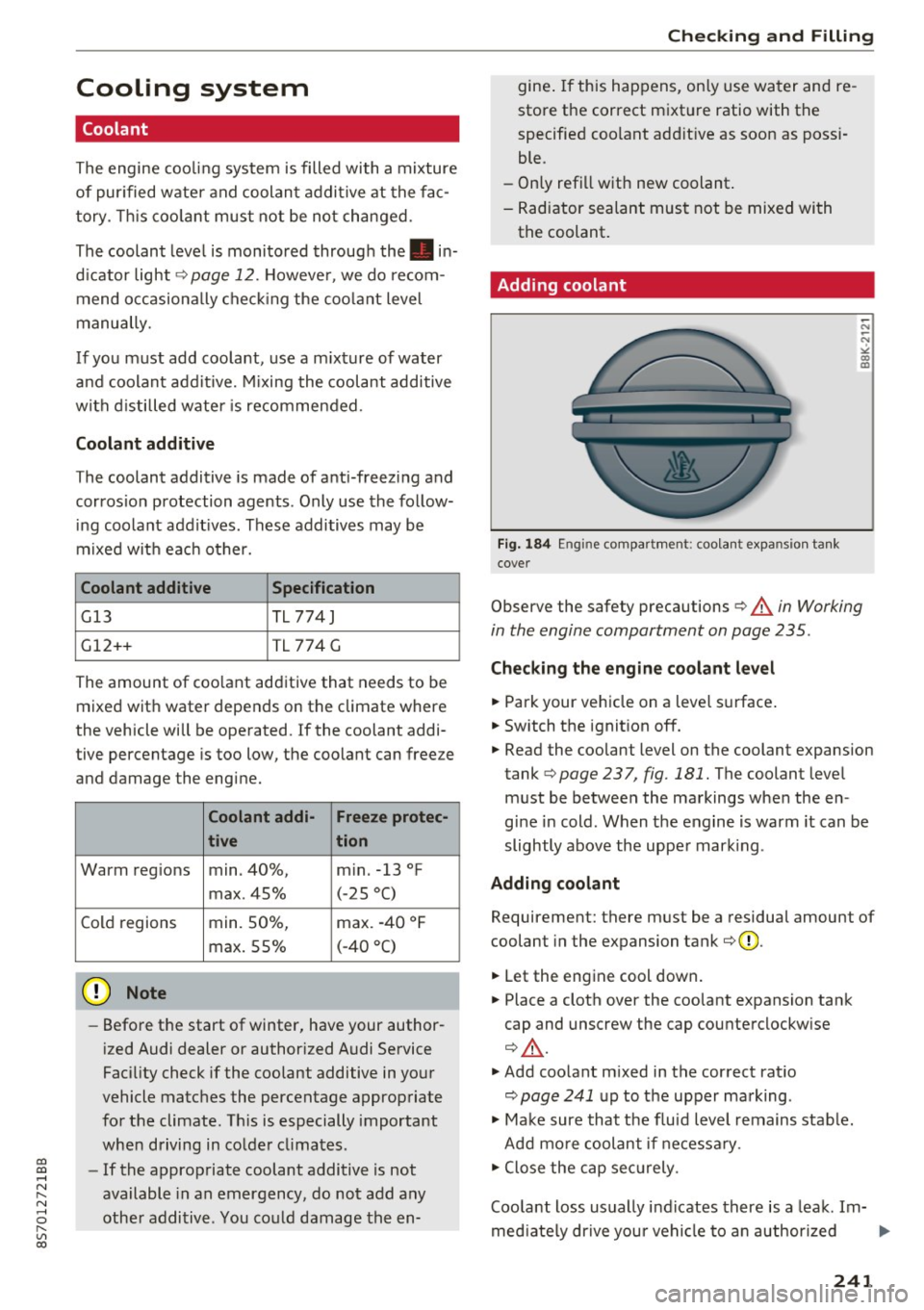
Adding coolant
Fig. 184 Engine compartment: coolant expansio n ta nk
cover
-N
-N
"" CD co
Observe the safety precautions ¢ A in Working
in the engine comportment on page 235.
Checking the engine coolant level
.,. Park your vehicle on a leve l surface .
.,. Switch the ignition off.
.,. Read the coolant level on the coolant expansion
tank
¢ page 237, fig . 181. The coolant level
must be between the markings when the en
gine in cold . When the engine is warm it can be
slightly above the upper mark ing .
Adding coolant Requirement: there must be a residual amount of
coolant in the expansion tank
¢ (D .
.,. Let the engine cool down.
.,. Place a cloth over the coolant expansion tank
cap and unscrew the cap counterclockw ise
Q .&, .
.,. Add coolant m ixed in the correct rat io
¢ page 241 up to the upper marking .
.,. Make sure that the fluid level remains stable.
Add more coolant if necessa ry .
.,. Close the cap securely .
Coo lant loss usually indicates there is a leak. Im-
mediately drive your vehicle to an author ized .,..
241
Page 244 of 314
Checking and Filling
Audi dealer or authorized Audi Service Facility
and have the cooling system inspected. If the
cooling system is not leaking, a loss can come
from the coolant boiling through overheating
and being pushed out of the cooling system.
A WARNING
The cooling system is pressurized and can be
come very hot. To reduce the r isk of burns
from hot coolant:
- Do not open the coolant expansion tank cap when the eng ine is hot. This increases the
risk of burns.
- Stop the engine and allow it to cool.
- Protect your face, hands and arms from es-
caping coolant and steam by covering the
coolant tank cap with a large, thick cloth.
- Turn the coolant tank cap counterclockwise
slowly and keep light pressure o n the cap.
- To reduce the risk of burns, do not allow any
antifreeze or coolant to drip onto the ex haust system or hot eng ine components .
T he ethylene glycol in eng ine coolant can
catch fire under certa in circumstances.
- The coo lant add itive and the coolant can be
dange rous to your health. For this reason,
keep the coolan t in the origina l container
and away from children. There is a risk of
poisoning.
- When working in the engine compartmen t,
remember that the radiator fan can switch
on even if the ignition is switched off, which
increases the risk of inj ury.
(D Note
Do not add coolant if the exp ansion tank is
empty . Air could enter the cooling system and
damage the engine . If this is the case, do not
continue driving. See an authorized Audi deal
er or authorized Audi Service Facility for assis
tance.
242
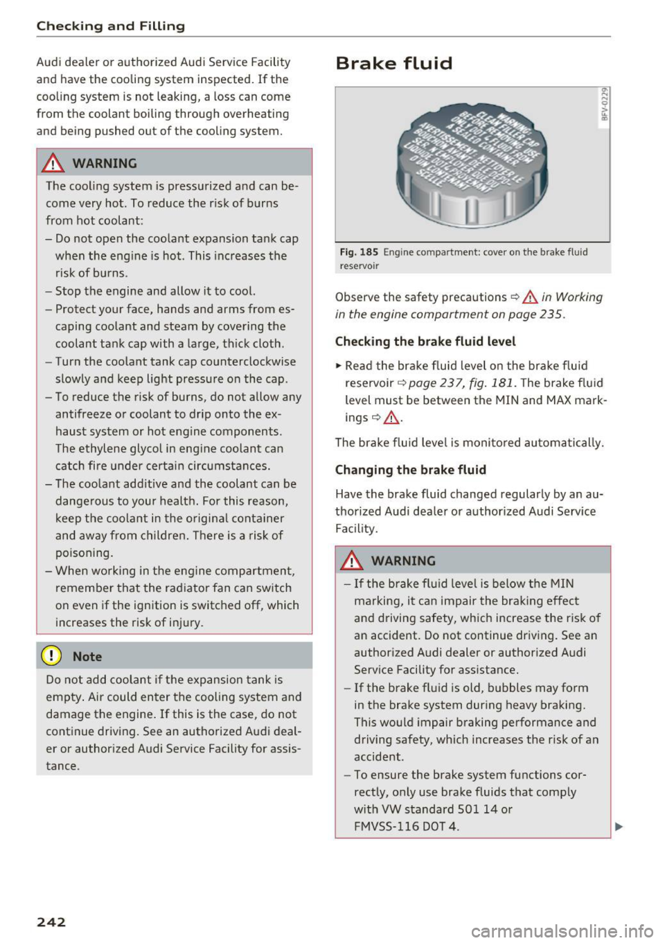
Brake fluid
Fig. 1 85 Eng ine compa rtment: cover o n the brake fluid
reservo ir
Observe the safety precautions ¢ A in Working
in the engine compartment on page 235.
Check ing the brake fluid level
... Read the bra ke fluid level o n the bra ke flu id
reservoir
¢ page 237, fig . 181. The brake f luid
level must be between the MIN and MAX mark
ings ¢&_ .
The brake f lu id leve l is monito red au toma tically.
Changing the brake fluid
Have the brake fluid changed regularly by an au
thorized Audi dea ler or authorized Audi Service
Fac ility.
A WARNING
- I f the brake fl uid leve l is below the MIN
marking, it can impair the bra king effec t
and driving safety, which increase the risk o f
an accident . Do not continue driv ing. See a n
author ized Audi dealer or authorized A udi
Serv ice Facility for assistance.
- If the brake fl uid is old, b ubbles may form
in the brake system during heavy braking.
This would impair braking performance and
driving safety, which increases the r isk of an
accident.
- To ensure the brake system functions cor
rectly, only use brake fluids that comply
w it h VW standard SO l 14 or
FMVSS- 116 DO T 4.
Page 245 of 314
co
co
.... N
" N .... 0
" "' c:o
CD Note
-If the brake fluid level is above the MAX
mark ing, brake fluid may leak out over the
edge of the reservoir and result in damage
to the vehicle.
- Do not get any brake f luid on the vehicle
paint, because it will corrode the paint.
Battery
General warnings about batteries
All of the batteries in yo ur vehicle are practically
ma intenance-free and are checked during a ve hi
cle inspection . Because of the complex power
supp ly, all work on batter ies such as d isconnect
ing, replacing, etc. should
o nly be performed by
an author ized Audi dealer or authorized Audi
Service Facility
c> & -
The term "vehicle battery" refers to the 12 Vo lt
battery in your veh icle.
Detailed wa rning s for the vehicle batte ry:
®
Wear eye p rotection.
A
Battery acid is hig hly co rrosive. Wea r pro-
tective g loves and eye pro tect ion.
@
Fire, sparks, open flame and smok ing are
forb idden.
~
A highly exp losive mixtu re of gases can
form when charging batteries.
®
Keep childre n away from battery acid and
batteries.
A WARNING
All work on the battery or electrical system in
your vehicle can result in injuries, chemical
burns, accidents or burns. Because of this, a ll
work m ust be perfo rmed
only by an author
ized Aud i deale r or authorized Audi Serv ice
Facility.
A WARNING
California Proposition 65 Warn ing:
- Battery posts, terminals and re lated acces
sories contain lead and lead compounds,
Ch eck ing and Filling
chemicals known to the State of California
to cause cancer and reproductive problems.
Wash hands after handling.
CD Note
Protect the vehicle battery against freezing if
the veh icle wi ll be parked for long periods of
time so that it is not destroyed by "freezing"
c> page244.
Vehicle battery
The term "vehicle battery" refers to the 12 Volt
battery in your vehicle.
Not running the vehicl e for long periods of
time
If you do not drive your vehicle for severa l days or
weeks, electrical equ ipment is gradua lly scaled
back or sw itched off. Th is reduces energy use and
ensures the vehicle will be ab le to start after long
per iods of time
c> page 93 . Some convenience
func tions, such as i nterio r lighting o r power seat
adjus tme nt, may no t be ava ilab le unde r certain
cir cumstances . These convenience func tions will
be available again once you switch the ignit ion on
and start the engine.
E ven when elec trical equipment is switched off,
the eq uipment can sti ll dr ain the vehicle ba ttery
i f the veh icle is not dr iven for long periods of
t ime . Deep dra ining resu lts in a chemica l reaction
t h at destroys the inside of the vehicle batte ry.
The veh icle battery must be charged every month
to red uce the risk of this happening
c> page 244.
Contact an authorized Aud i dea ler or authorized
Audi Service Facility for more information .
Winter operat ion
Co ld weather places higher demands on the vehi
cle battery. Th is res ults in reduced starting ab ili
ty. Have the vehicle battery checked by an au
thorized Aud i dea ler or authorized Audi Service
Facility before the cold time of year .
243
Page 246 of 314
Checking and Filling
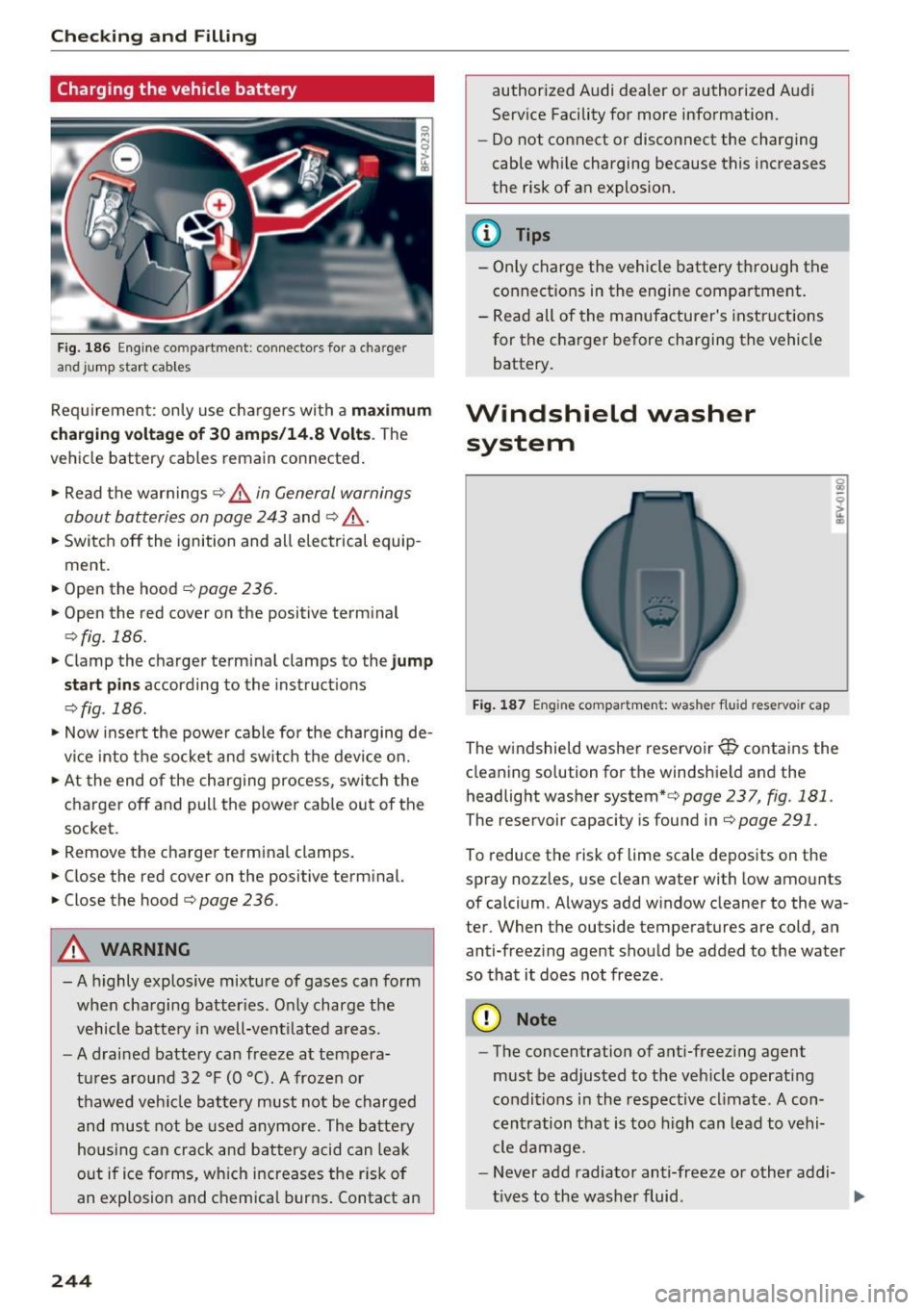
Charging the vehicle battery
Fig. 186 Engine co mpa rtment : connec tors for a c harger
and jump start cab le s
Req uirement: only use chargers with a m aximum
c hargi ng vo lta ge of 30 amp s/14.8 Volt s.
The
vehicle battery cables remain connected .
.,. Read the warnings
c> .&. in General warnings
about batteries on page 243
and c> ,&. .
.,. Switch off the ignition and all electrical equip
ment .
.,. Open the hood ¢
page 236 .
.,. Open the red cover on the positive terminal
c> fig. 186 .
.,. Clamp the charger terminal clamps to the jump
s ta rt pin s
according to the instruct ions
c> fig . 186 .
.,. Now inse rt the powe r cable for the charging de
v ice into the socket and sw itch the device on.
.,. At the end of the charging process, switch the
charger off and pull the powe r cab le out of the
socket .
.,. Remove the charger terminal clamps.
.,. Close the red cover on the positive term inal.
.,. Close the hood¢
page 236.
A WARNING
- A highly explosive mixture of gases can form
when cha rging batter ies. Only charge the
vehicle batte ry in well-vent ilated areas.
- A drai ned battery can freeze at tempera
t ur es a round 32 °F (0 °C) . A frozen or
thawed veh icle battery must not be charged
and must not be used anymore. The batte ry
housing can crac k and battery acid can leak
o ut if ice fo rms, wh ich increases the risk of
an explosion and chemical burns . Contact an
244
author ized Audi dealer or authorized A udi
Service Facility for more information.
- Do not connect or disconnect the charging
cable whi le charging because this increases
the risk of an explos ion.
@ Tips
- Only charge the vehicle battery t hrough the
connect ions in the engine compartme nt.
- Read all of the manufacturer's instructions
for the charger before charging the vehicle
battery.
Windshield washer system
Fi g. 18 7 Engine compar tm ent: washer flui d res ervoir cap
The windshield washer reservoir~ contains the
cleaning so lu ti on for th e windshield and the
headlight washer system*c>
page 237 , fig. 181 .
The reservoir capaci ty is found in c> page 291.
To reduce the risk of lime scale depos its on the
spray nozzles, us e clean water with low amo unts
of calcium . Always add w indow cleaner to the wa
ter . When the ou tside temperatures a re cold , an
anti-freez ing agent should be added to the water
so that it does not freeze .
(D Note
-The concentration of ant i-freez ing agent
must be adjusted to the veh icle operat ing
conditions i n the respective cl imate. A con
cen tration that is too high can lead to vehi-
cle damage.
- Never add radiato r anti-freeze or other addi-
t ives to the washer fluid . ...,
Page 247 of 314
co
co
.... N
" N .... 0
" "' c:o
-Do not use a glass cleaner that contains
paint solvents, because this could damage
the pa int.
Service interval display
The service interval display detects when your ve
hicle is due for service.
The service interval display works in two stages:
- Inspection or oil change reminder: after a cer-
tain distance driven, a message appears in the
Infotainment system display each time the ig
nition is switched on or off. The remaining dis
tance or time is displayed briefly.
- Inspection or oil change due: if your vehicle
has reached an inspection or oil change interval
or both intervals at the same time, the mes
sage
Inspection due! or Oil change due! or Oil
change and inspection duel
appears briefly af
ter switching the ignition on/off .
Checking service intervals
You can check the remaining distance or time un
til the next oil change or next inspection. Select
in the Infotainment system: the !MENU ! button>
Vehicle > left control button > Service & checks >
Service intervals .
(D Note
-Following the service intervals is critical to
maintain ing the service life and value of
your vehicle, especially the engine. Even if
the mileage on the vehicle is low, do not ex
ceed the time for the next service.
- Calcu lating the time to the next oil change
i s interrupted when the vehicle battery is
disconnected~
page 271.
Checking and Filling
245
Page 279 of 314
CD
CD
.... N
" N .... 0 r--. V, co
-To reduce the risk of injury, support the ve
hicle securely with suitable stands if work is
to be performed underneath the vehicle.
- To help prevent injury to yourself and your
passengers:
- Do not raise the vehicle until you are sure
the jack is securely engaged .
- Passengers must not remain in the vehicle
when it is jacked up.
- Make sure that passengers wait in a safe
place away from the vehicle and well away
from the road and traffic.
- Make sure jack position is correct, adjust
as necessary and then continue to raise
the jack.
- If work has to be done under the vehicle,
ensure that it is safely supported on suita
ble stands -risk of injury!
- Never start the engine when the vehicle is
on the jack -risk of accident!
(D Note
Do not lift the vehicle by the sill . Position the
vehicle jack* only at the designated mounting points on the side sill. Otherwise, your vehicle
will be damaged.
Removing and mounting a wheel
Fig. 202 Wheel : internal hex socket to turn the wheel
bolts
Emergency assistance
Fig. 203 W hee l: alignment pin in the top ho le
Removing a wheel
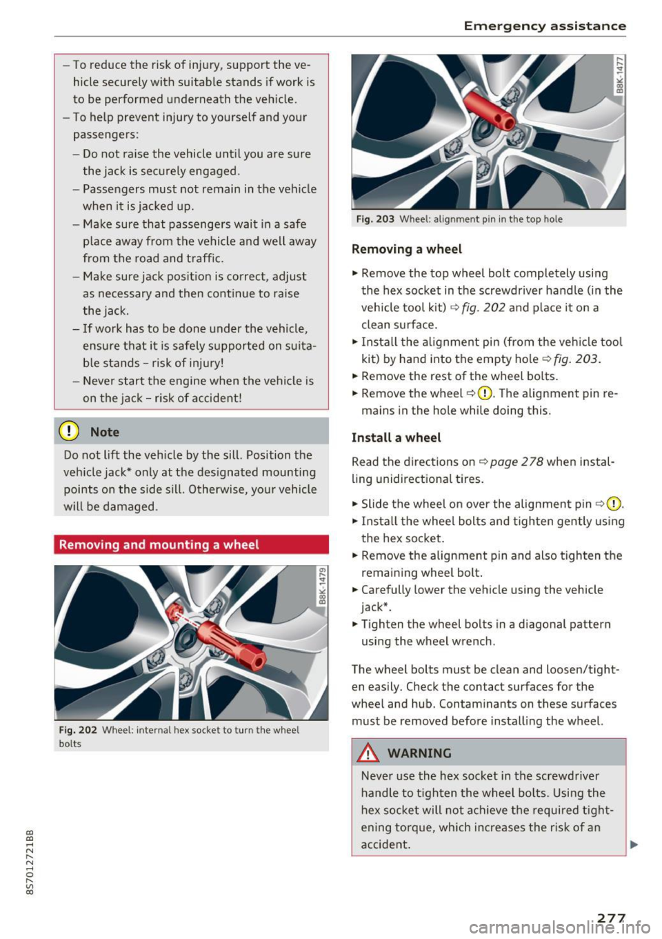
.,. Remove the top wheel bolt completely using
the hex socket in the screwdriver handle (in the
vehicle tool kit)
c::> fig. 202 and place it on a
clean surface.
.,. Install the alignment pin (from the vehicle tool
kit) by hand into the empty hole
c::>fig. 203 .
.,. Remove the rest of the wheel bolts.
.,. Remove the wheel
c::>0. The alignment pin re-
mains in the hole while doing this.
Install a wheel
Read the directions on c::> page 2 78 when instal
ling unidirectional tires.
.,. Slide the wheel on over the alignment pin
c::>(D.
.,. Install the wheel bolts and tighten gently using
the hex socket.
.,. Remove the alignment pin and also tighten the
remai ning wheel bolt .
.,. Carefully lower the vehicle using the vehicle
jack* .
.,. Tighten the wheel bolts in a diagonal pattern
using the wheel wrench .
The wheel bolts must be clean and loosen/tight
en easily. Check the contact surfaces for the
wheel and hub . Contaminants on these surfaces
must be removed before installing the wheel.
A WARNING
-
Never use the hex socket in the screwdriver
handle to tighten the wheel bolts . Using the
hex socket will not achieve the required tight
ening torque, which increases the risk of an
accident .
277
Page 283 of 314
CD
CD
.... N
" N ...... 0 r--. V, co
Fuses and bulbs
Electrical fuses
Replacing fuses
A fuse that has blown will have metal strips tha t
have burned through .
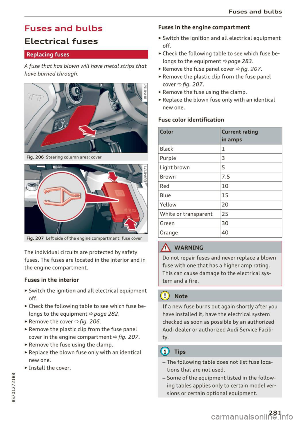
Fig. 206 Steer ing colu mn area : cove r
Fig. 207 Left side of the engin e com partment : fus e cover
The individual circuits are protected by safety
fuses. The fuses are located in the interior and in
the engine compartment.
Fuses in the interior
"S witch the ignition and all electrical equipment
off .
"C heck the following table to see which fuse be
longs to the equipment ¢
page 282.
" Remove the cover ¢ fig. 206.
"Remove the plastic clip from the fuse panel
cover in the engine compartment¢
fig. 207.
"Remove the fuse using the clamp.
" Replace the blown fuse only with an identical
new one .
"Install the cover .
Fuses and bulbs
Fuses in the engine compartment
"S witch the ignition and all electrical equipment
off .
.. Check the following table to see which fuse be
longs to the equipment¢
page 283.
.. Remove the fuse panel cover c::> fig. 207.
" Remove the plastic clip from the fuse panel
cover ¢
fig. 207.
" Remove the fuse using the clamp .
.. Rep lace the blown fuse only with an identical
new one.
Fuse color identification
Color Current rating
in amps
Black
1
Purpl e 3
Light brown 5
Brown 7.5
Red 10
Blue 15
Yellow 20
White or transparent 25
Green 30
Orange 40
&, WARNING
-
Do not repair fuses and never replace a blown
fuse with one that has a higher amp rating.
This can cause damage to the electrica l sys
tem and a fire .
(D Note
If a new fuse burns out again shortly after you
have instal led it, have the electrical system
checked as soon as possible by an authorized
Audi dealer or authorized Audi Service Facili
ty.
© Tips
- Th e following table does not list fuse loca
tions that are not used.
- Some of the equipment listed in the follow
ing tables applies only to certain model ver
sions or certain optional equipment.
281
Page 286 of 314
Emergency situations
Emergency situations
General
This chapter is intended for trained emergency crews and working personnel who have the nec
essary tools and equipment to perform these
operations.
Starting by pushing or
towing
CD Note
Vehicles with an automatic transmission can
not be started by pushing or towing.
Starting with jumper
cables
If necessary, the engine con be started by con
necting it to the battery of another vehicle .
If the engine should fail to start because of a dis
charged or weak battery, the battery can be con
nected to the battery of
another vehicle, using a
pair of jumper cables to start the engine.
Jumper cables
Use only jumper cables of sufficiently large cross
section
to carry the starter current safely. Refer
to the manufacturer's specifications.
Use only jumper cables with
insulated terminal
clamps which are distinctly marked :
plus(+) cable in most cases colored red
minus(-) cable
in most cases colored black .
A WARNING
Batteries contain electricity, acid, and gas.
Any of these can cause very serious or fatal in
jury. Follow the instructions below for safe hand Ling of your vehicle's battery .
-Always shield your eyes and avoid leaning
over the battery whenever possible.
-A discharged battery can freeze at tempera
tures just below 32 °F (0 °C). Before con
necting a jumper cable, you must thaw the
284
frozen battery completely, otherwise it could explode .
- Do not allow battery acid to contact eyes or
skin. Flush any contacted area with water immediately.
- Improper use of a booster battery to start a
vehicle may cause an explosion.
- Vehicle batteries generate explosive gases.
Keep sparks, flame and lighted cigarettes
away from batteries.
- Do not try to jump start any vehicle with a
low acid level in the battery .
- The voltage of the booster battery must also
have a 12-volt rating. The capacity (Ah) of
the booster battery should not be lower
than that of the discharged battery. Use of
batteries of different voltage or substantial
ly different "Ah" rating may cause an explo
sion and personal injury .
- Never charge a frozen battery. Gas trapped in the ice may cause an explosion .
- Never charge or use a battery that has been
frozen . The battery case may have be weak
ened .
- Use of batteries of different voltage or sub stantially different capacity (Ah) rating may
cause an explosion and injury. The capacity
(Ah) of the booster battery should not be
lower than that of the discharged battery.
- Before you check anything in the engine
compartment, always read and heed all
WARNINGS
~page 235.
CD Note
-Applying a higher voltage booster battery
will cause expensive damage to sensitive
electronic components, such as control
units, relays, radio, etc.
- There must be no electrical contact between
the vehicles as otherwise current could al
ready start to flow as soon as the positive
(+) terminals are connected.
@ Tips
The discharged battery must be properly con-
nected to the vehicle's electrical system. .,..
Page 287 of 314
CD
CD
.... N
" N ...... 0
" V, co
When jump starting or charging the battery,
never connect the negative ground cable to
the battery negative post because the battery
manager system must be able to detect the
battery's state of charge. Always connect the
negative ground cable to the negat ive ground
post of the battery manager control unit .
Use of jumper cables
Make sure to connect the jumper cable clamps in
exactly the order described below!
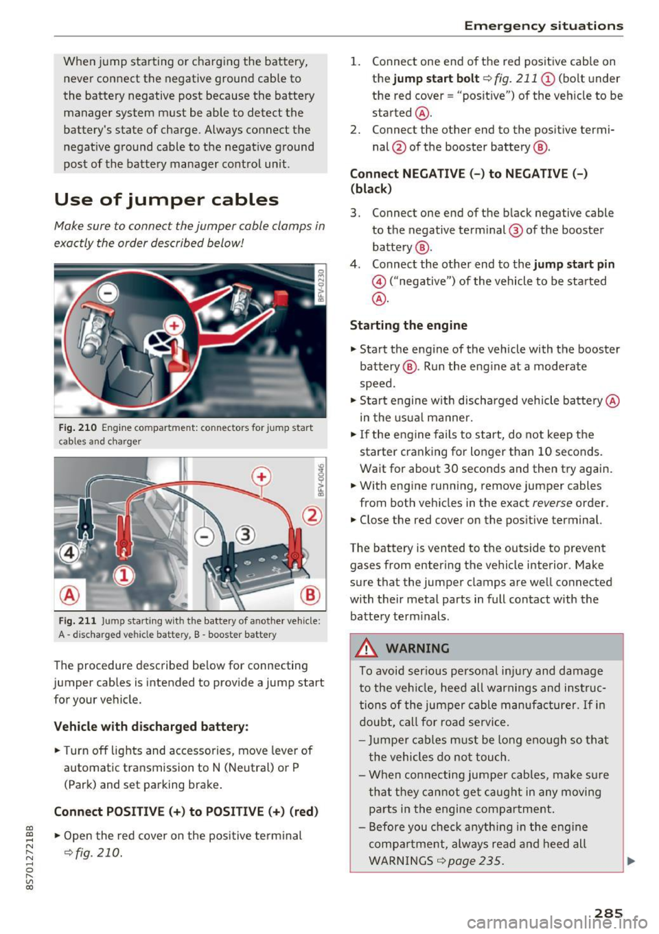
Fig. 210 Engine compartment: connectors for jump start
cables and c harger
Fig. 211 Jump starting w ith the battery of another vehicle :
A -discharged vehicle battery, B -booster battery
The proc edure desc ribed below for connecting
jumper cables is intended to provide a jump start
for your vehicle.
Vehicle with discharged battery:
.. Turn off lights and accessories, move lever of
automatic transmission to N (Neutral) or P
(Park) and set parking brake .
Connect POSITIVE(+) to POSITIVE(+) (red)
.,. Open the red cover on the positive terminal
~fig. 210.
Emergency situations
1. Connect one end of the red positive cab le on
the
jump start bolt~ fig. 211 (D (bolt und er
the red cover= "posit ive") of the veh icle to be
sta rted @.
2. Connect the other end to the posit ive termi-
nal @of the booster battery @.
Connect NEGATIVE (-) to NEGATIVE (- )
(black)
3. Connect one end of the black negative cable
to the negative terminal @ of the booster
battery @.
4. Connect the other end to the
jump start pin
@ ("negative") of the vehicle to be started
@.
Starting the engine
.. Start the engine of the vehicle with the booster
battery @. Run the eng ine at a moderate
speed .
.,. Start engine w ith discharged vehicle battery @
in the usual manner.
.,. If the engine fails to start, do not keep the
starter cranking for longer than 10 seconds.
Wait for about 30 seconds and then try again .
.. With engine running, remove jumper cables
from both vehicles in the exact
reverse order .
.. Close the red cover on the positive terminal.
The battery is vented to the outside to prevent
gases from entering the vehicle interior . Make
sure that the jumper clamps are well connected
with their metal parts in full contact with the battery term inals .
A WARNING
To avoid ser ious personal injury and damage
to the vehicle, heed all warnings and instruc
tions of the jumper cable manufacturer.
If in
doubt, call for road service.
- Jumpe r cables must be long enough so that
the vehicles do not touch .
- When connecting jumper cables, make sur e
that they cannot get caug ht in any moving
parts in the engine compartment.
- Before you check anything in the engine
compa rtment, always read and heed all
WARNINGS ~
page 235 .
285
Page 288 of 314
Emergency situations
(D Note
Improper hook -up of ju mper cables can r uin
the generato r.
- Always con nect P OSITIVE( +) to POS ITI VE
( + ), and NEG ATI VE( -) to NEGATIVE( -)
ground post of t he battery manage r contro l
u nit .
- Check that a ll sc rew p lugs on the battery
cells are sc rewed in firmly . If not, t ighten
plugs p rior to connect ing clamp o n negat ive
b attery t erminal.
- Please note t hat the procedure fo r con nect
i ng a jumper cable as desc rib ed above ap
plies specifica lly to the case of yo ur vehicle
being jum p starte d. When you a re giv ing a
ju mp sta rt to anothe r vehicle, do
not con
n e ct t he neg ative( -) ca b le to the neg ative
(- ) termin al o n t he dis ch arged battery @
¢
fig . 21 1. In ste ad, securely connec t the
negative (-) cab le to either a so lid metal
compo nent that is f irm ly bolted to the e n
gine block o r to the engine bloc k itself. If
the battery that is bei ng cha rged does not
vent to the outside, escap ing battery gas
could ignite an d exp lode!
Towing with a tow truck
General hints
Your Audi requires special handling for towing.
The fo llow ing informa tion is to be used by com
mercial tow truck operators who know how to op
era te the ir equipmen t sa fe ly .
- Never tow your Audi. Towing will cause dam
age to the engine and transmi ssion.
- Never wrap the safety chains or winch cables
around the brake l ines .
- To prevent unnecessary damage, your Audi
must be transported with a flat bed truck.
- To load the vehicle on to the flat bed , use the
towing loop found in the vehicle tools and at
tach to the front or rear anchorage
¢ page 286 and ¢ page 287.
286
A WARNING
A veh icle being towed is not safe for passe n
ge rs . Neve r allow a nyone to ride in a vehicle
be ing towed, fo r any reason .
Front towing loop
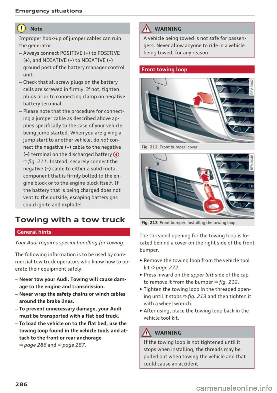
Fig. 212 Fron t bumper : cover
Fi g. 2 13 Fron t bumper : install ing the tow ing loop
The threaded opening for the towing loop is lo
cated behind a cover on the rig ht side of the front
bumper .
.. Remove the towing loop f rom the vehicle too l
kit¢
page 272.
.. Press inward on the
upper left side of the cap
to remove i t from the bumper ¢
fig. 212 .
.,. Tighten the towing loop in the threaded o pen
ing until it s tops ¢
fig. 213 and then tig hten it
w it h a wheel w re nch.
.,. After usi ng, p lace the tow ing loop b ack in the
veh icle tool kit.
A WARNING
If t he t ow ing l oop is not tig htened unt il it
stops when installing, the threads may be pu lled out when towing the vehicle and that
could cause an accident .
-