brake sensor AUDI TT ROADSTER 2017 Owners Manual
[x] Cancel search | Manufacturer: AUDI, Model Year: 2017, Model line: TT ROADSTER, Model: AUDI TT ROADSTER 2017Pages: 314, PDF Size: 76.54 MB
Page 12 of 314
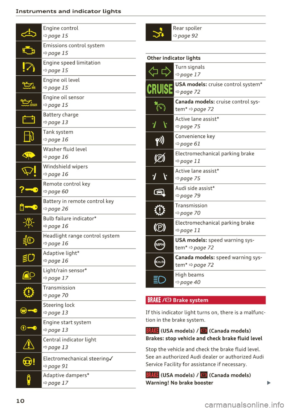
Instruments and indicator lights
Engine control
c::> page 15
Emi ssions control system
c::> page 15
Engine speed limitat io n
c::> page 15
Engine oil level
c::> page 15
Engine oil senso r
c::> page 15
Battery charge
c::> page 13
Tank system
c::> page 16
Washer fluid level
c::> page 16
W indshield wipe rs
c::> page 16
Remote control key
c::> page 60
Battery in remote control key
c::> page 26
Bulb failure ind icator *
c::> page 16
Headlight range control system
c::> page 16
Adaptive light*
c::> page 16
- •
Light/ rain sensor*
c::> page 17
T ransmiss ion
c::> page 70
- Steer ing lock
liliil c::> page 13
10
Engine start system
c::> page 13
Central indicator light
c::> page 13
Electromechan ical steer ing/
c::> page 91
Adapt ive dampers*
c::> page 17
Rear spoiler
c::> page 92
Other indicator lights
- ii
T
ur n signals
c::> page 17
CRUISE
USA model s: cruise control sys tem*
c::> page 72
Canada models :
cruise cont rol sys
t em*
c::> page 72
Active lane ass ist*
c::> page 75
Conven ience key
c::> page 61
E lectromechan ica l park ing brake
c::> page 11
Active lane assist*
c::> page 75
Audi side assist *
c::>page 79
Transm iss io n
c::> page 70
Electromechan ica l par king brake
c::> page 11
USA models: speed warn ing sys
tem*
c::> page 72
C anada models :
speed warning sys
tem*
c::> page 72
- H
igh beams
. c::> page 40
BRAKE / ((J)) Brake sy stem
If this indicato r light turns on, there is a malfunc
tion in the brake system.
1111 (USA mo del s) I. ( Canad a mode ls)
Brake s: stop vehicle and ch eck brake fluid level
Stop the vehicle and check the brake fl uid leve l.
See a n author ized Audi dealer or au thor ized Audi
Se rvice Facil ity for assis tance if necessary .
1111 (USA model s) /. (C anad a mode ls)
Warning! No brake boo ster
Page 63 of 314
CD
CD
.... N
" N ...... 0 r--. V, co
have the malfunction corrected. To start the en
gine, press and hold the
! START ENGINE STOPI
button.
DJ R emot e control key : hold b ack of key
again st the d esignated are a. See owner's man
ual
This message appea rs if the re is no convenie nce
key inside the vehicle or if the system does not
recognize the key . The conven ience key may not
be recognized, for example, if it is cove red by an
object that
disrupts the signal (such as a brief
case), or if the key battery is weak. Electronic de
vices such as cell phones can also interfere with
the signal.
To still be able to start or stop the eng ine, see
c:::> page 61, Starting the engine when there is a
malfunction .
Ill Remote control key : key not recogn ized . Is
the ke y still in th e vehi cle?
The Ill ind icator light turns on and this message
appears if the conve nience key was removed from
the vehicle when the engine was running.
If the
conven ience key is no longer in the vehicle, you
cannot switch the ign ition on or start the engine
once you stop it. You a lso cannot lock the vehicle
from the outside .
Please press brake p edal
This message appears if you do not press the
brake pedal when starting the eng ine.
Please pr ess clut ch p edal
This message appea rs in vehicles w it h manual
transmissions if you do not press the clutch pedal
when sta rting the engine . The engine can on ly be
started when t he clu tch pedal is pressed.
Pl ease select N or P
This message appea rs when starting or stopping
the eng ine if the selector lever is not in the Nor P
position . The engine will not start/stop.
Shift to P , otherw ise vehi cle can roll awa y.
Doors can be lo cked i n P only
This message appears for safety reasons a long
with a warning tone. It appears if the selector
lever for the automatic transmission is not in the
D rivi ng
P position when switch ing the ignit ion off w ith
the
I START ENGINE STOPI b utton. P lace these
l ector lever in the P position. The veh icle cou ld
roll if the lever is not in P. You also cannot lock
the vehicle using the locking sensor on the door handle or using the conven ience key .
Starting the engine when there is a
malfunction
It may not be possible to start the engine under
certain circumstances, for example if th e battery
in the vehicle key is drained, if interference is af
fected the key or if there is a system malfunc
tion.
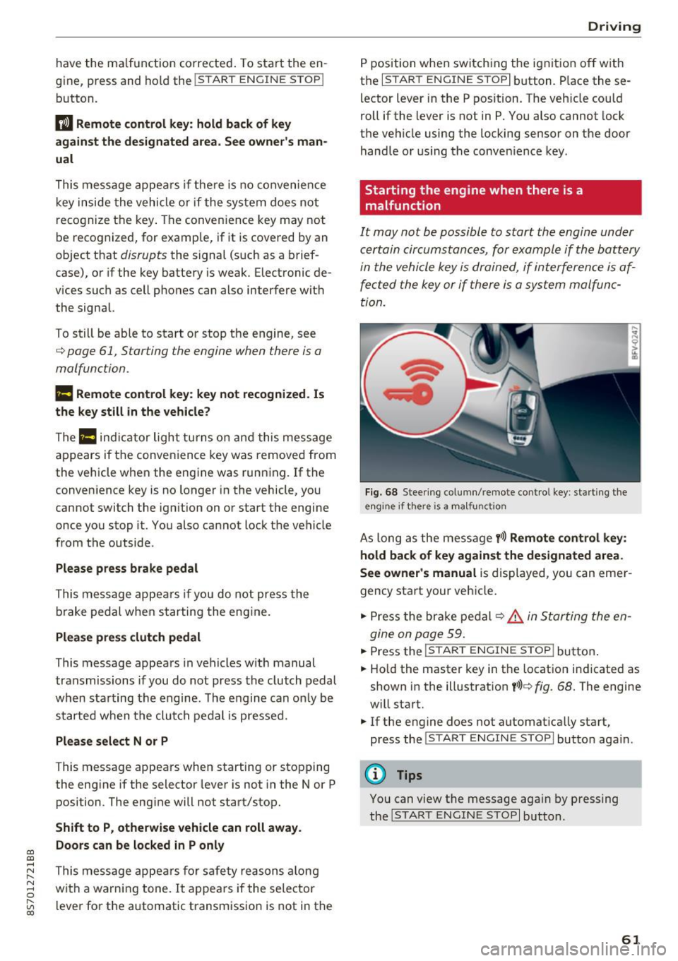
F ig. 68 Steering column/ remote control key: starting the
e n g in e if there is
a m alfunct ion
As long as the message y >l) Remote control key :
hold back of key against the designated are a.
See owner's manual
is displayed, you can emer
gency start your vehicle.
.. Press the brake pedal
c:::> .&. in Starting the en
gine on page 59.
... Press the ~I s=T ~A ~ R~ T~ E_N _G _I _N =E - S~ T= o- P~I button .
.,. Ho ld the master key in the location ind icated as
shown in the illustrat ion
y >l) c:::, fig. 68. The engine
w ill start.
.. If the engine does not automat ica lly start,
press the
! S TART ENGINE STOPI butto n again .
(D Tips
You can view the message aga in by pressing
the
I S TA RT ENGINE S TOP I button.
61
Page 269 of 314
co
co
.... N
" N .... 0
" "' c:o
wash operator to reduce the risk of accidents.
- To reduce the risk of cuts, protect yourself
from sharp metal components when wash
ing the underbody or the inside of the wheel
housings .
- After washing the vehicle, the brak ing effect
may be delayed due to mo isture on the
brake rotors or ice in the w inter . This in
creases the risk of an acc ident. The brakes
must be d ried fi rst w ith a few careful b rake
applications.
(D Note
- If you wash t he vehicle in an automatic car
wash, yo u m ust retract the extendable rear
spo iler* if necessary, and fold the exter ior
mir rors in to red uce the risk of damage.
Power folding e xte rior m irrors * mus t onl y
be fo lded in and ou t using the power folding
f u nct ion .
- To reduce the risk of pai nt d amage, do no t
wash the vehicle in di rect sunlig ht.
Ca re and cleaning
- To re duce the risk of damage, do not wash
the power top with a pressure washer .
- T o red uce the risk of damage to the surface,
do not use insect removing sponges, kitche n
sponges o r similar items .
- Matte finish painted veh icle components:
- To reduce the risk of damage to the sur-
face, do not use polishing agents or hard
wax.
- Never use protective wax. It can destroy
the matte finish effect .
- Do not place any stickers or magnetic
signs on vehicle parts painted with matte
finish paint . The paint could be damaged
when the stickers or magnets are re
moved.
@ For the sake of the environment
Only wash t he veh icle in facili ties s pec ially de
s igned for that pu rpose . This will reduce the
r isk of dirty wate r contamina ted with o il from
ente ring the sewe r sys tem.
Cleaning and care information
W hen cle aning and ca ring for individua l vehicle
components, refer to the following tables . The
info rmation contained there is simply recom
mendations. Fo r questions or for components t
h at are not l isted, cons ult an autho riz e d Aud i
dealer or au thorized A udi Service Fac ility . Also
fo llow the information found in¢& .
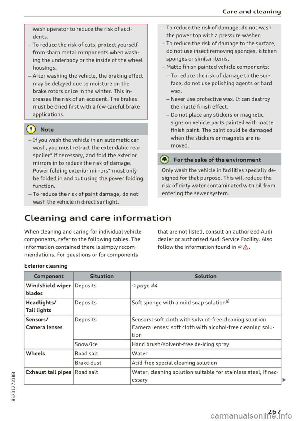
Exterior cleaning
Component Situation Solution
Windshield wiper
Deposits c::- page44
blades
Headlights /
Deposit s So
ft sponge wi th a m il d soap solutiona )
Tail light s
Sensors /
Deposits Sensors: soft cloth with solvent-free cleaning solut ion
Camera lenses Camera lenses: soft cloth w ith alcohol -free cleaning solu -
tion
Snow/ice H
and brus h/solvent-free de-icing spray
Wheels Road salt Water
Brake dust Acid-free special clean ing solution
Exhaust tail pipes Road salt Water, clea ning solution su itab le for stainless stee l, if nee-
essa ry
267
Page 284 of 314

Fuses and bulbs
Interior fuse assignment
Fig. 208 Vehicle inter ior: fuse assignme nt
No. Equipment
Fl Power top control modu
le (Roadster)
F2 Power top control module (Roadster)
F3 ESC control module
F4 Central computer processor (MIB-2)
FS Gateway
F6 Anti-theft alarm system Climate control system, selector lever (au-
F7 tomatic transmission), parking heater,
rear window heater relay coil
Diagnos is, electrical parking brake switch,
F8 light swi tch, rain/light sensor, interior
lighting
F9 Steering column switch module
Fl0 Display
F ll Haldex clutch
F12 MMI area
F 13 Adaptive dampers control module
F14 Climate control system blower
FlS Electronic steering co lumn lock
F16 MMI components, safety be
lt microphone
(Roadster)
282
No . Equipment
F17 Instrument cluster
F18 Rearview camera
F19 Convenience key system control module
F20 Power lumbar support adjustment
F22 Front passenger's side neck heating (Road-
ster)
F23 R
ig ht exterior lighting, on-board compute r
(right)
F 25 Driver's s
ide door (for example power win-
dows)
F26 Seat heating
F28 AMI H igh med ia port
F29 On-board computer
F31 Left on-board computer
F32 Driver assistance systems
F33 Airbag
Socket relay, interior sound, back-up light
F34 switch, temperature sensor, oil level sen-
sor
Diagnosis, headlight range control system,
F35 air quality sensor, automatic dimming
rearview mirror
F36 Right cornering light/ r ight LED-h eadlight
F37 Left cornering light/ left LED-headlight
F38 E
ng ine control module, ESC control mod-
ul e
F39 Front passenger's side door (for example
power windows)
F40 Cigarette lighter, sockets
F41 SCR relay and delivery unit
F42 Central locking area
F43 On-board computer
F45 Power adjustable driver's side seat
F46 Driver's side neck heat ing (Roadster)
F49 Starter, clutch sensor
FS0 ESC valves
F53 Rear window defogger
The power seats* are protected v ia
circuit break
ers
that automatically switch on after a few sec
onds after the overload has been reduced.
Page 285 of 314
CD
CD
.... N
" N .... 0 r--. V, co
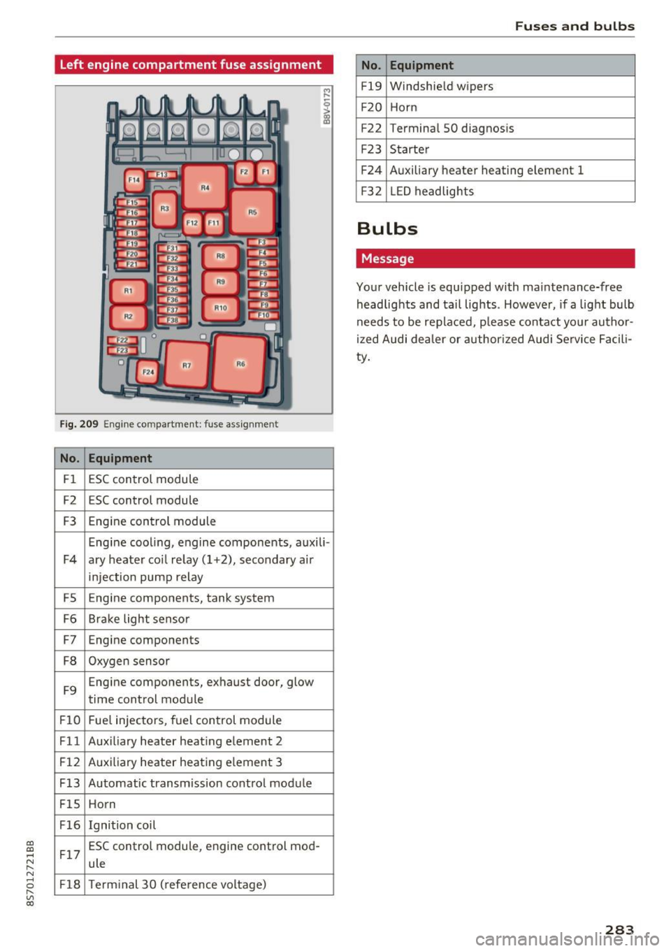
Left engine compartment fuse assignment
Fig. 209 Engine compartment: fuse ass ignment
No. Equipment
Fl ESC control module
F2 ESC control module
F3 Engine control module
Engine cooling, engine components, auxili -
F4 ary heater coil re lay ( 1+2), secondary air
injection pump relay
FS E
ngine components, tank system
F6 Brake light sensor
F7 Engine components
F8 Oxygen sensor
F9 Engine components, exhaust door, glow
time control module
FlO Fuel injectors, fuel control module
Fll Auxiliary heater heating element 2
F 12 Auxiliary heater heating e
lement 3
F13 Automatic transmission cont rol module
FlS Horn
F16 Ignition coil
F17 ESC control module
, engine control mod-
ule
F18 Term inal 30 (reference voltage)
Fuses and bulbs
No . Equipment
Fl9 Windshield wipers
F20 Horn
F22 Terminal SO diagnos
is
F23 Starter
F24 Auxiliary heater heating element 1
F3 2 LED headlights
Bulbs
Message
Your vehicle is equ ipped with maintenance-free
headlights and tail lights . However, if a light bulb
needs to be replaced, p lease contact yo ur author
ized Audi dea ler or authorized Audi Service Facili
ty.
283
Page 306 of 314
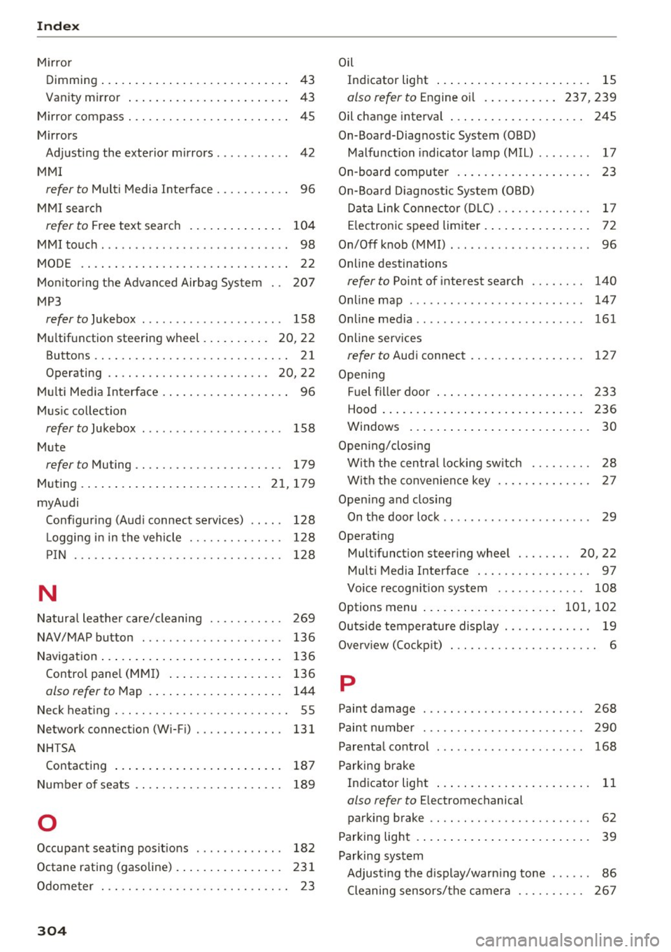
Index
Mirro r
D imming ... .... ... . ...... ... .. .. .... 43
Van ity m irror . . . . . . . . . . . . . . . . . . . . . . . . 43
M irro r compass . . . . . . . . . . . . . . . . . . . . . . . . 45
M irrors
Adj usti ng the exterio r m irrors. . . . . . . . . . . 42
M MI
refer to Multi Media Interface . . . . . . . . . . . 96
M MI searc h
refer to Free text search . . . . . . . . . . . . . . 104
MM I touch . . . . . . . . . . . . . . . . . . . . . . . . . . . . 98
M ODE . ... .. .. .. .. . .. ..... ... .. .. .... 22
Mon itor ing t he A dvan ced Airbag Sys tem 2 07
MP3
refer to Jukebo x . . . . . . . . . . . . . . . . . . . . . 158
Mul tifunction steering wheel . . . . . . . . . . 20, 22
Buttons.... .. .. ..................... 21
Operating . . . . . . . . . . . . . . . . . . . . . . . . 20, 22
Mul ti Med ia In terface . . . . . . . . . . . . . . . . . . . 96
Mus ic co llection
refer to Jukebox . . . . . . . . . . . . . . . . . . . . . 158
M ute
refer to Muting . . . . . . . . . . . . . . . . . . . . . . 179
Mu ting . . . . . . . . . . . . . . . . . . . . . . . . . . . 21, 179
myAudi Configuring (Aud i connect se rvic es) . . . . . 128
L ogging i n in the vehicle . . . . . . . . . . . . . . 128
PI N . . . . . . . . . . . . . . . . . . . . . . . . . . . . . . . 128
N
Natura l leather care/cleaning . . . . . . . . . . . 269
NAV/MAP button . . . . . . . . . . . . . . . . . . . . . 136
Navigat ion . . . . . . . . . . . . . . . . . . . . . . . . . . . 136
Contro l pane l (MMI) . . . . . . . . . . . . . . . . . 136
also refer to Map . . . . . . . . . . . . . . . . . . . . 144
Neck heat ing . . . . . . . . . . . . . . . . . . . . . . . . . . 55
Network connection (W i-F i) . . . . . . . . . . . . . 131
NHTSA Contacting . . . . . . . . . . . . . . . . . . . . . . . . . 187
Number of seats . . . . . . . . . . . . . . . . . . . . . . 189
0
Occupant seating posit ions . . . . . . . . . . . . . 182
Octane rating (gasoline) . . . . . . . . . . . . . . . . 231
Odome ter . . . . . . . . . . . . . . . . . . . . . . . . . . . . 23
304
Oil
Indicator light . . . . . . . . . . . . . . . . . . . . . . . 15
also refer to Engine o il .. . ... .... . 237, 239
Oil ch ange inte rva l . . . . . . . . . . . . . . . . . . . . 245
On-Boa rd-Diag nostic System (OBD)
Malfunction indicato r lamp (MIL) . . . . . . . . 17
On -board computer . . . . . . . . . . . . . . . . . . . . 23
On-Boa rd Diagnos tic System (OBD)
Dat a Link Conne cto r (DL C) . . . . . . . . . . . . . . 17
El ectronic s peed limiter . . . . . . . . . . . . . . . . 72
On/Off knob ( MMI) . . . . . . . . . . . . . . . . . . . . . 96
Online destinations
refer to Point of interest search . . . . . . . . 140
Online m ap . . . . . . . . . . . . . . . . . . . . . . . . . . 147
Online media . . . . . . . . . . . . . . . . . . . . . . . . . 161
Online services
refer to Aud i connect . . . . . . . . . . . . . . . . . 127
Open ing
Fuel f iller doo r . . . . . . . . . . . . . . . . . . . . . . 2 33
Hood .. ... .. .. .. .. .. ... . .. .... ... .. 2 36
Windows ... .. .. .. .. .. .. .. .... ... .. . 30
Open ing/clos ing
Wi th the centr al locking sw itch . . . . . . . . . 28
With the convenience key . . . . . . . . . . . . . . 27
Open ing and closing
On the door loc k . . . . . . . . . . . . . . . . . . . . . . 29
Operat ing
Mult ifunct io n steer ing whee l . . . . . . . . 20, 22
Mult i Media Interface . . . . . . . . . . . . . . . . . 97
Vo ice recog nitio n system . . . . . . . . . . . . . 108
Options menu . . . . . . . . . . . . . . . . . . . . 101, 102
Outs ide temperat ure display . . . . . . . . . . . . . 19
Overv iew (Cockp it) . . . . . . . . . . . . . . . . . . . . . . 6
p
Paint damage
268
Pain t numbe r . . . . . . . . . . . . . . . . . . . . . . . . 290
Pare nta l co ntro l . . . . . . . . . . . . . . . . . . . . . . 168
Par king brake
Ind icator light . . . . . . . . . . . . . . . . . . . . . . . 11
also refer to Electromechanical
par king brake . . . . . . . . . . . . . . . . . . . . . . . . 62
Parking light . . . . . . . . . . . . . . . . . . . . . . . . . . 39
Parking system Adjust ing t he d ispl ay/warn ing tone . . . . . . 86
Cleaning sensors/the camera . . . . . . . . . . 267