rear view mirror AUDI TT ROADSTER 2018 Owners Manual
[x] Cancel search | Manufacturer: AUDI, Model Year: 2018, Model line: TT ROADSTER, Model: AUDI TT ROADSTER 2018Pages: 310, PDF Size: 46.95 MB
Page 9 of 310
Cl 00 .-< N r-N .-< 0 r-Vl 00
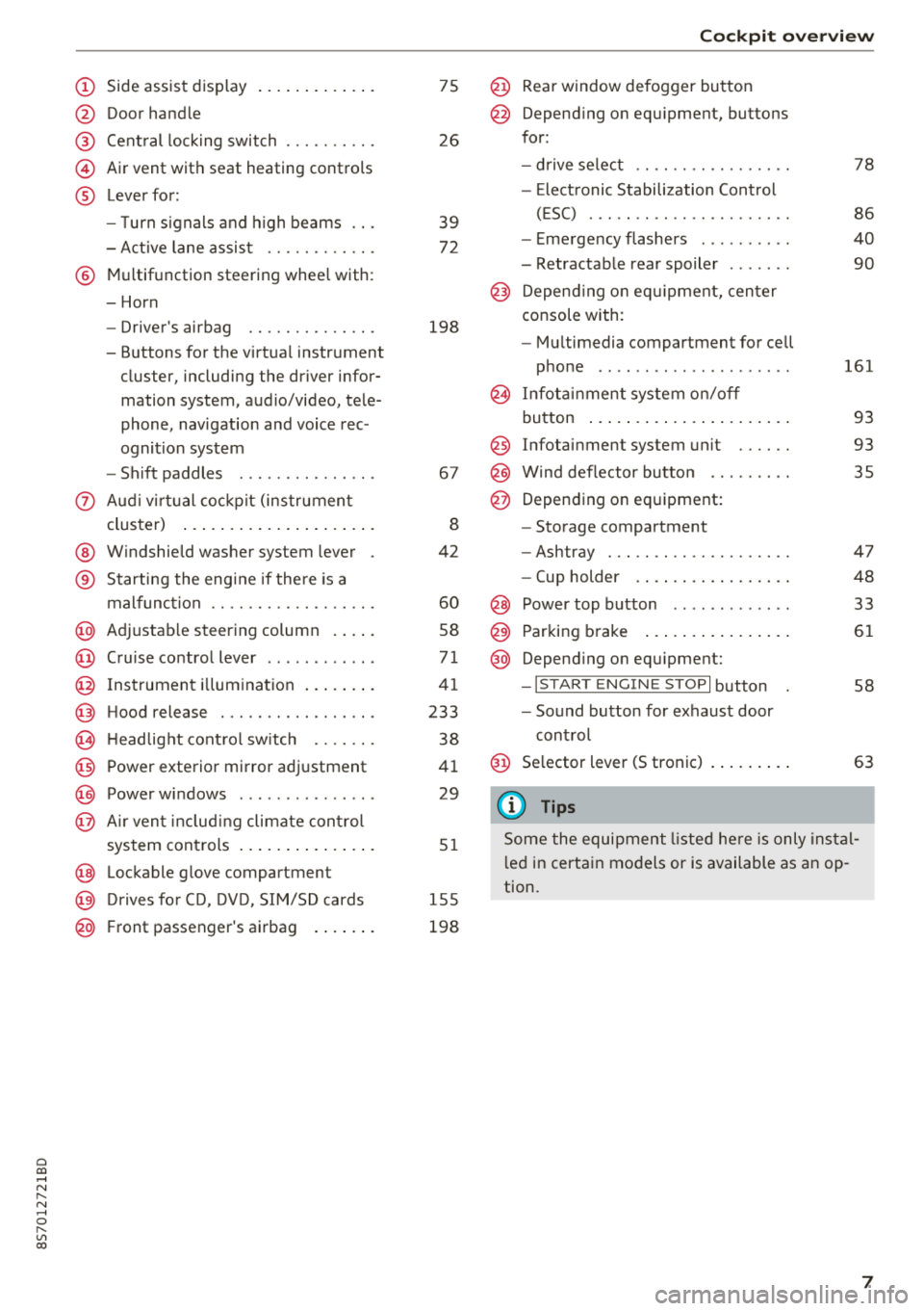
(D Side assist disp lay ..... ... .. .. .
@ Door handle
@ Cent ral locking swit ch ..... .. .. .
@ Air vent with seat heating controls
® Lever for:
- T urn s ignals and high beams
- Act ive lane assist ....... .. .. .
® M ultifunction steering whee l with :
- Horn
- Driver's airbag ........... .. .
- Buttons for the virtua l instr ument
cluster, including the dr iver infor
mation system, audio/video, tele
phone, navigation and voice rec
ognit ion system
- Shift paddles ............. . .
(J) A ud i v irtu al coc kp it (instrument
cluster) ... ... .. ..... ... .. .. .
@ W indshield washer system lever
® Starting the eng ine if the re is a
malfunc tion ............... .. .
@ Ad justable steer ing column . ... .
@ Cruise contro l lever .......... . .
@ Ins trumen t il lum ination ... .. .. .
@ Hood release .............. .. .
€3) H eadlight cont ro l sw itch .... .. .
@ Power exterio r mirror adj ustment
@) Power windows .............. .
@ A ir ven t incl uding climate con trol
system controls .. ..... ... .. .. .
@ Lockable g love compartment
@) D rives fo r CD, DV D, SIM/SD cards
@ Front passenger's ai rbag . ... .. .
75
26
39
7 2
198
67
8
42
60
58
71
41
233
38
4 1
29
5 1
1 55
198
Coc kpit o ver view
@ Rear window defogger button
@ Depend ing on equ ipment, buttons
for:
- drive select .. .............. .
- Elect ronic Stabili zation Cont rol
( E SC) . .. .. .. .............. .
- E me rge ncy flashers ......... .
- Retractable rear spoiler ...... .
@ Depending o n eq uipment, cen ter
console with:
- Mu ltimedia compartment for cell
p hone .. .. .. .. ............ .
@ In fota inment system o n/off
bu tton ... .... .. ... .. ..... .. .
@ Infotai nment system unit ..... .
@ Wind deflector butto n ........ .
@ Depending on eq uipment:
- Storage compartment
- Ashtray . .. .. .............. .
- Cup holder .... ... .. ..... .. .
@ Power top b utton ............ .
@ Parking b rake ... ... .. ..... .. .
@ Depend ing on eq uipment:
-I S TAR T ENGI NE STOP I button
- So und button for exhaust door
cont rol
@ Se lector lever (S tronic)
(D Tips
78
86
40
90
161
93
93 35
47
48
33
61
58
63
Some the equi pment listed he re is only ins tal
l e d in certa in models or is available as an op
tion.
7
Page 29 of 310
Cl co ..... N ,....
N ...... 0
Fold mirrors* -if yo u se lec t On , the exterior rear
view mirrors fold in automatically when you press
the
[ml button on the remote cont rol key o r touch
the sensor* in the hand le.
Lo ck when driving1> -if you select On , the vehicle
l oc ks automatically when driving . A ll of the doors
and the luggage compa rtment lid lock.
Mechanically unlocking and locking the
doors
If the central locking fails , you mus t unlock/lock
t he doors separa tely.
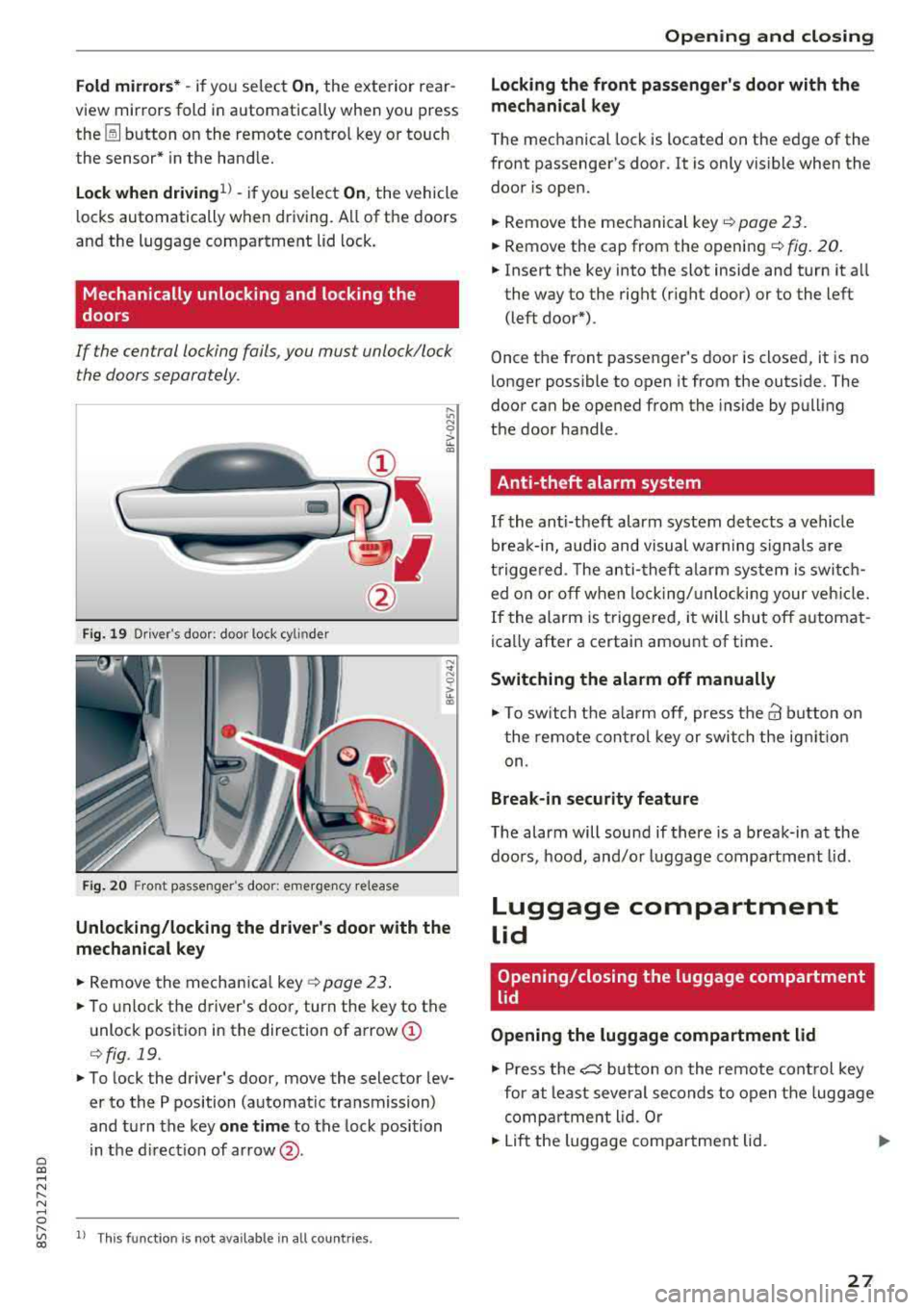
F ig. 19 Dr iver 's door: doo r loc k cy lin der
F ig. 20 Fro nt passenger 's doo r: e merge ncy re lease
Unlocking/locking the driver's door with the
mechanical key
.. Remove the mechan ica l key o:!> page 23 .
.. To unlock the driver's doo r, turn the key to the
unlock positio n in the direction of arrow
(I)
r=> fig . 19.
.. To lock the driver's door, move the selector lev
er to the P position (automat ic tra nsmission)
and tu rn the key
one t ime to the lock position
in the d irect ion of ar row @.
,....
"' l) Thi s fun ctio n is not avail able in al l coun tries. co
Opening and closing
Locking the front passenger's door with the
mechanical key
The mechanical lock is located on the edge of the
front passenger's door . It is only vis ible when the
door is open.
.. Remove the mechanical key .:!> page 23.
.. Remove the cap from the openi ng ¢ fig . 20 .
.. Insert the key into the slot inside and turn it a ll
the way to the right (r ight door) or to the left
(left door*).
Once the front passenger 's door is closed, it is no
longer possible to open it from the outs ide . The
door can be opened from the inside by pull ing
t h e door handle.
Anti-theft alarm system
If the anti-theft alarm system detects a vehicle
brea k-in, audio and visual warn ing signals are
t rigge red. The anti -theft a la rm sys tem is swi tc h
ed o n or off when lock ing/ unlo cki ng your ve hicle.
If the alarm is triggered, i t will shut off a utomat
ica lly after a certain amount of time.
Switching the alarm off manually
.,. To swit ch t he a la rm off, press t he@ b utton on
t he remote cont rol key o r switch the ig nit io n
on.
Break-in security feature
T he alarm will sound if there is a break-in at the
doo rs , hood, and/o r luggage compa rtment lid.
Luggage compartment
lid
Opening/closing the luggage compartment
lid
Opening the luggage compartment lid
.,. Press the e5 button on the remote con trol key
for at least severa l seconds to open the luggage
comp artment lid. Or
.. Lift the luggage compa rtment lid . ..,_.
27
Page 32 of 310
Opening and clo sin g
Correcting power w indow malfunctions
You can reactivate the one-touch up/down func
tion if it malfunctions .
.. Pull the power window sw itch up unt il the win
dow is completely raised.
.. Release the sw itch and pull it up again for at
least one second .
Garage door opener
(Homelink)
Description
Applies to: vehicles with garage door opener (Homelink)
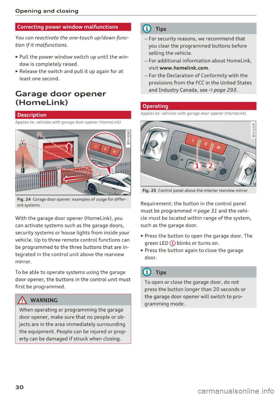
Fig . 24 Garage door ope ner: exa mples o f usage fo r differ
ent systems
W ith the garage door opener (Homelin k), you
can activate systems such as the garage doors,
secur ity systems o r house lights from inside your
veh icle. Up to three remote control f unctions can
be programmed to the three buttons that are in
tegrated in the control unit above the rearview
mirror .
To be ab le to operate systems using the garage
door opener, the buttons in the contro l unit must
first be programmed .
A WARNING
When operating or programming the garage
door opener, make sure that no people or ob
jects are in the area immediately surrounding
the equipment . Peop le can be injured or prop
erty can be damaged if str uck when closing .
30
@ Tips
-For security rea.sons, we recommend that
you clear the programmed buttons before
selling the vehicle .
- For additiona l information about Homelink,
visit
www.homeli nk.com .
-For the Dec laration of Conformity with the
prov isions from the FCC in the United States
and Industry Canada, see
c;, page 293.
Operating
App lies to : vehicles with garage door opener (Homelink)
F ig . 25 Co ntro l pane l above t he inter ior rea rv iew mirror
Requirement: the button in the control panel
must be
programmed ¢ page 31 and the vehi
cle must be located within range of the system,
such as the garage door.
.. Press the button to open the garage door . The
green
LED © blinks or turns on .
.. Press the button aga in to close the garage
door.
(D Tips
To open or close the garage door, do not
press the button longer than 20 seconds or
the garage door opener will switch to pro gramming mode.
Page 41 of 310
Cl co .... N ,..._
N .... 0 ,..._
Vl co
turned on in accordance with traffic
reg ulations.
- If the battery has been discharging for a
while, the parking light may sw itch off auto
matically. A lways make sure your vehicle is
parked and adequately lit according to the
laws . Avo id using the parking lights for sev
era l hours.
- Always observe legal reg ulat ions when us
ing the light ing systems described.
(!') Tips
- The light sensor for the automatic head
lights* is in the rearview mirror mount. Do
not place any stickers in this area on the
windsh ield.
- Some exterior lighting fu nctions can be ad
j usted
c::> page 39.
- If you turn off the ignition wh ile the exterio r
lights are on and open the door, a warning
tone so unds.
- In some markets, the ta il lights will sw itch
on when the dayt ime runn ing lights sw itch
on.
- In cool o r damp weather, the inside of the
headlig hts, tu rn s ignals and tai l lights can
fog over d ue to the tem perature d ifference
betwee n the inside and ou ts ide. They will
clea r shor tly after sw itch ing them o n. This
d oes not aff ect t he serv ice life o f the lig ht
i ng.
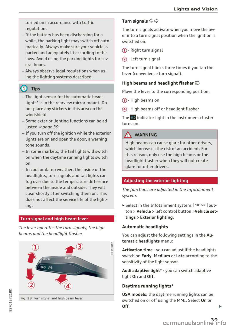
Turn signal and high beam lever
The lever opera tes the turn sign als, the high
beams and the headlight flasher .
Fig . 38 Tu rn signal an d high beam lever
N
0
~
"'
Lights and V ision
Turn signals ¢ 9
The turn signa ls act ivate w hen yo u move the lev
er into a turn signa l posit io n when the igni tion is
switched on .
©-Righ t turn signal
@ -Left tur n signal
The turn signa l blinks three t imes i f you tap t he
lever (convenience t urn signa l).
High beams and headlight flasher
~D
Move t he lever to the corresponding position:
@ -High beams o n
@-High beams off or headlight flasher
T he
II indicato r light in t he inst rument cl uster
turns on .
A WARNING
-High beams can cause glare for other drivers,
which increases the risk of an accident. Fo r
this reaso n, only use the high beams or the
headlight flasher when they wil l not create
g la re fo r ot her dr ivers.
Adjusting the exterior lighting
The functions are adjusted in the Infotainment
system .
.,. Select in the Infotainment system: I MENU ! but
ton> Vehicle > left control button >Vehicle set
tings > Exterior lighting .
Automatic headlights
You can adjust the following sett ings in the Au
tomatic headlights menu:
Activation time
-you can a djust if the headlights
switch on Early, Medium or Late according to the
sensit ivity of the light sensor.
Audi adaptive light * -you can sw itch ad ap tive
li gh t
On and Off .
Daytime running lights*
USA models: the daytime runn ing ligh ts can be
switched on or off using the MM I. Se lec t
On or
Off .
39
Page 44 of 310
Lights and Vision
Dimming the mirrors
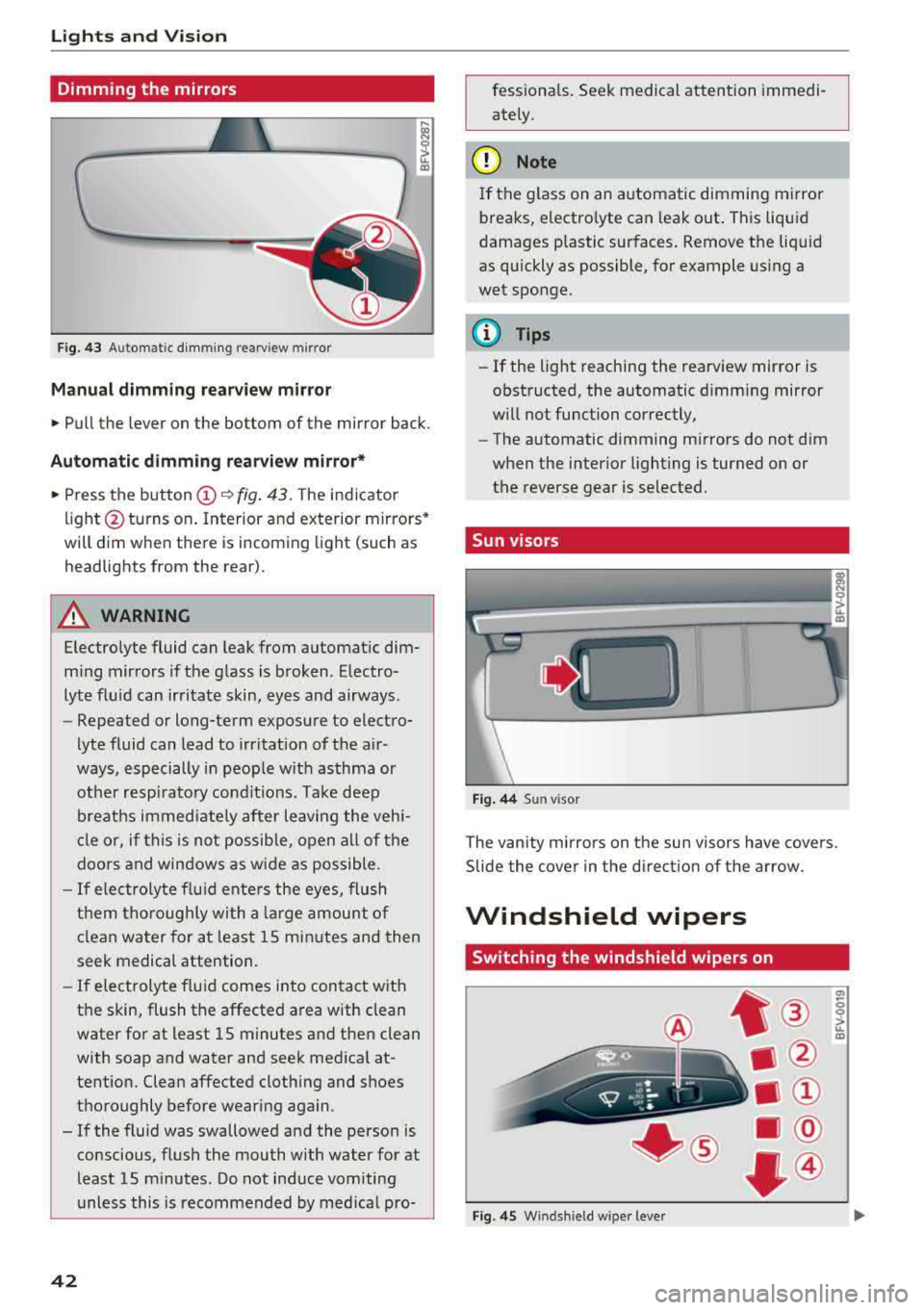
Fig. 43 Automatic dimming rearview mirror
Manual dimming rea rview mirror
• Pull the lever on the bottom of the mirror back.
Automatic dimming rearview mirror*
• Press the button (D ~ fig. 43. The indicator
light @turns on . Interior and exterior mirrors*
will dim when there is incoming light (such as
headlights from the rear) .
A WARNING
Electrolyte fluid can leak from automatic dim
m ing mirrors if the glass is broken. Electro
lyte fluid can irritate skin, eyes and airways.
- Repeated or long-term exposure to electro-
lyte fluid can lead to irritation of the a ir
ways, especially in people with asthma or
other resp irato ry conditions. Take deep
breaths immed iate ly after leaving the vehi
cle or, if this is not possible, open all of the
doors and windows as wide as possible .
-If electrolyte f lu id ente rs the eyes, flush
them thoroughly with a large amount of
clean water for at least 15 minutes and then
seek medical attention.
- If electrolyte f luid comes into contact with
the skin, flush the affected area with clean
water for at least 15 minutes and then clean
with soap and water and seek medical at
tention. Clean affected clothing and shoes
thoroughly before wearing again .
- If the fluid was swallowed and the person is conscious, flush the mouth with water for at
least 15 minutes. Do not induce vomiting
unless this is recommended by med ical pro-
42
fessionals . Seek medical attention immedi
ately .
(D Note
If the glass on an automatic dimming mirror
breaks, electro lyte can leak out . This liquid
damages plastic surfaces. Remove the liquid
as quickly as possible, for example us ing a
wet sponge.
(D Tips
- If the light reaching the rearview mirror is
obstructed, the automatic dimming mirror
will not function correctly,
- The automatic dimming mirrors do not dim
when the interior lighting is turned on or
the reverse gear is selected.
Sun visors
Fig. 44 Sun visor
T he vanity mirrors on the sun visors have covers .
Slide the cover in the direction of the arrow.
Windshield wipers
Switching the windshield wipers on
Fig . 45 W inds hield w iper leve r
(7>
0 0 > u. m
Page 46 of 310
Lights and Vision
& WARNING
Dirty windshield wiper blades can impair vi
sion, which increases the risk of an accident .
Replacing windshield wiper blades
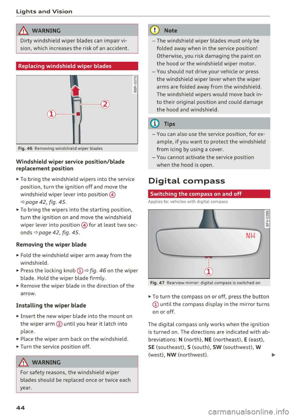
Fig. 46 Removing w inds hield w iper b lades
Windshield wiper service position/blade
replacement position
"' ij
a:: CX) m
,.. To bring the windshield wipers into the service
position, turn the ignition off and move the
windshield wiper lever into position@
¢ page 42, fig. 45 .
,.. To bring the wipers into the starting pos it io n,
turn the ignition on and move the windsh ield
wiper lever into position @ for at least two sec
onds¢ page 42, fig. 45.
Removing the wiper blade
,.. Fold the windshield wiper arm away from the
windshield.
,.. Press the locking knob@¢ fig. 46 on the wiper
blade . Hold the wiper blade firmly.
,.. Remove the wiper blade in the direction of the
arrow.
Installing the wiper blade
,.. Insert the new wiper b lade into the mount on
the wiper arm@until you hear it latch into
place.
,.. Place the wiper arm back on the windshield.
,.. Turn the service position off.
& WARNING
-
For safety reasons, the windshie ld wiper
blades should be replaced once or twice each
year.
44
(D Note
- Th e windshie ld wiper blades must only be
folded away when in the service position!
Otherwise, you risk damaging the paint on
the hood or the windshield wiper motor.
- You should not drive your vehicle or press the windshield wiper lever when the wiper
arms are folded away from the windshield.
The windshield w ipers would move back in
to their original position and could damage
the hood and windshield.
a) Tips
- You can also use the service posit ion, for ex
ample, if you want to protect the windshield
from icing by using a cover .
- You cannot activate the service posit ion
when the hood is open .
Digital compass
Switching the compass on and off
Applies to: vehicles wit h digital compass
Fig. 47 Rearview m irror: d ig ital compass is sw itched on
l!l
"' 0
> ... m
,.. To turn the compass on or off, press the button
@ until the compass display in the mirror turns
on or off.
The dig ital compass only works when the ignit ion
is turned on . The directions are indicated with ab
breviations:
N (north), NE (northeast), E (east),
SE (southeast), S (south), SW (southwest), W
(west), NW (northwest).
Page 47 of 310
Cl co .... N ,..._
N .... 0 ,..._
Vl co
(D Tips
To prevent inaccurate compass readings, do not bring any remote controls, e lectr ica l devi
ces or metallic objects near the mirror .
Adjusting the magnetic zone
Applies to: vehicles with digital compass
I
I I
' I
I I
®
' ' ' '
®
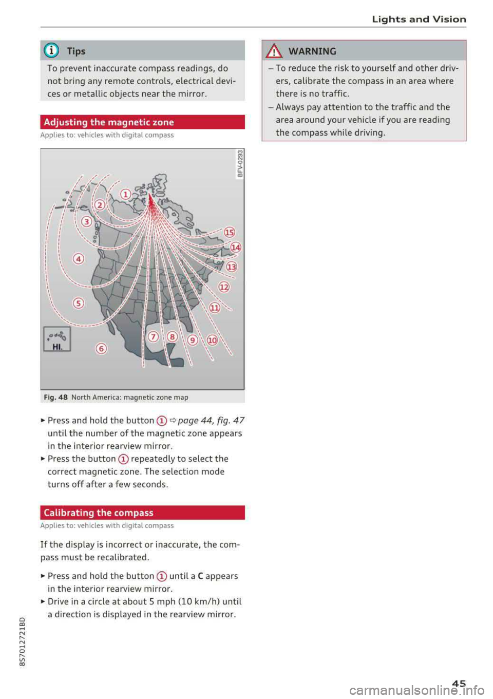
Fig. 48 Nort h Ame rica: mag netic zo ne map
~ N 0
> u. ID
• Press and hold the button (D Q page 44, fig . 47
until the number of the magnetic zone appears
in the interior rearview mirror .
• Press the button (D repeatedly to select the
correct magnetic zone . The select ion mode
turns off after a few seconds.
Calibrating the compass
Applies to: vehicles with digital compass
If the display is incorrect or inaccurate, the com
pass must be recalibrated.
• Press and hold the button (D until a C appears
in the interior rearview mirror .
.,. Drive in a circle at about 5 mph ( 10 km/h) until
a direction is displayed in the rearview mirror .
Lights and Vision
A WARNING
-To reduce the risk to yourself and other driv
ers, calibrate the compass in an area where
there is no traffic.
- Always pay attention to the traffic and the
area around your vehicle if you are reading
the compass while driving .
45
Page 78 of 310
Assistance systems
The display remains dim in the information stage
so that your view toward the front is not distur
bed .
Warning stage
If you activate the turn signa l, side assist warns
you abou t veh icles that are detected and classi
fied as critical. The display in the respective mir
ror blinks brightly. If this happens, check traffic
by glancing in the exterior mirrors and over your
shoulder
c:> .& in General information on
page
77.
(D Tips
You can ad just the brightness on of the dis
play on the rearview mirror
c:> page 77.
General information
Applies to: vehicles with Audi side assist
®
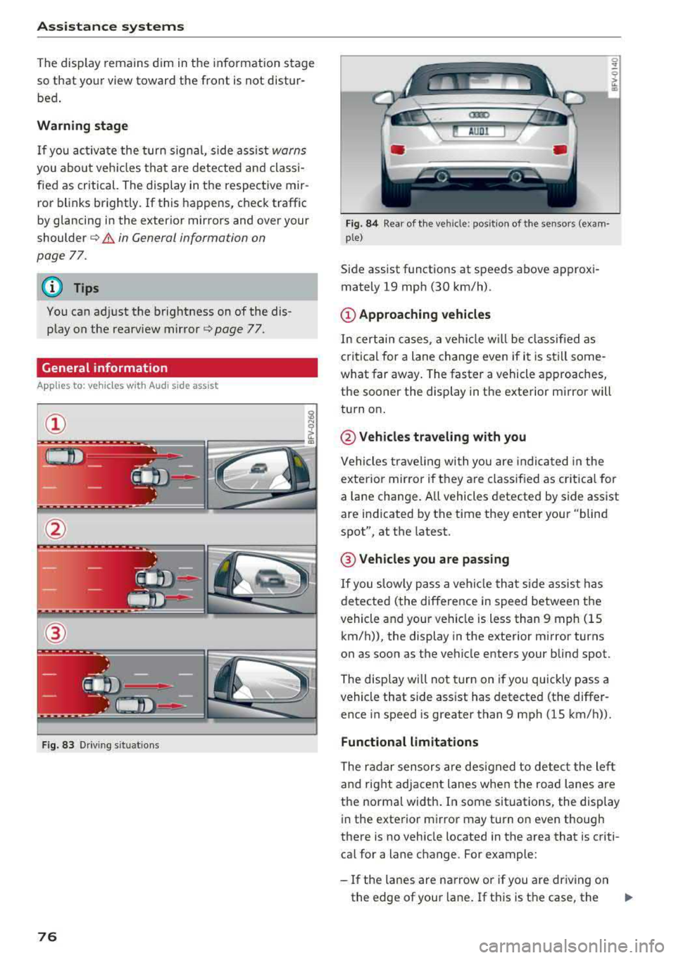
Fig. 83 Driving situat ions
76
Fig. 84 Rear of the veh icle: pos it ion of the sensors (exam·
p le)
Side assist funct ions at speeds above approxi
mately 19 mph (30 km/h) .
(D Approaching vehicles
In certain cases, a vehicle w ill be class ified as
c ritical for a lane change even if it is still some
what far away. The faster a vehicle approaches,
the sooner the display in the exterior m irror will
turn on.
@ Vehicles traveling with you
Vehicles traveling with you are indica ted in the
exterior mirror if t hey are classified as critical for
a lan e change. A ll vehicles detected by side assist
are indicated by the time they enter your "blind
spot", at the latest.
@ Vehicles you are passing
If you slowly pass a vehicle that side assist has
detected (the difference in speed between the
vehicle and your vehicle is less than 9 mph (15 km/h)), the display in the exterior mirror turns
on as soon as the vehicle enters your blind spot.
The display wi ll not turn on if you quickly pass a
vehicle that side ass ist has detected (the differ
ence in speed is greater than 9 mph (15 km/h)).
Functional limitations
The radar sensors are designed to detect the left
and right adjacent lanes when the road lanes are
the norma l width . In some situations, the display
in the exterior mirror may turn on even though
there is no vehicle located in the area that is criti
cal for a lane change. For example:
-If the lanes are narrow or if you are driving on
the edge of your lane . If this is the case, the
.,,_
Page 85 of 310
Cl co .... N ,....
N ...... 0 ,....
Vl co
General information
Applies to: ve hicles with rearview camera
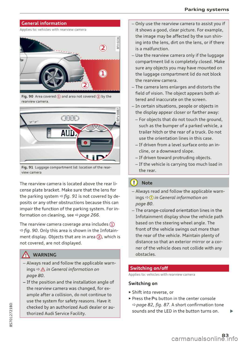
Fig . 90 Area covered (!) and area not covered @ by the
rea rview camera.
:;,
~;..------: :.·~- ---~ _.,- ,.,,.--------g
(Jo00oD ~
Fig. 91 Luggag e compartment lid: locat ion of the rear
view camera
The rearview camera is located above the rear li
cense plate bracket. Make sure that the lens for
the parking system¢
fig. 91 is not covered by de
posits or any other obstructions because this can
impair the function of the parking system. For in
formation on cleaning, see¢
page 266 .
The rearview camera coverage area includes
(D
¢ fig. 90. Only this area is shown in the Infotain
ment display. Objects that are in
area @, which is
not covered, are not displayed.
A WARNING
-Always read and follow the applicable warn
ings ¢
A in General information on
page 80.
- If the position and the installation angle of
the rearv iew camera was changed, for ex
ample after a collision, do not continue to
use the system for safety reasons. Have it
checked by an authorized Audi dealer or au
thorized Audi Service Facility .
Parking systems
-Only use the rearview camera to assist you if
it shows a good, clear picture. For example,
the image may be affected by the sun shin
ing into the lens, dirt on the lens, or if there
is a malfunction.
- Use the rearview camera only if the luggage
compartment lid is completely closed. Make
sure any objects you may have mounted on
the luggage compartment lid do not block
the rearview camera.
- The camera lens enlarges and distorts the
field of vision. The object appears both al
tered and inaccurate on the screen.
- In certain situations, people or objects in
the display appear closer or farther away:
- For objects that do not touch the ground,
such as the bumper of a parked vehicle, a
trailer hitch or the rear of a truck. Do not use the orientation lines in this case.
- If driven from a level surface onto an in cline, or a downward slope .
- If driven toward protruding objects.
- If the vehicle is carrying too much load in
the rear.
(D Note
-Always read and follow the applicable warn
ings
¢ (D in General information on
page 80.
- The orange-colored orientation lines in the
Infotainment display show the vehicle path
based on the steering wheel angle. The
front of the vehicle swings out more than
the rear of the vehicle. Maintain plenty of
distance so that an exterior mirror or a cor
ner of the vehicle does not collide with any
obstacles.
Switching on/off
App lies to : vehicles wi th rearv iew camera
Switching on
.,. Shift into reverse, or
.,. Press the P,q.A button in the center console
¢ page 82, fig. 87. A short confirmation tone
sounds and the LED in the button turns on.
..,.
83
Page 283 of 310
Cl co .... N ,....
N ...... 0 ,....
Vl co
Interior fuse assignment
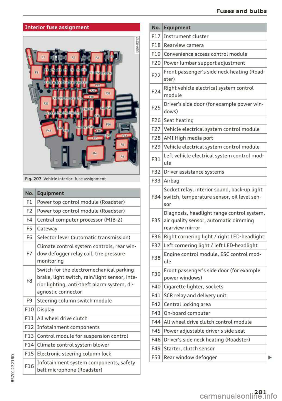
Fig. 207 Vehicle interior: fuse assignmen t
No. Equipment
Fl Power top cont
rol module (Roadster)
F2 Power top control module (Roadster)
F4 Central computer processor (MIB
-2)
FS Gateway
F6 Selector lever (automatic transmission)
Climate control system controls, rear w in-
F7 dow defogger relay coil, tire pressure
mon itoring
Switch for the electromechanical parking
F8 brake, light switch, rain/light sensor, inte-
rior lighting, anti -theft alarm system, di -
agnostic connector
F9 Steering column switch module
FlO Display
Fll All whee
l drive clutch
F12 Infotainment components
F13 Control module for suspension control
F14 Climate control system blowe r
FlS Electronic steering column
lock
F16 I
nfotainment system components, safety
be lt microphone (Roadster)
No.
Fl7
F1 8
Fl9
F20
F 22
F24
F 25
F 26
F 27
F28
F2 9
F 31
F3 2
F33
F 34
F 35
F36
F37
F3 8
F39
F40
F41
F 42
F43
F44
F45
F46
F49
F S3
Fuses and bulbs
Equipment
Instrument cluster
Rearview camera
Convenience access control module
Power lumbar support adjustment
Front passenger's side neck heating (Road-
ster)
R ight vehicle electrica l system control
module
Driver's s ide door (for example power w in-
dows)
Seat heating
Vehicle electrical system control module
AMI High media port
Vehicle e lectr ical system control module
Left vehicle electrical system contro l mod-
ule
Driver assistance systems
Airbag
Socket relay, inte rior sound , back-up light
switch, temperature sensor, oil leve l sen -
sor
Diagnosis, headlight range control system,
a ir quality sensor, automatic dimming
rearview mirror
R ight cornering light/ right LED-headlight
L eft cornering light/ left LED-headlight
Engine control module, ESC control mod-
ule
Front passenger's side door (for example
power windows)
C igarette lighter, sockets
SCR relay and delivery unit
Central locking area
On-board computer
A ll wheel d rive clutch control module
Power adjustable driver's side seat
Driver's side neck heating (Roadster)
Starter, clutch sensor
Rear window defogger
281