low BMW 228I COUPE 2016 Owners Manual
[x] Cancel search | Manufacturer: BMW, Model Year: 2016, Model line: 228I COUPE, Model: BMW 228I COUPE 2016Pages: 232, PDF Size: 5.76 MB
Page 182 of 232

Minimum tread depth
Wear indicators are distributed around the
tire's circumference and have the legally re‐
quired minimum height of 0.063 in/1.6 mm.
They are marked on the side of the tire with
TWI, Tread Wear Indicator.
Tire damage
General information
Inspect your tires often for damage, foreign
objects lodged in the tread, and tread wear.
Hints
Driving over rough or damaged road surfaces,
as well as debris, curbs and other obstacles
can cause serious damage to wheels, tires and
suspension parts. This is more likely to occur
with low-profile tires, which provide less cush‐
ioning between the wheel and the road. Be
careful to avoid road hazards and reduce your
speed, especially if your vehicle is equipped
with low-profile tires.
Indications of tire damage or other vehicle de‐
fects:
▷Unusual vibrations while driving.▷Unusual handling such as a strong ten‐
dency to pull to the left or right.
Damage can, e. g., be caused by driving over
curbs, road damage, or similar things.
In case of tire damage
If there are indications of tire damage, re‐
duce your speed immediately and have the
rims and tires checked right away; otherwise,
there is the increased risk of an accident.
Drive carefully to the nearest service center. If
necessary, have the vehicle towed or trans‐
ported there. Otherwise, tire damage can be‐
come life threatening for vehicle occupants
and also other traffic.◀
Repair of tire damage
For safety reasons, the manufacturer of
your vehicle recommends that you do not have
damaged tires repaired; they should be re‐
placed. Otherwise, damage can occur as a re‐
sult.◀
Changing wheels and tires
Mounting Information on mounting tires
Have mounting and balancing performed
only by a service center.
If work is not carried out properly, there is a
danger of subsequent damage and related
safety hazards.◀
Wheel and tire combination
You can ask the service center about the right
wheel/tire combination and wheel rim versions
for the vehicle.
Incorrect wheel and tire combinations impair
the function of a variety of systems such as
ABS or DSC.
To maintain good handling and vehicle re‐
sponse, use only tires with a single tread con‐
figuration from a single manufacturer.
Following tire damage, have the original wheel
and tire combination remounted on the vehicle
as soon as possible.Seite 178MobilityWheels and tires178
Online Edition for Part no. 01 40 2 961 270 - II/15
Page 184 of 232
StorageStore wheels and tires in a cool, dry place with
as little exposure to light as possible.
Always protect tires against all contact with oil,
grease and fuels.
Do not exceed the maximum tire inflation pres‐
sure indicated on the side wall of the tire.
Run-flat tires Label
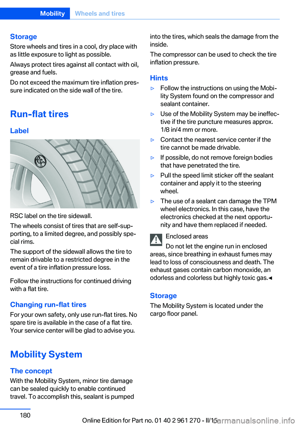
RSC label on the tire sidewall.
The wheels consist of tires that are self-sup‐
porting, to a limited degree, and possibly spe‐
cial rims.
The support of the sidewall allows the tire to
remain drivable to a restricted degree in the
event of a tire inflation pressure loss.
Follow the instructions for continued driving
with a flat tire.
Changing run-flat tires
For your own safety, only use run-flat tires. No
spare tire is available in the case of a flat tire.
Your service center will be glad to advise you.
Mobility System
The concept With the Mobility System, minor tire damagecan be sealed quickly to enable continued
travel. To accomplish this, sealant is pumped
into the tires, which seals the damage from the inside.
The compressor can be used to check the tire inflation pressure.
Hints▷Follow the instructions on using the Mobi‐
lity System found on the compressor and
sealant container.▷Use of the Mobility System may be ineffec‐
tive if the tire puncture measures approx.
1/8 in/4 mm or more.▷Contact the nearest service center if the
tire cannot be made drivable.▷If possible, do not remove foreign bodies
that have penetrated the tire.▷Pull the speed limit sticker off the sealant
container and apply it to the steering
wheel.▷The use of a sealant can damage the TPM
wheel electronics. In this case, have the
electronics checked at the next opportu‐
nity and have them replaced if needed.
Enclosed areas
Do not let the engine run in enclosed
areas, since breathing in exhaust fumes may
lead to loss of consciousness and death. The
exhaust gases contain carbon monoxide, an
odorless and colorless but highly toxic gas.◀
Storage The Mobility System is located under the
cargo floor panel.
Seite 180MobilityWheels and tires180
Online Edition for Part no. 01 40 2 961 270 - II/15
Page 186 of 232
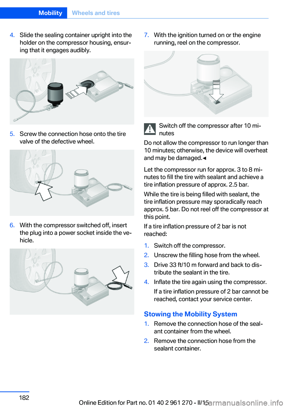
4.Slide the sealing container upright into the
holder on the compressor housing, ensur‐
ing that it engages audibly.5.Screw the connection hose onto the tire
valve of the defective wheel.6.With the compressor switched off, insert
the plug into a power socket inside the ve‐
hicle.7.With the ignition turned on or the engine
running, reel on the compressor.
Switch off the compressor after 10 mi‐
nutes
Do not allow the compressor to run longer than
10 minutes; otherwise, the device will overheat
and may be damaged.◀
Let the compressor run for approx. 3 to 8 mi‐
nutes to fill the tire with sealant and achieve a
tire inflation pressure of approx. 2.5 bar.
While the tire is being filled with sealant, the
tire inflation pressure may sporadically reach
approx. 5 bar. Do not reel off the compressor at
this point.
If a tire inflation pressure of 2 bar is not
reached:
1.Switch off the compressor.2.Unscrew the filling hose from the wheel.3.Drive 33 ft/10 m forward and back to dis‐
tribute the sealant in the tire.4.Inflate the tire again using the compressor.
If a tire inflation pressure of 2 bar cannot be
reached, contact your service center.
Stowing the Mobility System
1.Remove the connection hose of the seal‐
ant container from the wheel.2.Remove the connection hose from the
sealant container.Seite 182MobilityWheels and tires182
Online Edition for Part no. 01 40 2 961 270 - II/15
Page 187 of 232
3.Wrap the empty sealant container and con‐
nection hose in suitable material to avoid
dirtying the cargo area.4.Stow the Mobility System back in the vehi‐
cle.
Distributing the sealant
Immediately drive approx. 5 miles/10 km to en‐
sure that the sealant is evenly distributed in the
tire.
Do not exceed a speed of 50 mph/80 km/h.
If possible, do not drive at speeds less than
12 mph/20 km/h.
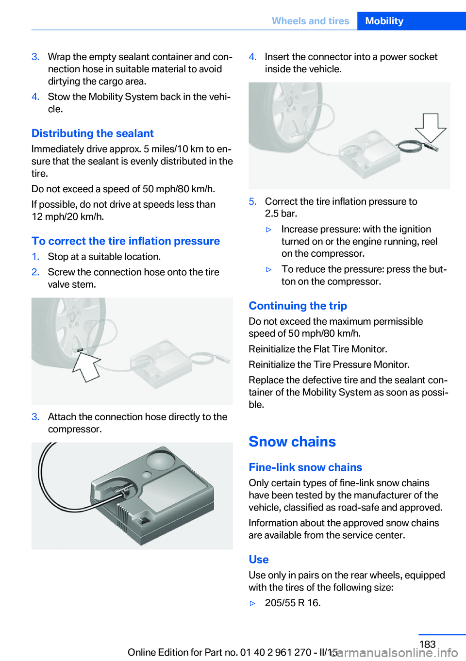
To correct the tire inflation pressure
1.Stop at a suitable location.2.Screw the connection hose onto the tire
valve stem.3.Attach the connection hose directly to the
compressor.4.Insert the connector into a power socket
inside the vehicle.5.Correct the tire inflation pressure to
2.5 bar.▷Increase pressure: with the ignition
turned on or the engine running, reel
on the compressor.▷To reduce the pressure: press the but‐
ton on the compressor.
Continuing the trip
Do not exceed the maximum permissible
speed of 50 mph/80 km/h.
Reinitialize the Flat Tire Monitor.
Reinitialize the Tire Pressure Monitor.
Replace the defective tire and the sealant con‐
tainer of the Mobility System as soon as possi‐
ble.
Snow chains Fine-link snow chains
Only certain types of fine-link snow chains
have been tested by the manufacturer of the
vehicle, classified as road-safe and approved.
Information about the approved snow chains
are available from the service center.
Use
Use only in pairs on the rear wheels, equipped
with the tires of the following size:
▷205/55 R 16.Seite 183Wheels and tiresMobility183
Online Edition for Part no. 01 40 2 961 270 - II/15
Page 188 of 232

▷205/50 R 17.▷225/45 R 17.
Follow the snow chain manufacturer's instruc‐
tions.
Make sure that the snow chains are always
sufficiently tight. Retighten as needed accord‐
ing to the chain manufacturer's instructions.
Do not initialize the Flat Tire Monitor after
mounting snow chains, as doing so may result
in incorrect readings.
Do not initialize the Tire Pressure Monitor after
mounting snow chains, as doing so may result
in incorrect readings.
When driving with snow chains, briefly activate
Dynamic Traction Control if needed.
Maximum speed with snow chains Do not exceed a speed of 30 mph/50 km/hwhen using snow chains.
Seite 184MobilityWheels and tires184
Online Edition for Part no. 01 40 2 961 270 - II/15
Page 191 of 232

Engine oilVehicle features and options
This chapter describes all standard, country-
specific and optional features offered with the
series. It also describes features that are not
necessarily available in your car, e. g., due to
the selected options or country versions. This
also applies to safety-related functions and
systems. The respectively applicable country
provisions must be observed when using the
respective features and systems.
General information The engine oil consumption is dependent on
the driving style and driving conditions.
The engine oil consumption can increase in
case of, for example:▷Sporty driving.▷Break-in the engine.▷Idling of the engine.▷Usage of non-approved engine oil grades.
Therefore, regularly check the engine oil level
after refueling.
The vehicle is equipped with electronic oil
measurement.
The electronic oil measurement has two meas‐
uring principles:
▷Status display▷Detailed measurement
Electronic oil measurement
Status display
The concept
The engine oil level is monitored electronically
while driving and shown on the Control Dis‐
play.
If the engine oil level reaches the minimum
level, a check control message is displayed.
Requirements
A current measured value is available after ap‐
prox. 30 minutes of driving. During a shorter
trip, the status of the last, sufficiently long trip
is displayed.
With frequent short-distance trips, regularly
perform a detailed measurement.
Displaying the engine oil level1."Vehicle info"2."Vehicle status"3. "Engine oil level"
Engine oil level display messages
Different messages appear on the display de‐
pending on the engine oil level. Pay attention
to these messages.
If the engine oil level is too low, within the next
125 miles/200 km Add engine oil, refer to
page 188.
Engine oil level too low
Add engine oil immediately; otherwise,
an insufficient amount of engine oil could re‐
sult in engine damage.◀
Take care not to add too much engine oil. Too much engine oil
Have the vehicle checked immediately;
otherwise, surplus engine oil can lead to en‐
gine damage.◀
Detailed measurement
The concept In the detailed measurement the engine oil
level is checked and displayed via a scale.
Seite 187Engine oilMobility187
Online Edition for Part no. 01 40 2 961 270 - II/15
Page 193 of 232

The engine oil quality is critical for the life of
the engine.
Suitable engine oil types
You can add engine oils that meet the follow‐
ing oil rating standards:Gasoline engineBMW Longlife-01.BMW Longlife-01 FE.
Further information regarding the oil specifica‐
tions and viscosities of engine oils can be in‐
quired with the service center.
Alternative engine oil types If an engine oil suitable for continuous use is
not available, up to 1 US quart/liter of an en‐
gine oil with the following oil rating can be
added:
Gasoline engineAPI SM or superior oil rating.
Engine oil change:
The vehicle manufacturer recommends that
you let the service center change the motor oil.
Seite 189Engine oilMobility189
Online Edition for Part no. 01 40 2 961 270 - II/15
Page 194 of 232

CoolantVehicle features and optionsThis chapter describes all standard, country-
specific and optional features offered with the
series. It also describes features that are not
necessarily available in your car, e. g., due to
the selected options or country versions. This
also applies to safety-related functions and
systems. The respectively applicable country
provisions must be observed when using the
respective features and systems.
Hints Danger of burns from hot engine
Do not open the cooling system while
the engine is hot; otherwise, esliding coolant
may cause burns.◀
Suitable additives
Only use suitable additives; otherwise,
engine damage may occur. The additives are
harmful to your health.◀
Coolant consists of water and additives.
Not all commercially available additives are
suitable for the vehicle. Information about the
suitable additives are available from the service
center.
Coolant level
General information
Depending on the engine installation, the cool‐
ant reservoir is located on the right side or the
left side of the engine compartment.
Checking1.Let the engine cool.2.The coolant level is correct if it lies be‐
tween the minimum and maximum marks.The marks are on the side of the coolant
reservoir.SymbolMeaningMaximumMinimum
Adding
1.Let the engine cool.2.Turn the lid of the coolant reservoir slightly
counterclockwise to allow any excess
pressure to dissipate, then open it.3.If the coolant is low, slowly add coolant up
to the specified level; do not overfill.4.Turn the lid until there is an audible click.
The arrows on the coolant reservoir and
the lid must point towards one another.5.Have the cause of the coolant loss elimi‐
nated as soon as possible.
Disposal
Comply with the relevant environmen‐
tal protection regulations when dispos‐
ing of coolant and coolant additives.
Seite 190MobilityCoolant190
Online Edition for Part no. 01 40 2 961 270 - II/15
Page 198 of 232

Danger of burns
Only change bulbs when they are cool;
otherwise, there is a danger of getting
burned.◀
Working on the lighting system
When working on the lighting system,
you should always reel off the lights affected to
prevent short circuits.
To avoid possible injury or equipment damage
when replacing bulbs, observe any instructions
provided by the bulb manufacturer.◀
Do not perform work/bulb replacement
on xenon headlights
Have any work on the xenon lighting system,
including bulb replacement, performed only by
a service center. Due to the high voltage
present in the system, there is a danger of fatal
injuries if work is carried out improperly.◀
Do not touch the bulbs
Do not touch the glass of new bulbs with
your bare hands, as even minute amounts of
contamination will burn into the bulb's surface
and reduce its service life.
Use a clean tissue, cloth or something similar,
or hold the bulb by its base.◀
Light-emitting diodes (LEDs)
Some items of equipment use light-emitting
diodes installed behind a cover as a light
source.
These light-emitting diodes, which are related
to conventional lasers, are officially designated as Class 1 light-emitting diodes.
Do not remove the covers
Do not remove the covers, and never
stare into the unfiltered light for several hours;
otherwise, irritation of the retina could result.◀Headlight glass
Condensation can form on the inside of the ex‐
ternal lights in cool or humid weather. When
driving with the light switched on, the conden‐
sation evaporates after a short time. The head‐
light glass does not need to be changed.
If the headlights do not dim despite driving
with the light switched on, increasing humidity
forms, e. g. water droplets in the light, have the service center check this.
Headlight setting The headlight adjustments can be affected by
changing lights and bulbs. Have the head‐
lights' settings checked and corrected by serv‐
ice after a replacement.
Front lights, bulb replacement
Halogen headlights
Overview1Daytime running lights/high beams/head‐
light flasher2Parking lights3Low beams4Turn signalSeite 194MobilityReplacing components194
Online Edition for Part no. 01 40 2 961 270 - II/15
Page 199 of 232

Accessing the turn signals and low beams
Follow general instructions, refer to page 193.1.In the wheel house, loosen the two brack‐
ets and remove the cover.
Turn signal
21-watt bulb, PY21W
1.If necessary, pull the inside trim of the
wheel house slightly inward. Turn the bulb
socket counterclockwise and remove.2.Press the bulb gently into the socket, turn
counterclockwise and remove.3.Install the new bulb and bulb holder in re‐
verse order of removal.4.Attach the cover to the wheel house.Low beams
55-watt bulb, H7.1.Turn the cover counterclockwise and re‐
move.2.Tilt the bulb down and then up to loosen it
from the holder and remove.3.Pull the connector off the bulb.4.Attach the connector to the new bulb.5.First insert the bulb at the top with the
strap, arrow 1, and then press down firmly,
arrow 2. The bulb must audibly latch in
place.6.Close the headlight housing with the lid.
Make sure that the lid engages.7.Attach the cover to the wheel house.Seite 195Replacing componentsMobility195
Online Edition for Part no. 01 40 2 961 270 - II/15