change time BMW 3 SERIES 1983 E30 User Guide
[x] Cancel search | Manufacturer: BMW, Model Year: 1983, Model line: 3 SERIES, Model: BMW 3 SERIES 1983 E30Pages: 228, PDF Size: 7.04 MB
Page 74 of 228
3When examining the bearings, remove
them from the engine block, the main bearing
caps, the connecting rods and the rod caps,
and lay them out on a clean surface in the
same general position as their location in the
engine. This will enable you to match any
bearing problems with the corresponding
crankshaft journal.
4Dirt and other foreign particles get into the
engine in a variety of ways. It may be left in
the engine during assembly, or it may pass
through filters or the crankcase ventilation
(PCV) system. It may get into the oil, and from
there into the bearings. Metal chips from
machining operations and normal engine wear
are often present. Abrasives are sometimes
left in engine components after recondi-
tioning, especially when parts are not
thoroughly cleaned using the proper cleaning
methods. Whatever the source, these foreign
objects often end up embedded in the soft
bearing material, and are easily recognised.
Large particles will not embed in the bearing,
and will score or gouge the bearing and
journal. The best prevention for this cause of
bearing failure is to clean all parts thoroughly,
and to keep everything spotlessly-clean
during engine assembly. Frequent and regular
engine oil and filter changes are also
recommended.
5Lack of lubrication (or lubrication
breakdown) has a number of interrelated
causes. Excessive heat (which thins the oil),
overloading (which squeezes the oil from the
bearing face) and oil “leakage” or “throw off”
(from excessive bearing clearances, worn oil
pump, or high engine speeds) all contribute to
lubrication breakdown. Blocked oil passages,
which usually are the result of misaligned oil
holes in a bearing shell, will also oil-starve a
bearing and destroy it. When lack of
lubrication is the cause of bearing failure, the
bearing material is wiped or extruded from the
steel backing of the bearing. Temperatures
may increase to the point where the steel
backing turns blue from overheating.
6Driving habits can have a definite effect on
bearing life. Full-throttle, low-speed operation
(labouring the engine) puts very high loads onbearings, which tends to squeeze out the oil
film. These loads cause the bearings to flex,
which produces fine cracks in the bearing
face (fatigue failure). Eventually, the bearing
material will loosen in places, and tear away
from the steel backing. Short-trip driving
leads to corrosion of bearings, because
insufficient engine heat is produced to drive
off the condensation and corrosive gases.
These products collect in the engine oil,
forming acid and sludge. As the oil is carried
to the engine bearings, the acid attacks and
corrodes the bearing material.
7Incorrect bearing refitting during engine
assembly will lead to bearing failure as well.
Tight-fitting bearings leave insufficient bearing
oil clearance, and will result in oil starvation.
Dirt or foreign particles trapped behind a
bearing shell result in high spots on the
bearing, which will lead to failure.
21 Engine overhaul-
reassembly sequence
1Before beginning engine reassembly, make
sure you have all the necessary new parts,
gaskets and seals, as well as the following
items on hand:
Common hand tools
A torque wrench
Piston ring refitting tool
Piston ring compressor
Vibration damper refitting tool
Short lengths of rubber or plastic hose to fit
over connecting rod bolts (where
applicable)
Plastigage
Feeler gauges
A fine-tooth file
New engine oil
Engine assembly oil or molybdenum
disulphide (“moly”) grease
Gasket sealant
Thread-locking compound
2In order to save time and avoid problems,
engine reassembly should be done in the
following general order:Piston rings
Crankshaft and main bearings
Piston/connecting rod assemblies
Oil pump
Sump
Cylinder head assembly
Timing belt or chain and tensioner
assemblies
Water pump
Timing belt or chain covers
Intake and exhaust manifolds
Valve cover
Engine rear plate
Flywheel/driveplate
22 Piston rings- refitting
2
1Before fitting the new piston rings, the ring
end gaps must be checked. It’s assumed that
the piston ring side clearance has been
checked and verified (see Section 18).
2Lay out the piston/connecting rod
assemblies and the new ring sets, so that the
ring sets will be matched with the same piston
and cylinder during the end gap measurement
and engine assembly.
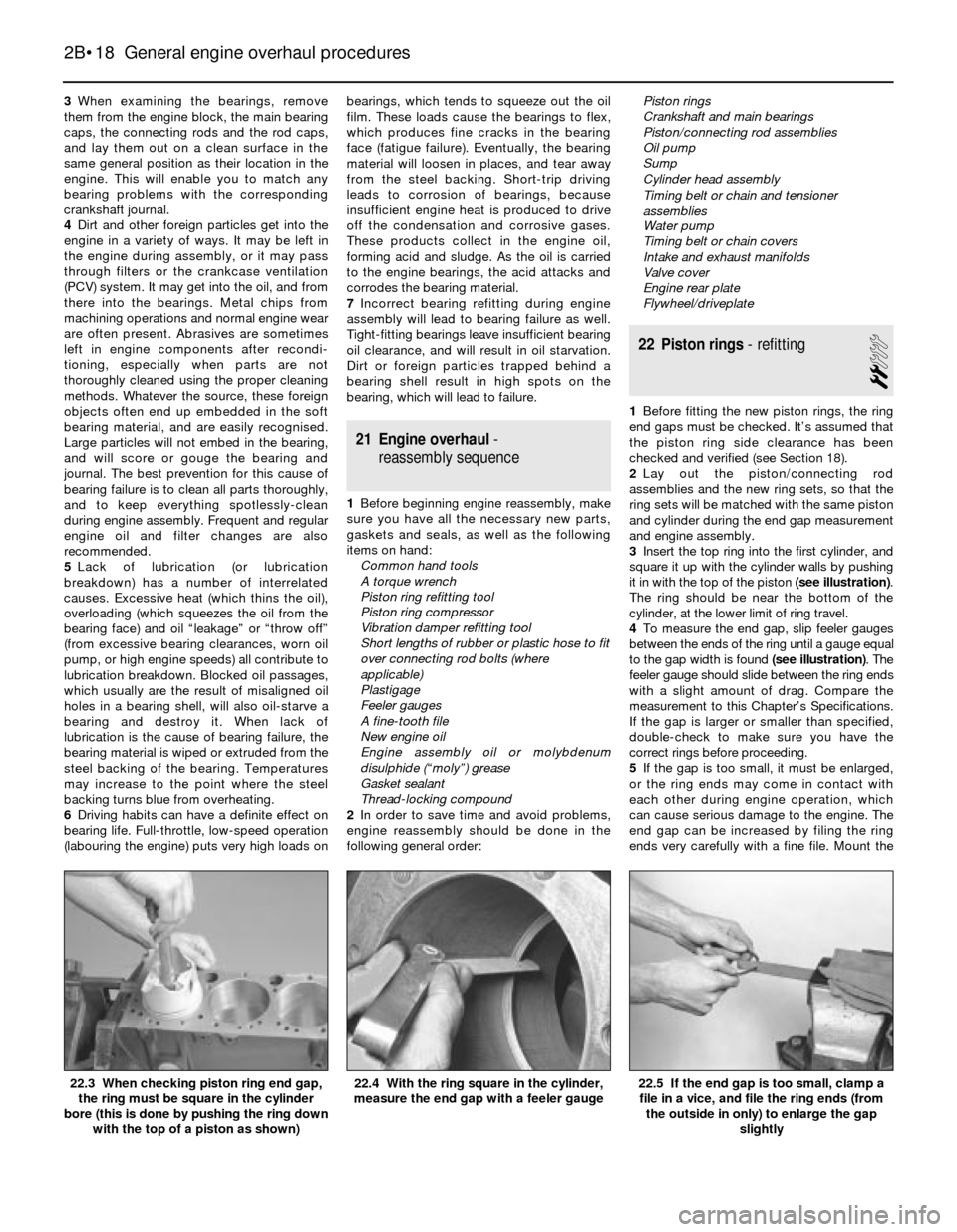
3Insert the top ring into the first cylinder, and
square it up with the cylinder walls by pushing
it in with the top of the piston (see illustration).
The ring should be near the bottom of the
cylinder, at the lower limit of ring travel.
4To measure the end gap, slip feeler gauges
between the ends of the ring until a gauge equal
to the gap width is found(see illustration). The
feeler gauge should slide between the ring ends
with a slight amount of drag. Compare the
measurement to this Chapter’s Specifications.
If the gap is larger or smaller than specified,
double-check to make sure you have the
correct rings before proceeding.
5If the gap is too small, it must be enlarged,
or the ring ends may come in contact with
each other during engine operation, which
can cause serious damage to the engine. The
end gap can be increased by filing the ring
ends very carefully with a fine file. Mount the
2B•18 General engine overhaul procedures
22.5 If the end gap is too small, clamp a
file in a vice, and file the ring ends (from
the outside in only) to enlarge the gap
slightly22.4 With the ring square in the cylinder,
measure the end gap with a feeler gauge22.3 When checking piston ring end gap,
the ring must be square in the cylinder
bore (this is done by pushing the ring down
with the top of a piston as shown)
Page 78 of 228
the bearing - use your fingernail or the edge of
a credit card.
20Make sure the bearing faces are perfectly
clean, then apply a uniform layer of
molybdenum disulphide (“moly”) grease or
engine assembly oil to both of them. You’ll
have to push the piston into the cylinder to
expose the face of the bearing shell in the
connecting rod - be sure to slip the protective
hoses over the rod bolts first, where
applicable.
21Slide the connecting rod back into place
on the journal, and remove the protective
hoses from the rod cap bolts. Refit the rod
cap, and tighten the nuts/bolts to the
specified torque.
22Repeat the entire procedure for the
remaining pistons/connecting rods.
23The important points to remember are:
a) Keep the back sides of the bearing shells
and the insides of the connecting rods
and caps perfectly clean when
assembling them.
b) Make sure you have the correct
piston/rod assembly for each cylinder.
c) The notch or mark on the piston must
face the front of the engine.
d) Lubricate the cylinder walls with clean oil.
e) Lubricate the bearing faces when refitting
the rod caps after the oil clearance has
been checked.
24After all the piston/connecting rod
assemblies have been properly fitted, rotate
the crankshaft a number of times by hand to
check for any obvious binding.25Check the connecting rod side play (see
Section 13).
26Compare the measured side play to the
Specifications to make sure it’s correct. If it
was correct before dismantling, and the
original crankshaft and rods were refitted, it
should still be right. If new rods or a new
crankshaft were fitted, the side play may be
incorrect. If so, the rods will have to be
removed and taken to a machine shop for
attention.
27 Initial start-up and running-
in after overhaul
1
Warning:Have a fire extinguisher
handy when starting the engine
for the first time.
1Once the engine has been refitted in the
vehicle, double-check the engine oil and
coolant levels.
2With the spark plugs removed and the
ignition system disabled (see Section 3), crank
the engine until oil pressure registers on the
gauge, or until the oil pressure warning light
goes out.
3Refit the spark plugs, connect the HT leads,
and restore the ignition system functions (see
Section 3).
4Start the engine. It may take a few
moments for the fuel system to build uppressure, but the engine should start without
a great deal of effort. Note: If backfiring
occurs through the throttle body or
carburettor, check the valve timing (check that
the timing chain/belt has been correctly fitted),
the firing order (check the fitted order of the
spark plug HT leads), and the ignition timing.
5After the engine starts, it should be allowed
to warm up to normal operating temperature.
While the engine is warming up, make a
thorough check for fuel, oil and coolant leaks.
6Shut the engine off and recheck the engine
oil and coolant levels.
7Drive the vehicle to an area with minimum
traffic, accelerate at full throttle from 30 to
50 mph, then lift off the throttle completely,
and allow the vehicle to slow to 30 mph with
the throttle closed. Repeat the procedure
10 or 12 times. This will load the piston rings,
and cause them to seat properly against the
cylinder walls. Check again for oil and coolant
leaks.
8Drive the vehicle gently for the first
500 miles (no sustained high speeds) and
keep a constant check on the oil level. It is not
unusual for an engine to use oil during the
running-in period.
9At approximately 500 to 600 miles, change
the oil and filter.
10For the next few hundred miles, drive the
vehicle normally - don’t nurse it, but don’t
abuse it, either.
11After 2000 miles, change the oil and filter
again. The engine may now be considered to
be fully run-in.
2B•22 General engine overhaul procedures
Page 102 of 228
Throttle positioner (2BE)
24Special tools are required to carry out a
comprehensive adjustment on the 2BE
carburettor. This work should therefore be left
to a BMW dealer.
13 Fuel injection -
general information
The fuel injection system is composed of
three basic sub-systems: fuel system, air
intake system and electronic control system.
Fuel system
An electric fuel pump, located inside the
fuel tank or beside the fuel tank, supplies fuel
under constant pressure to the fuel rail, which
distributes fuel evenly to all injectors. From
the fuel rail, fuel is injected into the intake
ports, just above the intake valves, by the fuel
injectors. The amount of fuel supplied by the
injectors is precisely controlled by an
Electronic Control Unit (ECU). An additional
injector, known as the cold start injector (L-
Jetronic and early Motronic systems only),
supplies extra fuel into the intake manifold for
starting. A pressure regulator controls system
pressure in relation to intake manifold
vacuum. A fuel filter between the fuel pump
and the fuel rail filters the fuel, to protect the
components of the system.
Air intake system
The air intake system consists of an air filter
housing, an airflow meter, a throttle body, the
intake manifold, and the associated ducting.
The airflow meter is an information-gathering
device for the ECU. These models are
equipped with the vane-type airflow meter. A
potentiometer measures intake airflow, and a
temperature sensor measures intake air
temperature. This information helps the ECU
determine the amount of fuel to be injected by
the injectors (injection duration). The throttle
plate inside the throttle body is controlled by
the driver. As the throttle plate opens, the
amount of air that can pass through the
system increases, so the potentiometer opens
further and the ECU signals the injectors to
increase the amount of fuel delivered to the
intake ports.
Electronic control system
The computer control system controls the
fuel system and other systems by means of
an Electronic Control Unit (ECU). The ECU
receives signals from a number of information
sensors which monitor such variables as
intake air volume, intake air temperature,
coolant temperature, engine rpm,
acceleration/deceleration, and exhaust
oxygen content. These signals help the ECU
determine the injection duration necessary for
the optimum air/fuel ratio. These sensors and
their corresponding ECU-controlled outputactuators are located throughout the engine
compartment. For further information
regarding the ECU and its relationship to the
engine electrical systems and ignition system,
refer to Chapters 5 and 6.
Either an L-Jetronic system or a Motronic
system is fitted. Later models have an
updated version of the original Motronic
system.
14 Fuel injection systems
L-Jetronic fuel injection system
The Bosch L-Jetronic fuel injection system
is used on most 3-Series models up to 1987,
and on most E28 (“old-shape”) 5-Series
models. It is an electronically-controlled fuel
injection system that utilises one solenoid-
operated fuel injector per cylinder. The system
is governed by an Electronic Control Unit
(ECU) which processes information sent by
various sensors, and in turn precisely
meters the fuel to the cylinders by
adjusting the amount of time that the injectors
are open.
An electric fuel pump delivers fuel under
high pressure to the injectors, through the fuel
feed line and an in-line filter. A pressure
regulator keeps fuel available at an optimum
pressure, allowing pressure to rise or fall
depending on engine speed and load. Any
excess fuel is returned to the fuel tank by a
separate line.
A sensor in the air intake duct constantly
measures the mass of the incoming air, and
the ECU adjusts the fuel mixture to provide an
optimum air/fuel ratio.
Other components incorporated in the
system are the throttle valve (which controls
airflow to the engine), the coolant temperature
sensor, the throttle position switch, idle
stabiliser valve (which bypasses air around
the throttle plate to control idle speed) and
associated relays and fuses.
Motronic fuel injection system
The Motronic system combines the fuel
control of the L-Jetronic fuel injection system
with the control of ignition timing, idle speed
and emissions into one control unit.
The fuel injection and idle speed control
functions are similar to those used on the L-
Jetronic system described above. For more
information on the Motronic system, see
Chapter 6.
An oxygen sensor is mounted in the
exhaust system on later models with a
catalytic converter. This sensor continually
reads the oxygen content of the exhaust gas.
The information is used by the ECU to adjust
the duration of injection, making it possible to
adjust the fuel mixture for optimum converter
efficiency and minimum emissions.
15 Fuel injection system-
check
2
Warning: Fuel is extremely
flammable, so take extra
precautions when you work on
any part of the fuel system. Don’t
smoke, or allow open flames or bare light
bulbs, near the work area. Don’t work in a
garage where a natural gas-type appliance
(such as a water heater or clothes dryer)
with a pilot light is present. If you spill any
fuel on your skin, rinse it off immediately
with soap and water. When you perform
any kind of work on the fuel system, wear
safety glasses, and have a fire
extinguisher on hand.
1Check the earth wire connections. Check
all wiring harness connectors that are related
to the system. Loose connectors and poor
earths can cause many problems that
resemble more serious malfunctions.
2Make sure the battery is fully charged, as
the control unit and sensors depend on an
accurate supply voltage in order to properly
meter the fuel.
3Check the air filter element - a dirty or
partially-blocked filter will severely impede
performance and economy (see Chapter 1).
4If a blown fuse is found, renew it and see if
it blows again. If it does, search for an earthed
wire in the harness related to the system.
5Check the air intake duct from the airflow
meter to the intake manifold for leaks. Intake
air leaks can cause a variety of problems. Also
check the condition of the vacuum hoses
connected to the intake manifold.
6Remove the air intake duct from the throttle
body, and check for dirt, carbon and other
residue build-up. If it’s dirty, clean it with
carburettor cleaner and a toothbrush.
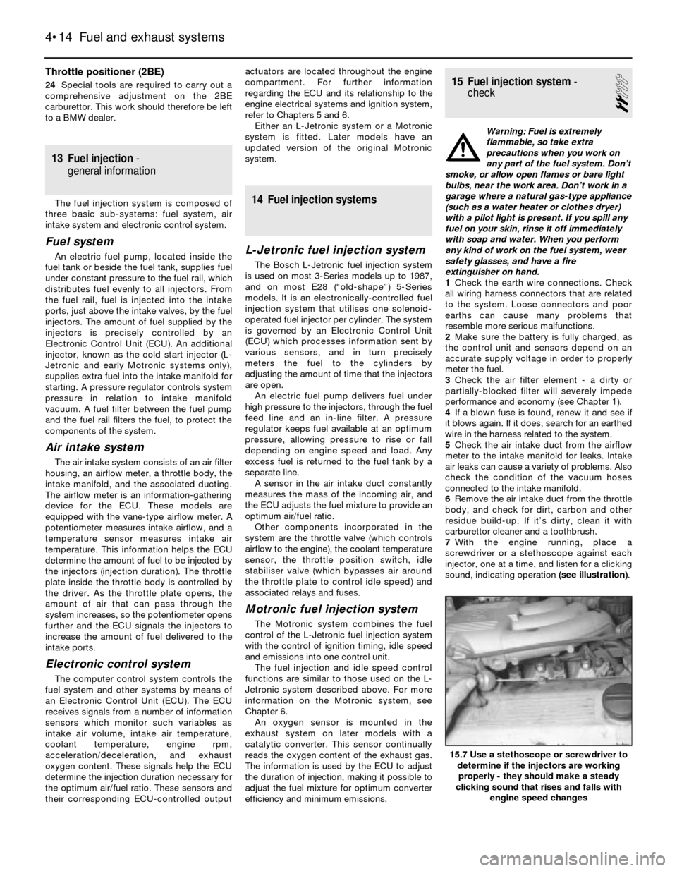
7With the engine running, place a
screwdriver or a stethoscope against each
injector, one at a time, and listen for a clicking
sound, indicating operation (see illustration).
4•14 Fuel and exhaust systems
15.7 Use a stethoscope or screwdriver to
determine if the injectors are working
properly - they should make a steady
clicking sound that rises and falls with
engine speed changes
Page 113 of 228
5 Ignition system- general
information and precautions
The ignition system includes the ignition
switch, the battery, the distributor, the primary
(low-voltage/low-tension or LT) and
secondary (high-voltage/high-tension or HT)
wiring circuits, the spark plugs and the spark
plug leads. Models fitted with a carburettor or
L-Jetronic fuel injection are equipped with a
Transistorised Coil Ignition (TCI) system.
Models fitted with the Motronic fuel injection
system have the ignition system incorporated
within the Motronic system (Digital Motor
Electronics or DME).
Transistorised Coil Ignition (TCI)
system
This system is has four major components;
the impulse generator, the ignition control
unit, the coil, and the spark plugs. The
impulse generator provides a timing signal for
the ignition system. Equivalent to cam-
actuated breaker points in a standard
distributor, the impulse generator creates an
A/C voltage signal every time the trigger
wheel tabs pass the impulse generator tabs.
When the ignition control unit (capacitive
discharge unit) receives the voltage signal, it
triggers a spark discharge from the coil by
interrupting the primary coil circuit. The
ignition dwell (coil charging time) is adjusted
by the ignition control unit for the most
intense spark. Note: The air gap (distance
between the impulse generator and trigger
wheel tabs) can be adjusted (see Section 11).
Ignition timing is mechanically adjusted
(see Section 7). A centrifugal advance unit
that consists of spring-loaded rotating
weights advances ignition timing as engine
speed increases. The vacuum advance
adjusts ignition timing to compensate for
changes in engine load.
Motronic ignition system
This system, also known as Digital Motor
Electronics (DME), incorporates all ignition
and fuel injection functions into one central
control unit or ECU (computer). The ignition
timing is based on inputs the ECU receives for
engine load, engine speed, coolant
temperature and intake air temperature. The
only function the distributor performs is the
distribution of the high voltage signal to the
individual spark plugs. The distributor is
attached directly to the cylinder head. There is
no mechanical spark advance system used on
these systems.
Ignition timing is electronically-controlled,
and is not adjustable on Motronic systems.
During starting, a crankshaft position sensor
(reference sensor) relays the crankshaft
position to the ECU, and an initial baseline
ignition point is determined. Once the engineis running, the ignition timing is continually
changing, based on the various input signals
to the ECU. Engine speed is signalled by a
speed sensor. Early Motronic systems have
the position reference sensor and the speed
sensor mounted on the bellhousing over the
flywheel on the left-hand side. Later Motronic
systems have a single sensor (pulse sensor)
mounted over the crankshaft pulley. This
sensor functions as a speed sensor as well as
a position reference sensor. Refer to Sec-
tion 12 for checking and renewing the ignition
sensors. Note: Some models are equipped
with a TDC sensor mounted on the front of the
engine. This sensor is strictly for the BMW
service test unit, and it is not part of the
Motronic ignition system.
Precautions
Certain precautions must be observed
when working on a transistorised ignition
system.
a) Do not disconnect the battery cables
when the engine is running
b) Make sure the ignition control unit (TCI
ignition system) is always well earthed
(see Section 10).
c) Keep water away from the distributor and
HT leads.
d) If a tachometer is to be connected to the
engine, always connect the tachometer
positive (+) lead to the ignition coil
negative terminal (-) and never to the
distributor.
e) Do not allow the coil terminals to be
earthed, as the impulse generator or coil
could be damaged.
f) Do not leave the ignition switch on for
more than ten minutes with the engine
off, or if the engine will not start.
6 Ignition system- check
2
Warning: Because of the high
voltage generated by the ignition
system, extreme care should be
taken whenever an operation is
performed involving ignition components.
This not only includes the impulse
generator (electronic ignition), coil,
distributor and spark plug HT leads, but
related components such as spark plug
connectors, tachometer and other test
equipment.
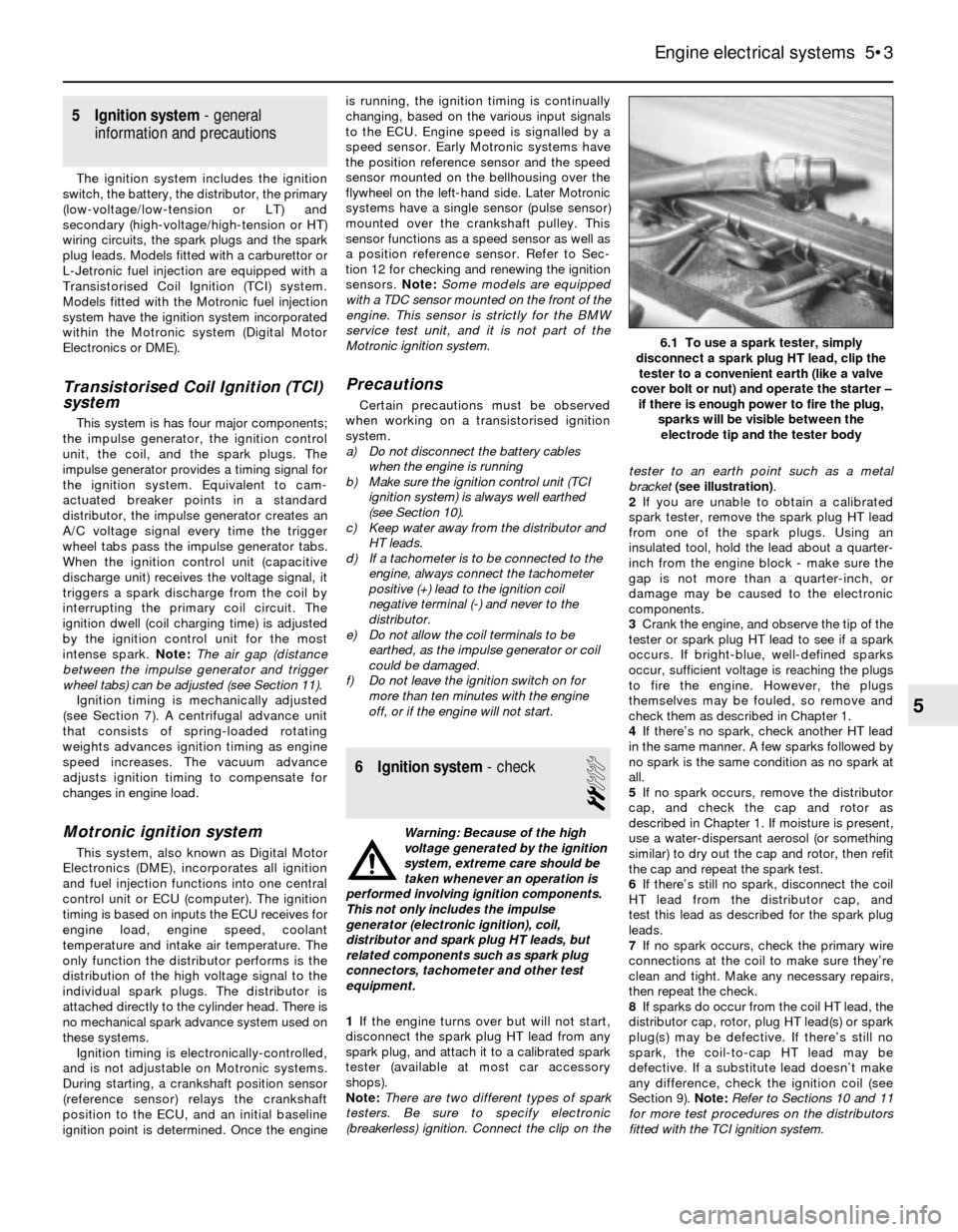
1If the engine turns over but will not start,
disconnect the spark plug HT lead from any
spark plug, and attach it to a calibrated spark
tester (available at most car accessory
shops).
Note:There are two different types of spark
testers. Be sure to specify electronic
(breakerless) ignition. Connect the clip on thetester to an earth point such as a metal
bracket (see illustration).
2If you are unable to obtain a calibrated
spark tester, remove the spark plug HT lead
from one of the spark plugs. Using an
insulated tool, hold the lead about a quarter-
inch from the engine block - make sure the
gap is not more than a quarter-inch, or
damage may be caused to the electronic
components.
3Crank the engine, and observe the tip of the
tester or spark plug HT lead to see if a spark
occurs. If bright-blue, well-defined sparks
occur, sufficient voltage is reaching the plugs
to fire the engine. However, the plugs
themselves may be fouled, so remove and
check them as described in Chapter 1.
4If there’s no spark, check another HT lead
in the same manner. A few sparks followed by
no spark is the same condition as no spark at
all.
5If no spark occurs, remove the distributor
cap, and check the cap and rotor as
described in Chapter 1. If moisture is present,
use a water-dispersant aerosol (or something
similar) to dry out the cap and rotor, then refit
the cap and repeat the spark test.
6If there’s still no spark, disconnect the coil
HT lead from the distributor cap, and
test this lead as described for the spark plug
leads.
7If no spark occurs, check the primary wire
connections at the coil to make sure they’re
clean and tight. Make any necessary repairs,
then repeat the check.
8If sparks do occur from the coil HT lead, the
distributor cap, rotor, plug HT lead(s) or spark
plug(s) may be defective. If there’s still no
spark, the coil-to-cap HT lead may be
defective. If a substitute lead doesn’t make
any difference, check the ignition coil (see
Section 9). Note:Refer to Sections 10 and 11
for more test procedures on the distributors
fitted with the TCI ignition system.
Engine electrical systems 5•3
6.1 To use a spark tester, simply
disconnect a spark plug HT lead, clip the
tester to a convenient earth (like a valve
cover bolt or nut) and operate the starter –
if there is enough power to fire the plug,
sparks will be visible between the
electrode tip and the tester body
5
Page 118 of 228
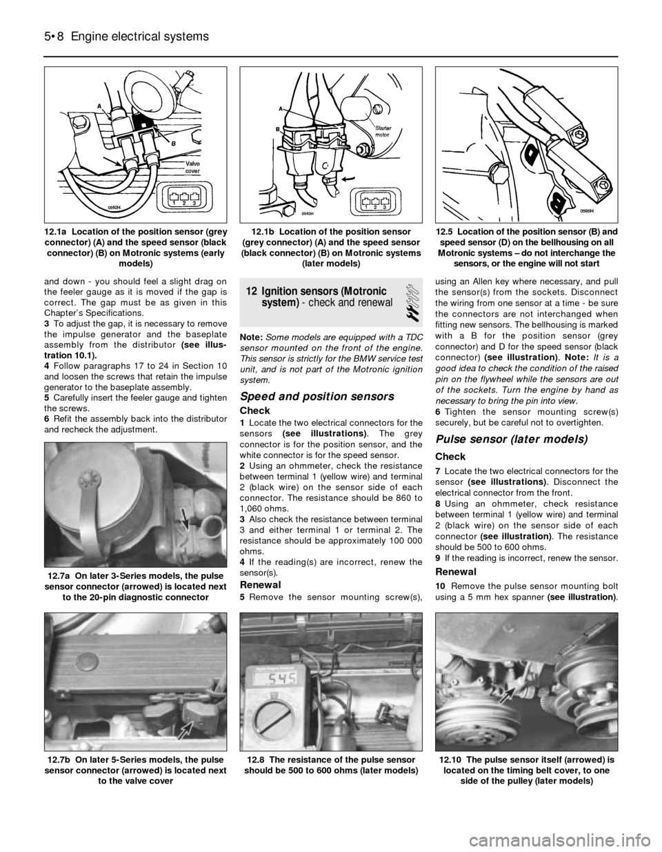
and down - you should feel a slight drag on
the feeler gauge as it is moved if the gap is
correct. The gap must be as given in this
Chapter’s Specifications.
3To adjust the gap, it is necessary to remove
the impulse generator and the baseplate
assembly from the distributor (see illus-
tration 10.1).
4Follow paragraphs 17 to 24 in Section 10
and loosen the screws that retain the impulse
generator to the baseplate assembly.
5Carefully insert the feeler gauge and tighten
the screws.
6Refit the assembly back into the distributor
and recheck the adjustment.12 Ignition sensors (Motronic
system)- check and renewal
2
Note:Some models are equipped with a TDC
sensor mounted on the front of the engine.
This sensor is strictly for the BMW service test
unit, and is not part of the Motronic ignition
system.
Speed and position sensors
Check
1Locate the two electrical connectors for the
sensors (see illustrations). The grey
connector is for the position sensor, and the
white connector is for the speed sensor.
2Using an ohmmeter, check the resistance
between terminal 1 (yellow wire) and terminal
2 (black wire) on the sensor side of each
connector. The resistance should be 860 to
1,060 ohms.
3Also check the resistance between terminal
3 and either terminal 1 or terminal 2. The
resistance should be approximately 100 000
ohms.
4If the reading(s) are incorrect, renew the
sensor(s).
Renewal
5Remove the sensor mounting screw(s),using an Allen key where necessary, and pull
the sensor(s) from the sockets. Disconnect
the wiring from one sensor at a time - be sure
the connectors are not interchanged when
fitting new sensors. The bellhousing is marked
with a B for the position sensor (grey
connector) and D for the speed sensor (black
connector) (see illustration). Note: It is a
good idea to check the condition of the raised
pin on the flywheel while the sensors are out
of the sockets. Turn the engine by hand as
necessary to bring the pin into view.
6Tighten the sensor mounting screw(s)
securely, but be careful not to overtighten.
Pulse sensor (later models)
Check
7Locate the two electrical connectors for the
sensor (see illustrations). Disconnect the
electrical connector from the front.
8Using an ohmmeter, check resistance
between terminal 1 (yellow wire) and terminal
2 (black wire) on the sensor side of each
connector (see illustration). The resistance
should be 500 to 600 ohms.
9If the reading is incorrect, renew the sensor.
Renewal
10Remove the pulse sensor mounting bolt
using a 5 mm hex spanner (see illustration).
5•8 Engine electrical systems
12.10 The pulse sensor itself (arrowed) is
located on the timing belt cover, to one
side of the pulley (later models)12.8 The resistance of the pulse sensor
should be 500 to 600 ohms (later models)12.7b On later 5-Series models, the pulse
sensor connector (arrowed) is located next
to the valve cover
12.7a On later 3-Series models, the pulse
sensor connector (arrowed) is located next
to the 20-pin diagnostic connector
12.5 Location of the position sensor (B) and
speed sensor (D) on the bellhousing on all
Motronic systems – do not interchange the
sensors, or the engine will not start12.1b Location of the position sensor
(grey connector) (A) and the speed sensor
(black connector) (B) on Motronic systems
(later models)12.1a Location of the position sensor (grey
connector) (A) and the speed sensor (black
connector) (B) on Motronic systems (early
models)
Page 124 of 228
4 Information sensors
2
Note:Refer to Chapters 4 and 5 for additional
information on the location and diagnosis of
the information sensors that are not covered in
this Section.
Coolant temperature sensor
General description
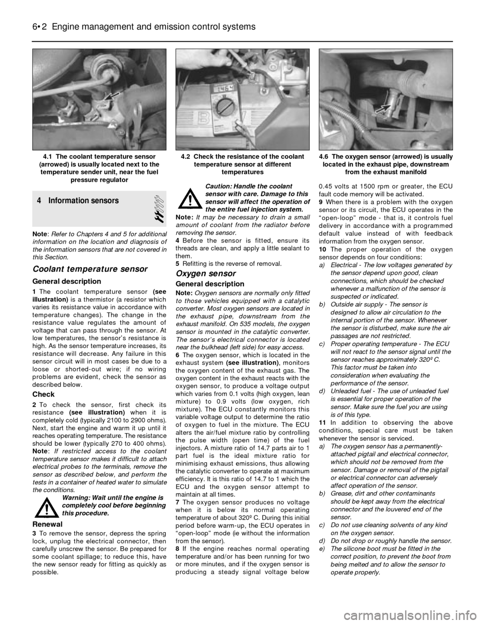
1The coolant temperature sensor (see
illustration)is a thermistor (a resistor which
varies its resistance value in accordance with
temperature changes). The change in the
resistance value regulates the amount of
voltage that can pass through the sensor. At
low temperatures, the sensor’s resistance is
high. As the sensor temperature increases, its
resistance will decrease. Any failure in this
sensor circuit will in most cases be due to a
loose or shorted-out wire; if no wiring
problems are evident, check the sensor as
described below.
Check
2To check the sensor, first check its
resistance (see illustration)when it is
completely cold (typically 2100 to 2900 ohms).
Next, start the engine and warm it up until it
reaches operating temperature. The resistance
should be lower (typically 270 to 400 ohms).
Note: If restricted access to the coolant
temperature sensor makes it difficult to attach
electrical probes to the terminals, remove the
sensor as described below, and perform the
tests in a container of heated water to simulate
the conditions.
Warning: Wait until the engine is
completely cool before beginning
this procedure.
Renewal
3To remove the sensor, depress the spring
lock, unplug the electrical connector, then
carefully unscrew the sensor. Be prepared for
some coolant spillage; to reduce this, have
the new sensor ready for fitting as quickly as
possible.Caution: Handle the coolant
sensor with care. Damage to this
sensor will affect the operation of
the entire fuel injection system.
Note: It may be necessary to drain a small
amount of coolant from the radiator before
removing the sensor.
4Before the sensor is fitted, ensure its
threads are clean, and apply a little sealant to
them.
5Refitting is the reverse of removal.
Oxygen sensor
General description
Note:Oxygen sensors are normally only fitted
to those vehicles equipped with a catalytic
converter. Most oxygen sensors are located in
the exhaust pipe, downstream from the
exhaust manifold. On 535 models, the oxygen
sensor is mounted in the catalytic converter.
The sensor’s electrical connector is located
near the bulkhead (left side) for easy access.
6The oxygen sensor, which is located in the
exhaust system (see illustration), monitors
the oxygen content of the exhaust gas. The
oxygen content in the exhaust reacts with the
oxygen sensor, to produce a voltage output
which varies from 0.1 volts (high oxygen, lean
mixture) to 0.9 volts (low oxygen, rich
mixture). The ECU constantly monitors this
variable voltage output to determine the ratio
of oxygen to fuel in the mixture. The ECU
alters the air/fuel mixture ratio by controlling
the pulse width (open time) of the fuel
injectors. A mixture ratio of 14.7 parts air to 1
part fuel is the ideal mixture ratio for
minimising exhaust emissions, thus allowing
the catalytic converter to operate at maximum
efficiency. It is this ratio of 14.7 to 1 which the
ECU and the oxygen sensor attempt to
maintain at all times.
7The oxygen sensor produces no voltage
when it is below its normal operating
temperature of about 320º C. During this initial
period before warm-up, the ECU operates in
“open-loop” mode (ie without the information
from the sensor).
8If the engine reaches normal operating
temperature and/or has been running for two
or more minutes, and if the oxygen sensor is
producing a steady signal voltage below 0.45 volts at 1500 rpm or greater, the ECU
fault code memory will be activated.
9When there is a problem with the oxygen
sensor or its circuit, the ECU operates in the
“open-loop” mode - that is, it controls fuel
delivery in accordance with a programmed
default value instead of with feedback
information from the oxygen sensor.
10The proper operation of the oxygen
sensor depends on four conditions:
a) Electrical - The low voltages generated by
the sensor depend upon good, clean
connections, which should be checked
whenever a malfunction of the sensor is
suspected or indicated.
b) Outside air supply - The sensor is
designed to allow air circulation to the
internal portion of the sensor. Whenever
the sensor is disturbed, make sure the air
passages are not restricted.
c) Proper operating temperature - The ECU
will not react to the sensor signal until the
sensor reaches approximately 320º C.
This factor must be taken into
consideration when evaluating the
performance of the sensor.
d) Unleaded fuel - The use of unleaded fuel
is essential for proper operation of the
sensor. Make sure the fuel you are using
is of this type.
11In addition to observing the above
conditions, special care must be taken
whenever the sensor is serviced.
a) The oxygen sensor has a permanently-
attached pigtail and electrical connector,
which should not be removed from the
sensor. Damage or removal of the pigtail
or electrical connector can adversely
affect operation of the sensor.
b) Grease, dirt and other contaminants
should be kept away from the electrical
connector and the louvered end of the
sensor.
c) Do not use cleaning solvents of any kind
on the oxygen sensor.
d) Do not drop or roughly handle the sensor.
e) The silicone boot must be fitted in the
correct position, to prevent the boot from
being melted and to allow the sensor to
operate properly.
6•2 Engine management and emission control systems
4.6 The oxygen sensor (arrowed) is usually
located in the exhaust pipe, downstream
from the exhaust manifold4.2 Check the resistance of the coolant
temperature sensor at different
temperatures4.1 The coolant temperature sensor
(arrowed) is usually located next to the
temperature sender unit, near the fuel
pressure regulator
Page 130 of 228
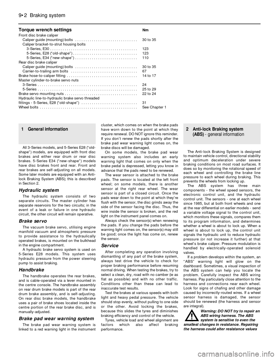
Torque wrench settingsNm
Front disc brake caliper
Caliper guide (mounting) bolts . . . . . . . . . . . . . . . . . . . . . . . . . . . . . . 30 to 35
Caliper bracket-to-strut housing bolts
3-Series, E30 . . . . . . . . . . . . . . . . . . . . . . . . . . . . . . . . . . . . . . . . . . 123
5-Series, E28 (“old-shape”) . . . . . . . . . . . . . . . . . . . . . . . . . . . . . . . 123
5-Series, E34 (“new-shape”) . . . . . . . . . . . . . . . . . . . . . . . . . . . . . . 110
Rear disc brake caliper
Caliper guide (mounting) bolts . . . . . . . . . . . . . . . . . . . . . . . . . . . . . . 30 to 35
Carrier-to-trailing arm bolts . . . . . . . . . . . . . . . . . . . . . . . . . . . . . . . . 67
Brake hose-to-caliper fitting . . . . . . . . . . . . . . . . . . . . . . . . . . . . . . . . . . 14 to 17
Master cylinder-to-brake servo nuts
3-Series . . . . . . . . . . . . . . . . . . . . . . . . . . . . . . . . . . . . . . . . . . . . . . . . 24
5-Series . . . . . . . . . . . . . . . . . . . . . . . . . . . . . . . . . . . . . . . . . . . . . . . . 25 to 29
Brake servo mounting nuts . . . . . . . . . . . . . . . . . . . . . . . . . . . . . . . . . . . 22 to 24
Hydraulic line-to-hydraulic brake servo threaded
fittings - 5-Series, E28 (“old-shape”) . . . . . . . . . . . . . . . . . . . . . . . . . . . 31
Wheel bolts . . . . . . . . . . . . . . . . . . . . . . . . . . . . . . . . . . . . . . . . . . . . . . . See Chapter 1
9•2 Braking system
1 General information
All 3-Series models, and 5-Series E28 (“old-
shape”) models, are equipped with front disc
brakes and either rear drum or rear disc
brakes. 5-Series E34 (“new-shape”) models
have disc brakes front and rear. Front and
rear brakes are self-adjusting on all models.
Some later models are equipped with an Anti-
lock Braking System (ABS); this is described
in Section 2.
Hydraulic system
The hydraulic system consists of two
separate circuits. The master cylinder has
separate reservoirs for the two circuits; in the
event of a leak or failure in one hydraulic
circuit, the other circuit will remain operative.
Brake servo
The vacuum brake servo, utilising engine
manifold vacuum and atmospheric pressure
to provide assistance to the hydraulically
operated brakes, is mounted on the bulkhead
in the engine compartment.
A hydraulic brake servo system is used on
5-Series E28 models. This system uses
hydraulic pressure from the power steering
pump to assist braking.
Handbrake
The handbrake operates the rear brakes,
and is cable-operated via a lever mounted in
the centre console. The handbrake assembly
on rear drum brake models is part of the rear
drum brake assembly, and is self-adjusting.
On rear disc brake models, the handbrake
uses a pair of brake shoes located inside the
centre portion of the rear brake disc, and is
manually-adjusted.
Brake pad wear warning system
The brake pad wear warning system is
linked to a red warning light in the instrumentcluster, which comes on when the brake pads
have worn down to the point at which they
require renewal. DO NOT ignore this reminder.
If you don’t renew the pads shortly after the
brake pad wear warning light comes on, the
brake discs will be damaged.
On some models, the brake pad wear
warning system also includes an early
warning light that comes on only when the
brake pedal is depressed, letting you know in
advance that the pads need to be renewed.
The wear sensor is attached to the brake
pads. The sensor is located at the left front
wheel; on some models, there is another
sensor at the right rear wheel. The wear
sensor is part of a closed circuit. Once the
pads wear down to the point at which they’re
flush with the sensor, the disc grinds away the
side of the sensor facing the disc. Thus, the
wire inside the sensor is broken, and the red
light on the instrument panel comes on.
Always check the sensor(s) when renewing
the pads. If you change the pads before the
warning light comes on, the sensor(s) may still
be good; once the light has come on, renew
the sensor.
Service
After completing any operation involving
dismantling of any part of the brake system,
always test drive the vehicle to check for
proper braking performance before resuming
normal driving. When testing the brakes, try to
select a clean, dry, road with no camber (ie as
flat as possible) and with no other traffic.
Conditions other than these can lead to
inaccurate test results.
Test the brakes at various speeds with both
light and heavy pedal pressure. The vehicle
should stop evenly, without pulling to one side
or the other. Avoid locking the brakes,
because this slides the tyres and diminishes
braking efficiency and control of the vehicle.
Tyres, vehicle load and wheel alignment are
factors which also affect braking
performance.
2 Anti-lock Braking system
(ABS)- general information
The Anti-lock Braking System is designed
to maintain vehicle control, directional stability
and optimum deceleration under severe
braking conditions on most road surfaces. It
does so by monitoring the rotational speed of
each wheel and controlling the brake line
pressure to each wheel during braking. This
prevents the wheels from locking up.
The ABS system has three main
components - the wheel speed sensors, the
electronic control unit, and the hydraulic
control unit. The sensors - one at each wheel
since 1985, but at both front wheels and one
at the rear differential on earlier models - send
a variable voltage signal to the control unit,
which monitors these signals, compares them
to its program information, and determines
whether a wheel is about to lock up. When a
wheel is about to lock up, the control unit
signals the hydraulic unit to reduce hydraulic
pressure (or not increase it further) at that
wheel’s brake caliper. Pressure modulation is
handled by electrically-operated solenoid
valves.
If a problem develops within the system, an
“ABS” warning light will glow on the
dashboard. Sometimes, a visual inspection of
the ABS system can help you locate the
problem. Carefully inspect the ABS wiring
harness. Pay particularly close attention to the
harness and connections near each wheel.
Look for signs of chafing and other damage
caused by incorrectly-routed wires. If a wheel
sensor harness is damaged, the sensor
should be renewed (the harness and sensor
are integral).
Warning: DO NOT try to repair an
ABS wiring harness. The ABS
system is sensitive to even the
smallest changes in resistance. Repairing
the harness could alter resistance values
Page 132 of 228
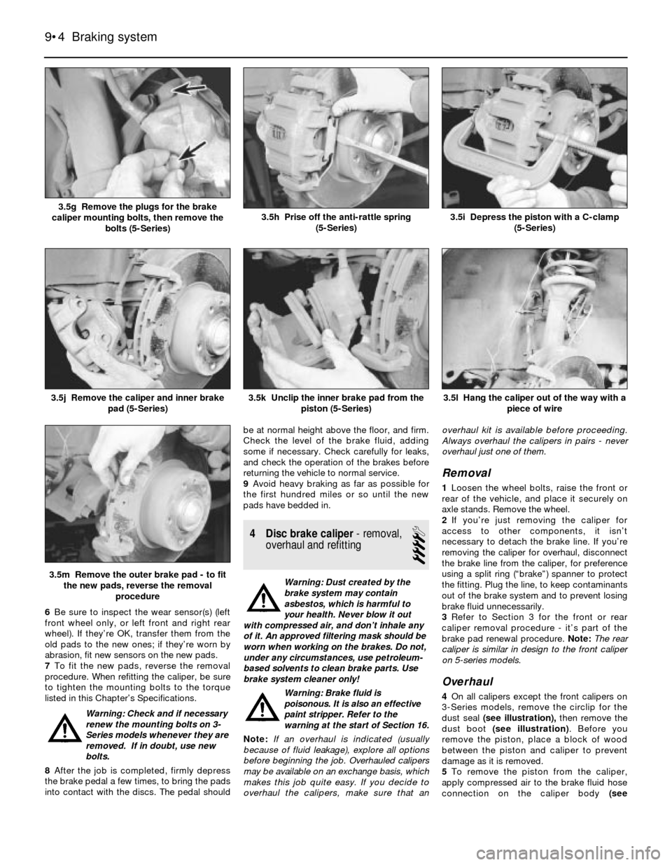
6Be sure to inspect the wear sensor(s) (left
front wheel only, or left front and right rear
wheel). If they’re OK, transfer them from the
old pads to the new ones; if they’re worn by
abrasion, fit new sensors on the new pads.
7To fit the new pads, reverse the removal
procedure. When refitting the caliper, be sure
to tighten the mounting bolts to the torque
listed in this Chapter’s Specifications.
Warning: Check and if necessary
renew the mounting bolts on 3-
Series models whenever they are
removed. If in doubt, use new
bolts.
8After the job is completed, firmly depress
the brake pedal a few times, to bring the pads
into contact with the discs. The pedal shouldbe at normal height above the floor, and firm.
Check the level of the brake fluid, adding
some if necessary. Check carefully for leaks,
and check the operation of the brakes before
returning the vehicle to normal service.
9Avoid heavy braking as far as possible for
the first hundred miles or so until the new
pads have bedded in.
4 Disc brake caliper- removal,
overhaul and refitting
4
Warning: Dust created by the
brake system may contain
asbestos, which is harmful to
your health. Never blow it out
with compressed air, and don’t inhale any
of it. An approved filtering mask should be
worn when working on the brakes. Do not,
under any circumstances, use petroleum-
based solvents to clean brake parts. Use
brake system cleaner only!
Warning: Brake fluid is
poisonous. It is also an effective
paint stripper. Refer to the
warning at the start of Section 16.
Note:If an overhaul is indicated (usually
because of fluid leakage), explore all options
before beginning the job. Overhauled calipers
may be available on an exchange basis, which
makes this job quite easy. If you decide to
overhaul the calipers, make sure that anoverhaul kit is available before proceeding.
Always overhaul the calipers in pairs - never
overhaul just one of them.
Removal
1Loosen the wheel bolts, raise the front or
rear of the vehicle, and place it securely on
axle stands. Remove the wheel.
2If you’re just removing the caliper for
access to other components, it isn’t
necessary to detach the brake line. If you’re
removing the caliper for overhaul, disconnect
the brake line from the caliper, for preference
using a split ring (“brake”) spanner to protect
the fitting. Plug the line, to keep contaminants
out of the brake system and to prevent losing
brake fluid unnecessarily.
3Refer to Section 3 for the front or rear
caliper removal procedure - it’s part of the
brake pad renewal procedure. Note:The rear
caliper is similar in design to the front caliper
on 5-series models.
Overhaul
4On all calipers except the front calipers on
3-Series models, remove the circlip for the
dust seal (see illustration),then remove the
dust boot (see illustration). Before you
remove the piston, place a block of wood
between the piston and caliper to prevent
damage as it is removed.
5To remove the piston from the caliper,
apply compressed air to the brake fluid hose
connection on the caliper body (see
9•4 Braking system
3.5l Hang the caliper out of the way with a
piece of wire
3.5m Remove the outer brake pad - to fit
the new pads, reverse the removal
procedure
3.5k Unclip the inner brake pad from the
piston (5-Series)3.5j Remove the caliper and inner brake
pad (5-Series)
3.5i Depress the piston with a C-clamp
(5-Series)3.5h Prise off the anti-rattle spring
(5-Series)3.5g Remove the plugs for the brake
caliper mounting bolts, then remove the
bolts (5-Series)
Page 138 of 228
expel the air from the master cylinder. A large
Phillips screwdriver can be used to push on
the piston assembly.
11To prevent air from being drawn back into
the master cylinder, the plug must be refitted
and tightened down before releasing the
pressure on the piston assembly.
12Repeat the procedure until brake fluid free
of air bubbles is expelled from the brake line
outlet hole. Repeat the procedure with the
other outlet hole and plug. Be sure to keep the
master cylinder reservoir filled with brake
fluid, to prevent the introduction of air into the
system.
13High pressure is not involved in the bench
bleeding procedure, so the plugs described
above need not be refitted each time the
piston is released, if wished. Instead, before
releasing the piston, simply put your finger
tightly over the hole to keep air from being
drawn back into the master cylinder. Wait
several seconds for brake fluid to be drawn
from the reservoir into the piston bore, then
depress the piston again, removing your
finger as brake fluid is expelled. Be sure to put
your finger back over the hole each time
before releasing the piston, and when the
bleeding procedure is complete for that outlet,
refit the plug and tighten it up before going on
to the other port.
Refitting
14Refit the master cylinder (together with a
new O-ring) over the studs on the brake servo,
and tighten the mounting nuts only finger-tight
at this time.
15Thread the brake line fittings into the
master cylinder. Since the master cylinder is
still a bit loose, it can be moved slightly in
order for the fittings to thread in easily. Do not
strip the threads as the fittings are tightened.
16Tighten the brake fittings securely, and
the mounting nuts to the torque listed in this
Chapter’s Specifications.
17Fill the master cylinder reservoir with fluid,
then bleed the master cylinder (only if the
cylinder has not already been bled) and the
brake system as described in Section 16.
18To bleed the cylinder on the vehicle, have
an assistant pump the brake pedal severaltimes and then hold the pedal to the floor.
Loosen the fitting nut to allow air and fluid to
escape, then tighten the nut. Repeat this
procedure on both fittings until the fluid is
clear of air bubbles. Test the operation of the
brake system carefully before returning the
vehicle to normal service.
8 Brake vacuum servo-
check, removal and refitting
3
Operating check
1Depress the brake pedal several times with
the engine off, until there is no change in the
pedal travel.
2Depress and hold the pedal, then start the
engine. If the pedal goes down slightly,
operation is normal.
Airtightness check
3Start the engine, and turn it off after one or
two minutes. Depress the brake pedal several
times slowly. If the pedal goes down further
the first time but gradually rises after the
second or third depression, the servo is
airtight.
4Depress the brake pedal while the engine is
running, then stop the engine with the pedal
depressed. If there is no change in the pedal
travel after holding the pedal for 30 seconds,
the servo is airtight.
Removal and refitting
5Dismantling the vacuum servo requires
special tools, and cannot be performed by the
home mechanic. If a problem develops, it is
recommended that a new unit be fitted.
6Remove the master cylinder as described in
Section 7.
7Disconnect the vacuum hose from the
brake servo.
8Working in the passenger compartment,
remove the glovebox and lower left-hand trim
panels.
9Remove the clip and clevis pin to
disconnect the pushrod from the cross-shaft
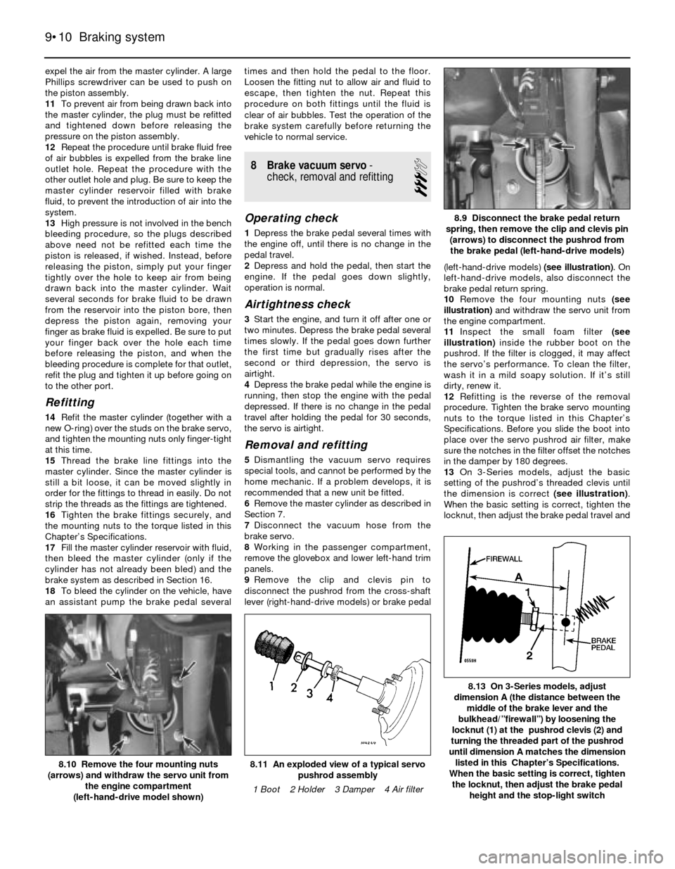
lever (right-hand-drive models) or brake pedal(left-hand-drive models) (see illustration). On
left-hand-drive models, also disconnect the
brake pedal return spring.
10Remove the four mounting nuts (see
illustration)and withdraw the servo unit from
the engine compartment.
11Inspect the small foam filter (see
illustration)inside the rubber boot on the
pushrod. If the filter is clogged, it may affect
the servo’s performance. To clean the filter,
wash it in a mild soapy solution. If it’s still
dirty, renew it.
12Refitting is the reverse of the removal
procedure. Tighten the brake servo mounting
nuts to the torque listed in this Chapter’s
Specifications. Before you slide the boot into
place over the servo pushrod air filter, make
sure the notches in the filter offset the notches
in the damper by 180 degrees.
13On 3-Series models, adjust the basic
setting of the pushrod’s threaded clevis until
the dimension is correct (see illustration).
When the basic setting is correct, tighten the
locknut, then adjust the brake pedal travel and
9•10 Braking system
8.13 On 3-Series models, adjust
dimension A (the distance between the
middle of the brake lever and the
bulkhead/”firewall”) by loosening the
locknut (1) at the pushrod clevis (2) and
turning the threaded part of the pushrod
until dimension A matches the dimension
listed in this Chapter’s Specifications.
When the basic setting is correct, tighten
the locknut, then adjust the brake pedal
height and the stop-light switch
8.11 An exploded view of a typical servo
pushrod assembly
1 Boot 2 Holder 3 Damper 4 Air filter8.10 Remove the four mounting nuts
(arrows) and withdraw the servo unit from
the engine compartment
(left-hand-drive model shown)
8.9 Disconnect the brake pedal return
spring, then remove the clip and clevis pin
(arrows) to disconnect the pushrod from
the brake pedal (left-hand-drive models)
Page 149 of 228
6 Strut or shock absorber/coil
spring- renewal
4
Note:This section applies to all front strut
assemblies and, on 5-Series models, the rear
coil-over shock absorber assemblies.
1If the struts, shock absorbers or coil springs
exhibit the telltale signs of wear (leaking fluid,
loss of damping capability, chipped, sagging
or cracked coil springs) explore all options
before beginning any work. Strut or shock
absorber assemblies complete with springs
may be available on an exchange basis, which
eliminates much time and work. Whichever
route you choose to take, check on the cost
and availability of parts before dismantling the
vehicle.
Warning: Dismantling a strut or
coil-over shock absorber
assembly is a potentially
dangerous undertaking, and
utmost attention must be directed to the
job, or serious injury may result. Use only a
high-quality spring compressor, and
carefully follow the manufacturer’s
instructions supplied with the tool. After
removing the coil spring from the strut
assembly, set it aside in a safe, isolated
area.
2Remove the strut or shock absorber
assembly (see Section 5 or 11). Mount the
assembly in a vice. Line the vice jaws with
wood or rags to prevent damage to the unit,
and don’t tighten the vice excessively.
3Following the tool manufacturer’s
instructions, fit the spring compressor (these
can be obtained at most car accessory shops,
or it may be possible to hire one) on the
spring, and compress it sufficiently to relieve
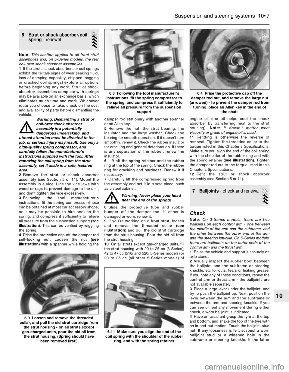
all pressure from the suspension support (see
illustration). This can be verified by wiggling
the spring.
4Prise the protective cap off the damper rod
self-locking nut. Loosen the nut (see
illustration)with a spanner while holding thedamper rod stationary with another spanner
or an Allen key.
5Remove the nut, the strut bearing, the
insulator and the large washer. Check the
bearing for smooth operation. If it doesn’t turn
smoothly, renew it. Check the rubber insulator
for cracking and general deterioration. If there
is any separation of the rubber, renew the
insulator.
6Lift off the spring retainer and the rubber
ring at the top of the spring. Check the rubber
ring for cracking and hardness. Renew it if
necessary.
7Carefully lift the compressed spring from
the assembly and set it in a safe place, such
as a steel cabinet.
Warning: Never place your head
near the end of the spring!
8Slide the protective tube and rubber
bumper off the damper rod. If either is
damaged or worn, renew it.
9If you’re working on a front strut, loosen
and remove the threaded collar (see
illustration)and pull the old strut cartridge
from the strut housing. Pour the old oil from
the strut housing.
10On all struts except gas-charged units, fill
the strut housing with 20 to 25 cc (3-Series),
42 to 47 cc (518i and 520i 5-Series models) or
20 to 25 cc (all other 5-Series models) ofengine oil (the oil helps cool the shock
absorber by transferring heat to the strut
housing). Note:It doesn’t matter what
viscosity or grade of engine oil is used.
11Refitting is otherwise the reverse of
removal. Tighten the threaded collar to the
torque listed in this Chapter’s Specifications.
Make sure you align the end of the coil spring
with the shoulder of the rubber ring and with
the spring retainer (see illustration). Tighten
the damper rod nut to the torque listed in this
Chapter’s Specifications.
12Refit the strut or shock absorber
assembly (see Section 5 or 11).
7 Balljoints- check and renewal
3
Check
Note:On 3-Series models, there are two
balljoints on each control arm - one between
the middle of the arm and the subframe, and
the other between the outer end of the arm
and the steering knuckle. On 5-Series models,
there are balljoints on the outer ends of the
control arm and the thrust arm.
1Raise the vehicle and support it securely on
axle stands.
2Visually inspect the rubber boot between
the balljoint and the subframe or steering
knuckle, etc for cuts, tears or leaking grease.
If you note any of these conditions, renew the
control arm or thrust arm - the balljoints are
not available separately.
3Place a large lever under the balljoint, and
try to push the balljoint up. Next, position the
lever between the arm and the subframe or
between the arm and steering knuckle. If you
can see or feel any movement during either
check, a worn balljoint is indicated.
4Have an assistant grasp the tyre at the top
and bottom, and shake the top of the tyre with
an in-and-out motion. Touch the balljoint stud
nut. If any looseness is felt, suspect a worn
balljoint stud or a widened hole in the
subframe or steering knuckle. If the latter
Suspension and steering systems 10•7
6.4 Prise the protective cap off the
damper rod nut, and remove the large nut
(arrowed) - to prevent the damper rod from
turning, place an Allen key in the end of
the shaft6.3 Following the tool manufacturer’s
instructions, fit the spring compressor to
the spring, and compress it sufficiently to
relieve all pressure from the suspension
support
6.11 Make sure you align the end of the
coil spring with the shoulder of the rubber
ring, and with the spring retainer
6.9 Loosen and remove the threaded
collar, and pull the old strut cartridge from
the strut housing - on all struts except
gas-charged units, pour the old oil from
the strut housing. (Spring should have
been removed first!)
10