ECO mode BMW 3 SERIES 1983 E30 Service Manual
[x] Cancel search | Manufacturer: BMW, Model Year: 1983, Model line: 3 SERIES, Model: BMW 3 SERIES 1983 E30Pages: 228, PDF Size: 7.04 MB
Page 125 of 228
Check
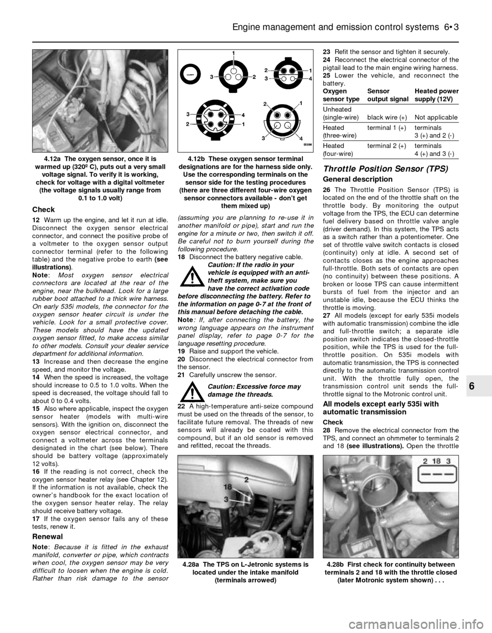
12Warm up the engine, and let it run at idle.
Disconnect the oxygen sensor electrical
connector, and connect the positive probe of
a voltmeter to the oxygen sensor output
connector terminal (refer to the following
table) and the negative probe to earth (see
illustrations).
Note:Most oxygen sensor electrical
connectors are located at the rear of the
engine, near the bulkhead. Look for a large
rubber boot attached to a thick wire harness.
On early 535i models, the connector for the
oxygen sensor heater circuit is under the
vehicle. Look for a small protective cover.
These models should have the updated
oxygen sensor fitted, to make access similar
to other models. Consult your dealer service
department for additional information.
13Increase and then decrease the engine
speed, and monitor the voltage.
14When the speed is increased, the voltage
should increase to 0.5 to 1.0 volts. When the
speed is decreased, the voltage should fall to
about 0 to 0.4 volts.
15Also where applicable, inspect the oxygen
sensor heater (models with multi-wire
sensors). With the ignition on, disconnect the
oxygen sensor electrical connector, and
connect a voltmeter across the terminals
designated in the chart (see below). There
should be battery voltage (approximately
12 volts).
16If the reading is not correct, check the
oxygen sensor heater relay (see Chapter 12).
If the information is not available, check the
owner’s handbook for the exact location of
the oxygen sensor heater relay. The relay
should receive battery voltage.
17If the oxygen sensor fails any of these
tests, renew it.
Renewal
Note: Because it is fitted in the exhaust
manifold, converter or pipe, which contracts
when cool, the oxygen sensor may be very
difficult to loosen when the engine is cold.
Rather than risk damage to the sensor(assuming you are planning to re-use it in
another manifold or pipe), start and run the
engine for a minute or two, then switch it off.
Be careful not to burn yourself during the
following procedure.
18Disconnect the battery negative cable.
Caution: If the radio in your
vehicle is equipped with an anti-
theft system, make sure you
have the correct activation code
before disconnecting the battery. Refer to
the information on page 0-7 at the front of
this manual before detaching the cable.
Note: If, after connecting the battery, the
wrong language appears on the instrument
panel display, refer to page 0-7 for the
language resetting procedure.
19Raise and support the vehicle.
20Disconnect the electrical connector from
the sensor.
21Carefully unscrew the sensor.
Caution: Excessive force may
damage the threads.
22A high-temperature anti-seize compound
must be used on the threads of the sensor, to
facilitate future removal. The threads of new
sensors will already be coated with this
compound, but if an old sensor is removed
and refitted, recoat the threads.23Refit the sensor and tighten it securely.
24Reconnect the electrical connector of the
pigtail lead to the main engine wiring harness.
25Lower the vehicle, and reconnect the
battery.
Oxygen Sensor Heated power
sensor type output signal supply (12V)
Unheated
(single-wire) black wire (+) Not applicable
Heated terminal 1 (+) terminals
(three-wire) 3 (+) and 2 (-)
Heated terminal 2 (+) terminals
(four-wire) 4 (+) and 3 (-)
Throttle Position Sensor (TPS)
General description
26The Throttle Position Sensor (TPS) is
located on the end of the throttle shaft on the
throttle body. By monitoring the output
voltage from the TPS, the ECU can determine
fuel delivery based on throttle valve angle
(driver demand). In this system, the TPS acts
as a switch rather than a potentiometer. One
set of throttle valve switch contacts is closed
(continuity) only at idle. A second set of
contacts closes as the engine approaches
full-throttle. Both sets of contacts are open
(no continuity) between these positions. A
broken or loose TPS can cause intermittent
bursts of fuel from the injector and an
unstable idle, because the ECU thinks the
throttle is moving.
27All models (except for early 535i models
with automatic transmission) combine the idle
and full-throttle switch; a separate idle
position switch indicates the closed-throttle
position, while the TPS is used for the full-
throttle position. On 535i models with
automatic transmission, the TPS is connected
directly to the automatic transmission control
unit. With the throttle fully open, the
transmission control unit sends the full-
throttle signal to the Motronic control unit.
All models except early 535i with
automatic transmission
Check
28Remove the electrical connector from the
TPS, and connect an ohmmeter to terminals 2
and 18 (see illustrations). Open the throttle
Engine management and emission control systems 6•3
4.12b These oxygen sensor terminal
designations are for the harness side only.
Use the corresponding terminals on the
sensor side for the testing procedures
(there are three different four-wire oxygen
sensor connectors available - don’t get
them mixed up)4.12a The oxygen sensor, once it is
warmed up (320º C), puts out a very small
voltage signal. To verify it is working,
check for voltage with a digital voltmeter
(the voltage signals usually range from
0.1 to 1.0 volt)
4.28b First check for continuity between
terminals 2 and 18 with the throttle closed
(later Motronic system shown) . . .4.28a The TPS on L-Jetronic systems is
located under the intake manifold
(terminals arrowed)
6
Page 126 of 228
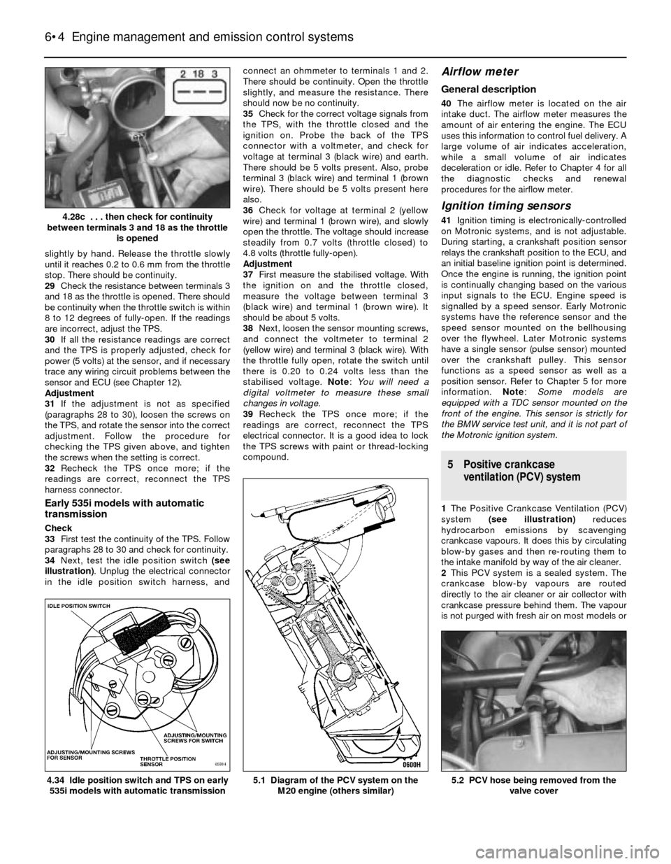
slightly by hand. Release the throttle slowly
until it reaches 0.2 to 0.6 mm from the throttle
stop. There should be continuity.
29Check the resistance between terminals 3
and 18 as the throttle is opened. There should
be continuity when the throttle switch is within
8 to 12 degrees of fully-open. If the readings
are incorrect, adjust the TPS.
30If all the resistance readings are correct
and the TPS is properly adjusted, check for
power (5 volts) at the sensor, and if necessary
trace any wiring circuit problems between the
sensor and ECU (see Chapter 12).
Adjustment
31If the adjustment is not as specified
(paragraphs 28 to 30), loosen the screws on
the TPS, and rotate the sensor into the correct
adjustment. Follow the procedure for
checking the TPS given above, and tighten
the screws when the setting is correct.
32Recheck the TPS once more; if the
readings are correct, reconnect the TPS
harness connector.
Early 535i models with automatic
transmission
Check
33First test the continuity of the TPS. Follow
paragraphs 28 to 30 and check for continuity.
34Next, test the idle position switch (see
illustration). Unplug the electrical connector
in the idle position switch harness, andconnect an ohmmeter to terminals 1 and 2.
There should be continuity. Open the throttle
slightly, and measure the resistance. There
should now be no continuity.
35Check for the correct voltage signals from
the TPS, with the throttle closed and the
ignition on. Probe the back of the TPS
connector with a voltmeter, and check for
voltage at terminal 3 (black wire) and earth.
There should be 5 volts present. Also, probe
terminal 3 (black wire) and terminal 1 (brown
wire). There should be 5 volts present here
also.
36Check for voltage at terminal 2 (yellow
wire) and terminal 1 (brown wire), and slowly
open the throttle. The voltage should increase
steadily from 0.7 volts (throttle closed) to
4.8 volts (throttle fully-open).
Adjustment
37First measure the stabilised voltage. With
the ignition on and the throttle closed,
measure the voltage between terminal 3
(black wire) and terminal 1 (brown wire). It
should be about 5 volts.
38Next, loosen the sensor mounting screws,
and connect the voltmeter to terminal 2
(yellow wire) and terminal 3 (black wire). With
the throttle fully open, rotate the switch until
there is 0.20 to 0.24 volts less than the
stabilised voltage. Note: You will need a
digital voltmeter to measure these small
changes in voltage.
39Recheck the TPS once more; if the
readings are correct, reconnect the TPS
electrical connector. It is a good idea to lock
the TPS screws with paint or thread-locking
compound.
Airflow meter
General description
40The airflow meter is located on the air
intake duct. The airflow meter measures the
amount of air entering the engine. The ECU
uses this information to control fuel delivery. A
large volume of air indicates acceleration,
while a small volume of air indicates
deceleration or idle. Refer to Chapter 4 for all
the diagnostic checks and renewal
procedures for the airflow meter.
Ignition timing sensors
41Ignition timing is electronically-controlled
on Motronic systems, and is not adjustable.
During starting, a crankshaft position sensor
relays the crankshaft position to the ECU, and
an initial baseline ignition point is determined.
Once the engine is running, the ignition point
is continually changing based on the various
input signals to the ECU. Engine speed is
signalled by a speed sensor. Early Motronic
systems have the reference sensor and the
speed sensor mounted on the bellhousing
over the flywheel. Later Motronic systems
have a single sensor (pulse sensor) mounted
over the crankshaft pulley. This sensor
functions as a speed sensor as well as a
position sensor. Refer to Chapter 5 for more
information. Note: Some models are
equipped with a TDC sensor mounted on the
front of the engine. This sensor is strictly for
the BMW service test unit, and it is not part of
the Motronic ignition system.
5 Positive crankcase
ventilation (PCV) system
1The Positive Crankcase Ventilation (PCV)
system (see illustration)reduces
hydrocarbon emissions by scavenging
crankcase vapours. It does this by circulating
blow-by gases and then re-routing them to
the intake manifold by way of the air cleaner.
2This PCV system is a sealed system. The
crankcase blow-by vapours are routed
directly to the air cleaner or air collector with
crankcase pressure behind them. The vapour
is not purged with fresh air on most models or
6•4 Engine management and emission control systems
5.2 PCV hose being removed from the
valve cover5.1 Diagram of the PCV system on the
M20 engine (others similar)4.34 Idle position switch and TPS on early
535i models with automatic transmission
4.28c . . . then check for continuity
between terminals 3 and 18 as the throttle
is opened
Page 128 of 228
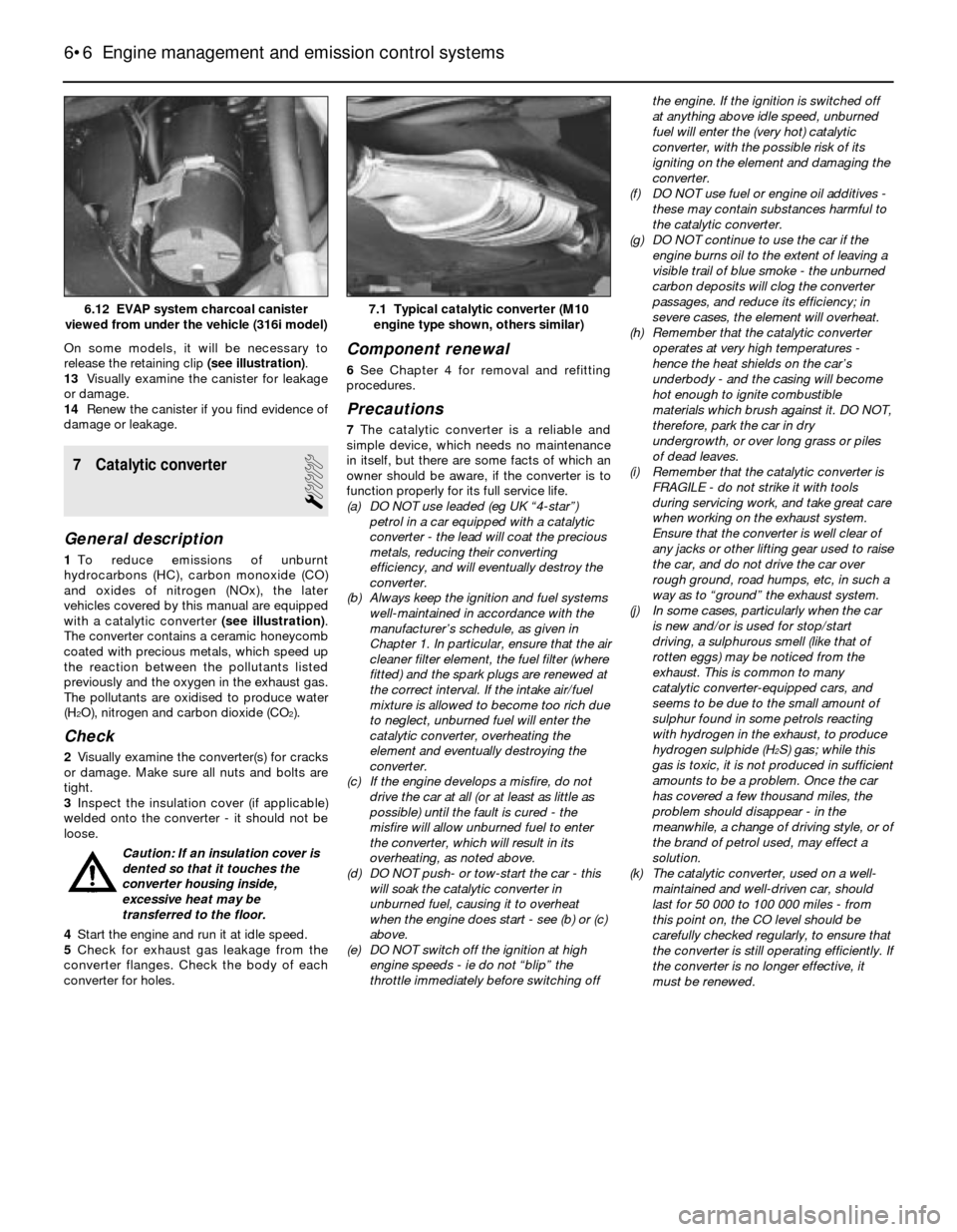
On some models, it will be necessary to
release the retaining clip (see illustration).
13Visually examine the canister for leakage
or damage.
14Renew the canister if you find evidence of
damage or leakage.
7 Catalytic converter
1
General description
1To reduce emissions of unburnt
hydrocarbons (HC), carbon monoxide (CO)
and oxides of nitrogen (NOx), the later
vehicles covered by this manual are equipped
with a catalytic converter (see illustration).
The converter contains a ceramic honeycomb
coated with precious metals, which speed up
the reaction between the pollutants listed
previously and the oxygen in the exhaust gas.
The pollutants are oxidised to produce water
(H
2O), nitrogen and carbon dioxide (CO2).
Check
2Visually examine the converter(s) for cracks
or damage. Make sure all nuts and bolts are
tight.
3Inspect the insulation cover (if applicable)
welded onto the converter - it should not be
loose.
Caution: If an insulation cover is
dented so that it touches the
converter housing inside,
excessive heat may be
transferred to the floor.
4Start the engine and run it at idle speed.
5Check for exhaust gas leakage from the
converter flanges. Check the body of each
converter for holes.
Component renewal
6See Chapter 4 for removal and refitting
procedures.
Precautions
7The catalytic converter is a reliable and
simple device, which needs no maintenance
in itself, but there are some facts of which an
owner should be aware, if the converter is to
function properly for its full service life.
(a) DO NOT use leaded (eg UK “4-star”)
petrol in a car equipped with a catalytic
converter - the lead will coat the precious
metals, reducing their converting
efficiency, and will eventually destroy the
converter.
(b) Always keep the ignition and fuel systems
well-maintained in accordance with the
manufacturer’s schedule, as given in
Chapter 1. In particular, ensure that the air
cleaner filter element, the fuel filter (where
fitted) and the spark plugs are renewed at
the correct interval. If the intake air/fuel
mixture is allowed to become too rich due
to neglect, unburned fuel will enter the
catalytic converter, overheating the
element and eventually destroying the
converter.
(c) If the engine develops a misfire, do not
drive the car at all (or at least as little as
possible) until the fault is cured - the
misfire will allow unburned fuel to enter
the converter, which will result in its
overheating, as noted above.
(d) DO NOT push- or tow-start the car - this
will soak the catalytic converter in
unburned fuel, causing it to overheat
when the engine does start - see (b) or (c)
above.
(e) DO NOT switch off the ignition at high
engine speeds - ie do not “blip” the
throttle immediately before switching offthe engine. If the ignition is switched off
at anything above idle speed, unburned
fuel will enter the (very hot) catalytic
converter, with the possible risk of its
igniting on the element and damaging the
converter.
(f) DO NOT use fuel or engine oil additives -
these may contain substances harmful to
the catalytic converter.
(g) DO NOT continue to use the car if the
engine burns oil to the extent of leaving a
visible trail of blue smoke - the unburned
carbon deposits will clog the converter
passages, and reduce its efficiency; in
severe cases, the element will overheat.
(h) Remember that the catalytic converter
operates at very high temperatures -
hence the heat shields on the car’s
underbody - and the casing will become
hot enough to ignite combustible
materials which brush against it. DO NOT,
therefore, park the car in dry
undergrowth, or over long grass or piles
of dead leaves.
(i) Remember that the catalytic converter is
FRAGILE - do not strike it with tools
during servicing work, and take great care
when working on the exhaust system.
Ensure that the converter is well clear of
any jacks or other lifting gear used to raise
the car, and do not drive the car over
rough ground, road humps, etc, in such a
way as to “ground” the exhaust system.
(j) In some cases, particularly when the car
is new and/or is used for stop/start
driving, a sulphurous smell (like that of
rotten eggs) may be noticed from the
exhaust. This is common to many
catalytic converter-equipped cars, and
seems to be due to the small amount of
sulphur found in some petrols reacting
with hydrogen in the exhaust, to produce
hydrogen sulphide (H
2S) gas; while this
gas is toxic, it is not produced in sufficient
amounts to be a problem. Once the car
has covered a few thousand miles, the
problem should disappear - in the
meanwhile, a change of driving style, or of
the brand of petrol used, may effect a
solution.
(k) The catalytic converter, used on a well-
maintained and well-driven car, should
last for 50 000 to 100 000 miles - from
this point on, the CO level should be
carefully checked regularly, to ensure that
the converter is still operating efficiently. If
the converter is no longer effective, it
must be renewed.
6•6 Engine management and emission control systems
7.1 Typical catalytic converter (M10
engine type shown, others similar)6.12 EVAP system charcoal canister
viewed from under the vehicle (316i model)
Page 137 of 228
friction surfaces of the brake shoes or
drums.
12Make sure the adjuster assembly is
properly engaged with its respective notch in
the handbrake lever.
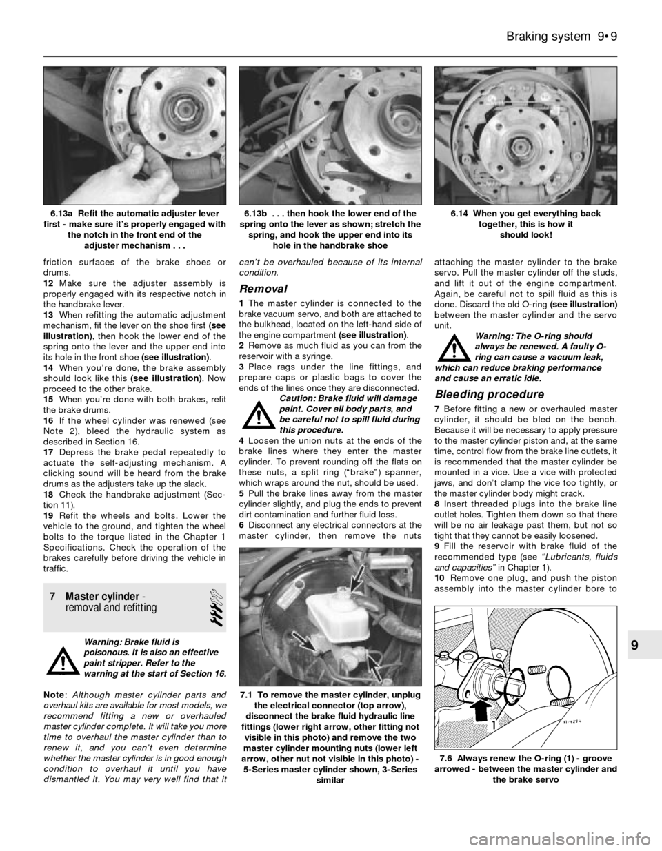
13When refitting the automatic adjustment
mechanism, fit the lever on the shoe first (see
illustration), then hook the lower end of the
spring onto the lever and the upper end into
its hole in the front shoe (see illustration).
14When you’re done, the brake assembly
should look like this (see illustration). Now
proceed to the other brake.
15When you’re done with both brakes, refit
the brake drums.
16If the wheel cylinder was renewed (see
Note 2), bleed the hydraulic system as
described in Section 16.
17Depress the brake pedal repeatedly to
actuate the self-adjusting mechanism. A
clicking sound will be heard from the brake
drums as the adjusters take up the slack.
18Check the handbrake adjustment (Sec-
tion 11).
19Refit the wheels and bolts. Lower the
vehicle to the ground, and tighten the wheel
bolts to the torque listed in the Chapter 1
Specifications. Check the operation of the
brakes carefully before driving the vehicle in
traffic.
7 Master cylinder-
removal and refitting
3
Warning: Brake fluid is
poisonous. It is also an effective
paint stripper. Refer to the
warning at the start of Section 16.
Note: Although master cylinder parts and
overhaul kits are available for most models, we
recommend fitting a new or overhauled
master cylinder complete. It will take you more
time to overhaul the master cylinder than to
renew it, and you can’t even determine
whether the master cylinder is in good enough
condition to overhaul it until you have
dismantled it. You may very well find that itcan’t be overhauled because of its internal
condition.
Removal
1The master cylinder is connected to the
brake vacuum servo, and both are attached to
the bulkhead, located on the left-hand side of
the engine compartment (see illustration).
2Remove as much fluid as you can from the
reservoir with a syringe.
3Place rags under the line fittings, and
prepare caps or plastic bags to cover the
ends of the lines once they are disconnected.
Caution: Brake fluid will damage
paint. Cover all body parts, and
be careful not to spill fluid during
this procedure.
4Loosen the union nuts at the ends of the
brake lines where they enter the master
cylinder. To prevent rounding off the flats on
these nuts, a split ring (“brake”) spanner,
which wraps around the nut, should be used.
5Pull the brake lines away from the master
cylinder slightly, and plug the ends to prevent
dirt contamination and further fluid loss.
6Disconnect any electrical connectors at the
master cylinder, then remove the nutsattaching the master cylinder to the brake
servo. Pull the master cylinder off the studs,
and lift it out of the engine compartment.
Again, be careful not to spill fluid as this is
done. Discard the old O-ring (see illustration)
between the master cylinder and the servo
unit.
Warning: The O-ring should
always be renewed. A faulty O-
ring can cause a vacuum leak,
which can reduce braking performance
and cause an erratic idle.
Bleeding procedure
7Before fitting a new or overhauled master
cylinder, it should be bled on the bench.
Because it will be necessary to apply pressure
to the master cylinder piston and, at the same
time, control flow from the brake line outlets, it
is recommended that the master cylinder be
mounted in a vice. Use a vice with protected
jaws, and don’t clamp the vice too tightly, or
the master cylinder body might crack.
8Insert threaded plugs into the brake line
outlet holes. Tighten them down so that there
will be no air leakage past them, but not so
tight that they cannot be easily loosened.
9Fill the reservoir with brake fluid of the
recommended type (see “Lubricants, fluids
and capacities” in Chapter 1).
10Remove one plug, and push the piston
assembly into the master cylinder bore to
Braking system 9•9
6.14 When you get everything back
together, this is how it
should look! 6.13b . . . then hook the lower end of the
spring onto the lever as shown; stretch the
spring, and hook the upper end into its
hole in the handbrake shoe6.13a Refit the automatic adjuster lever
first - make sure it’s properly engaged with
the notch in the front end of the
adjuster mechanism . . .
7.6 Always renew the O-ring (1) - groove
arrowed - between the master cylinder and
the brake servo
7.1 To remove the master cylinder, unplug
the electrical connector (top arrow),
disconnect the brake fluid hydraulic line
fittings (lower right arrow, other fitting not
visible in this photo) and remove the two
master cylinder mounting nuts (lower left
arrow, other nut not visible in this photo) -
5-Series master cylinder shown, 3-Series
similar
9
Page 138 of 228
expel the air from the master cylinder. A large
Phillips screwdriver can be used to push on
the piston assembly.
11To prevent air from being drawn back into
the master cylinder, the plug must be refitted
and tightened down before releasing the
pressure on the piston assembly.
12Repeat the procedure until brake fluid free
of air bubbles is expelled from the brake line
outlet hole. Repeat the procedure with the
other outlet hole and plug. Be sure to keep the
master cylinder reservoir filled with brake
fluid, to prevent the introduction of air into the
system.
13High pressure is not involved in the bench
bleeding procedure, so the plugs described
above need not be refitted each time the
piston is released, if wished. Instead, before
releasing the piston, simply put your finger
tightly over the hole to keep air from being
drawn back into the master cylinder. Wait
several seconds for brake fluid to be drawn
from the reservoir into the piston bore, then
depress the piston again, removing your
finger as brake fluid is expelled. Be sure to put
your finger back over the hole each time
before releasing the piston, and when the
bleeding procedure is complete for that outlet,
refit the plug and tighten it up before going on
to the other port.
Refitting
14Refit the master cylinder (together with a
new O-ring) over the studs on the brake servo,
and tighten the mounting nuts only finger-tight
at this time.
15Thread the brake line fittings into the
master cylinder. Since the master cylinder is
still a bit loose, it can be moved slightly in
order for the fittings to thread in easily. Do not
strip the threads as the fittings are tightened.
16Tighten the brake fittings securely, and
the mounting nuts to the torque listed in this
Chapter’s Specifications.
17Fill the master cylinder reservoir with fluid,
then bleed the master cylinder (only if the
cylinder has not already been bled) and the
brake system as described in Section 16.
18To bleed the cylinder on the vehicle, have
an assistant pump the brake pedal severaltimes and then hold the pedal to the floor.
Loosen the fitting nut to allow air and fluid to
escape, then tighten the nut. Repeat this
procedure on both fittings until the fluid is
clear of air bubbles. Test the operation of the
brake system carefully before returning the
vehicle to normal service.
8 Brake vacuum servo-
check, removal and refitting
3
Operating check
1Depress the brake pedal several times with
the engine off, until there is no change in the
pedal travel.
2Depress and hold the pedal, then start the
engine. If the pedal goes down slightly,
operation is normal.
Airtightness check
3Start the engine, and turn it off after one or
two minutes. Depress the brake pedal several
times slowly. If the pedal goes down further
the first time but gradually rises after the
second or third depression, the servo is
airtight.
4Depress the brake pedal while the engine is
running, then stop the engine with the pedal
depressed. If there is no change in the pedal
travel after holding the pedal for 30 seconds,
the servo is airtight.
Removal and refitting
5Dismantling the vacuum servo requires
special tools, and cannot be performed by the
home mechanic. If a problem develops, it is
recommended that a new unit be fitted.
6Remove the master cylinder as described in
Section 7.
7Disconnect the vacuum hose from the
brake servo.
8Working in the passenger compartment,
remove the glovebox and lower left-hand trim
panels.
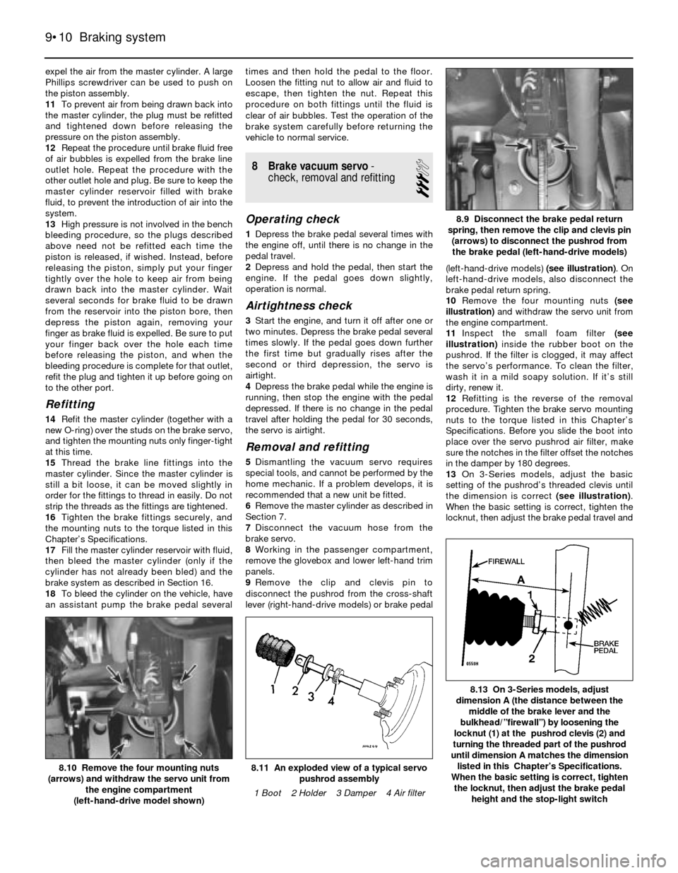
9Remove the clip and clevis pin to
disconnect the pushrod from the cross-shaft
lever (right-hand-drive models) or brake pedal(left-hand-drive models) (see illustration). On
left-hand-drive models, also disconnect the
brake pedal return spring.
10Remove the four mounting nuts (see
illustration)and withdraw the servo unit from
the engine compartment.
11Inspect the small foam filter (see
illustration)inside the rubber boot on the
pushrod. If the filter is clogged, it may affect
the servo’s performance. To clean the filter,
wash it in a mild soapy solution. If it’s still
dirty, renew it.
12Refitting is the reverse of the removal
procedure. Tighten the brake servo mounting
nuts to the torque listed in this Chapter’s
Specifications. Before you slide the boot into
place over the servo pushrod air filter, make
sure the notches in the filter offset the notches
in the damper by 180 degrees.
13On 3-Series models, adjust the basic
setting of the pushrod’s threaded clevis until
the dimension is correct (see illustration).
When the basic setting is correct, tighten the
locknut, then adjust the brake pedal travel and
9•10 Braking system
8.13 On 3-Series models, adjust
dimension A (the distance between the
middle of the brake lever and the
bulkhead/”firewall”) by loosening the
locknut (1) at the pushrod clevis (2) and
turning the threaded part of the pushrod
until dimension A matches the dimension
listed in this Chapter’s Specifications.
When the basic setting is correct, tighten
the locknut, then adjust the brake pedal
height and the stop-light switch
8.11 An exploded view of a typical servo
pushrod assembly
1 Boot 2 Holder 3 Damper 4 Air filter8.10 Remove the four mounting nuts
(arrows) and withdraw the servo unit from
the engine compartment
(left-hand-drive model shown)
8.9 Disconnect the brake pedal return
spring, then remove the clip and clevis pin
(arrows) to disconnect the pushrod from
the brake pedal (left-hand-drive models)
Page 141 of 228
then back off the adjuster until the shoes
don’t drag (see Section 11). Refit the wheel
bolts, and tighten them to the torque given in
Chapter 1 Specifications.
13 Brake pedal- adjustment
1
Note:You should always adjust brake pedal
height after the master cylinder or brake servo
has been removed or renewed. You should
also adjust the stop-light switch (see Sec-
tion 14).
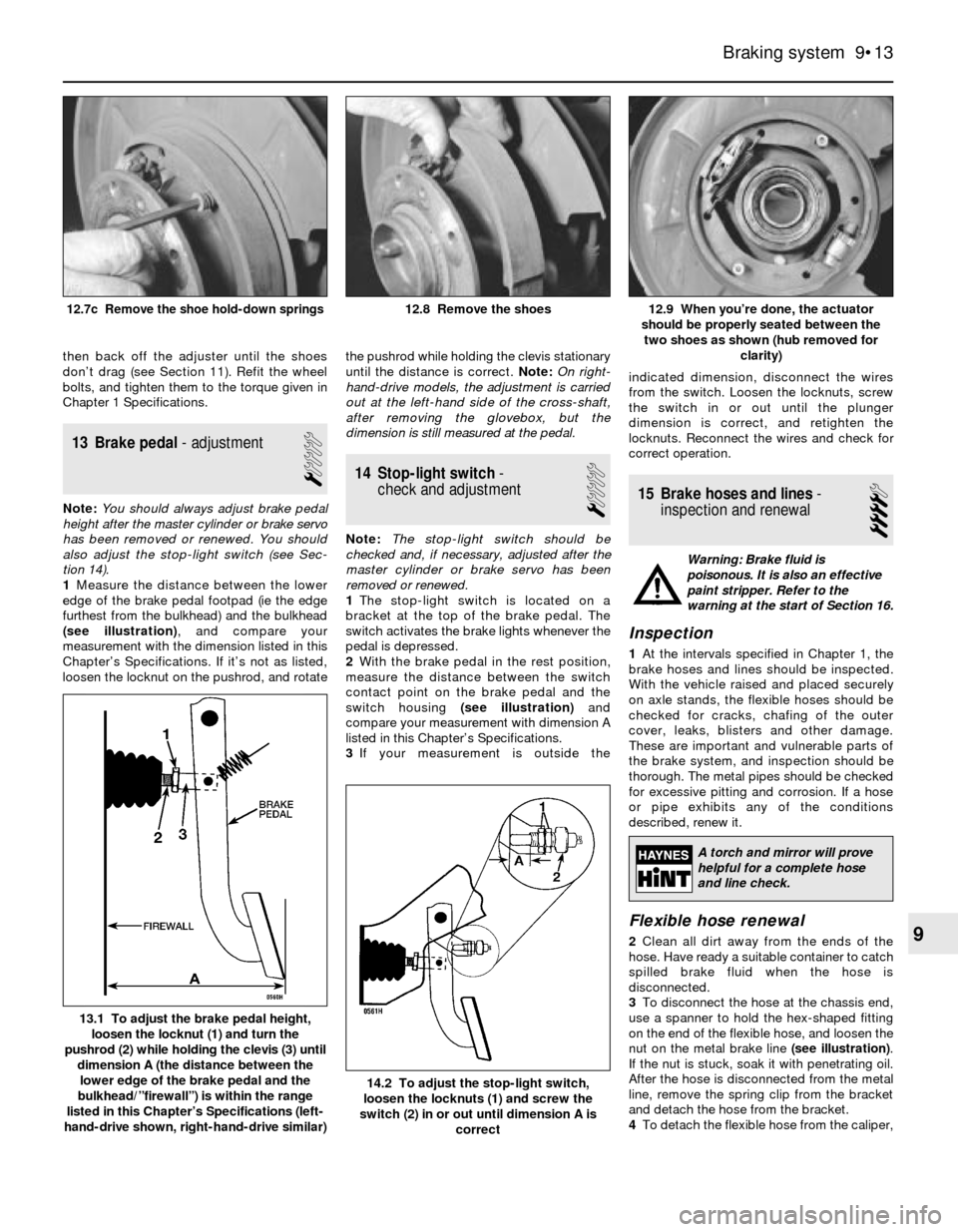
1Measure the distance between the lower
edge of the brake pedal footpad (ie the edge
furthest from the bulkhead) and the bulkhead
(see illustration), and compare your
measurement with the dimension listed in this
Chapter’s Specifications. If it’s not as listed,
loosen the locknut on the pushrod, and rotatethe pushrod while holding the clevis stationary
until the distance is correct. Note:On right-
hand-drive models, the adjustment is carried
out at the left-hand side of the cross-shaft,
after removing the glovebox, but the
dimension is still measured at the pedal.
14 Stop-light switch-
check and adjustment
1
Note:The stop-light switch should be
checked and, if necessary, adjusted after the
master cylinder or brake servo has been
removed or renewed.
1The stop-light switch is located on a
bracket at the top of the brake pedal. The
switch activates the brake lights whenever the
pedal is depressed.
2With the brake pedal in the rest position,
measure the distance between the switch
contact point on the brake pedal and the
switch housing (see illustration)and
compare your measurement with dimension A
listed in this Chapter’s Specifications.
3If your measurement is outside theindicated dimension, disconnect the wires
from the switch. Loosen the locknuts, screw
the switch in or out until the plunger
dimension is correct, and retighten the
locknuts. Reconnect the wires and check for
correct operation.
15 Brake hoses and lines-
inspection and renewal
4
Warning: Brake fluid is
poisonous. It is also an effective
paint stripper. Refer to the
warning at the start of Section 16.
Inspection
1At the intervals specified in Chapter 1, the
brake hoses and lines should be inspected.
With the vehicle raised and placed securely
on axle stands, the flexible hoses should be
checked for cracks, chafing of the outer
cover, leaks, blisters and other damage.
These are important and vulnerable parts of
the brake system, and inspection should be
thorough. The metal pipes should be checked
for excessive pitting and corrosion. If a hose
or pipe exhibits any of the conditions
described, renew it.
Flexible hose renewal
2Clean all dirt away from the ends of the
hose. Have ready a suitable container to catch
spilled brake fluid when the hose is
disconnected.
3To disconnect the hose at the chassis end,
use a spanner to hold the hex-shaped fitting
on the end of the flexible hose, and loosen the
nut on the metal brake line (see illustration).
If the nut is stuck, soak it with penetrating oil.
After the hose is disconnected from the metal
line, remove the spring clip from the bracket
and detach the hose from the bracket.
4To detach the flexible hose from the caliper,
Braking system 9•13
12.9 When you’re done, the actuator
should be properly seated between the
two shoes as shown (hub removed for
clarity)12.8 Remove the shoes12.7c Remove the shoe hold-down springs
14.2 To adjust the stop-light switch,
loosen the locknuts (1) and screw the
switch (2) in or out until dimension A is
correct
13.1 To adjust the brake pedal height,
loosen the locknut (1) and turn the
pushrod (2) while holding the clevis (3) until
dimension A (the distance between the
lower edge of the brake pedal and the
bulkhead/”firewall”) is within the range
listed in this Chapter’s Specifications (left-
hand-drive shown, right-hand-drive similar)
9
A torch and mirror will prove
helpful for a complete hose
and line check.
Page 148 of 228
Bush inspection and renewal
8If the bush is cracked, torn or otherwise
deteriorated, take the arm to a BMW dealer
service department or an engineering works,
and have it pressed out and a new bush
pressed in. Bushes should always be renewed
in pairs (a new bush should be fitted in each
arm, and both bushes should have the same
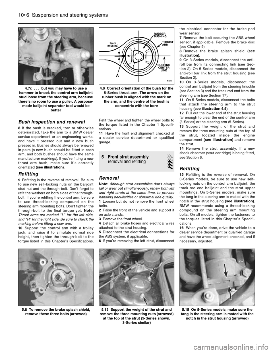
manufacturer markings). If you’re fitting a new
thrust arm bush, make sure it’s correctly
orientated (see illustration).
Refitting
9Refitting is the reverse of removal. Be sure
to use new self-locking nuts on the balljoint
stud nut and the through-bolt. Don’t forget to
refit the washers on both sides of the through-
bolt. If you’re refitting the control arm, be sure
to use thread-locking compound on the
steering arm mounting bolts. Don’t tighten the
through-bolt to the final torque yet. Note:
Thrust arms are marked “L” for the left side,
and “R” for the right side. Be sure to check the
marking before fitting a new arm.
10Support the control arm with a trolley
jack, and raise it to simulate normal ride
height, then tighten the through-bolt to the
torque listed in this Chapter’s Specifications.Refit the wheel and tighten the wheel bolts to
the torque listed in the Chapter 1 Specifi-
cations.
11Have the front end alignment checked at
a dealer service department or qualified
garage.
5 Front strut assembly-
removal and refitting
3
Removal
Note:Although strut assemblies don’t always
fail or wear out simultaneously, renew both left
and right struts at the same time, to prevent
handling peculiarities or abnormal ride quality.
1Loosen but do not remove the front wheel
bolts.
2Raise the front of the vehicle and support it
on axle stands.
3Remove the front wheel.
4Detach all brake hoses and electrical wires
attached to the strut housing.
5Disconnect the electrical connections for
the ABS system, if applicable.
6If you’re removing the left strut, disconnectthe electrical connector for the brake pad
wear sensor.
7Remove the bolt securing the ABS wheel
sensor, if applicable. Remove the brake disc
(see Chapter 9).
8Remove the brake splash shield (see
illustration).
9On 3-Series models, disconnect the anti-
roll bar from its connecting link (see Sec-
tion 2). On 5-Series models, disconnect the
anti-roll bar link from the strut housing (see
Section 2).
10On 3-Series models, disconnect the
control arm balljoint from the steering knuckle
(see Section 3) and the track rod end from the
steering arm (see Section 17).
11On 5-Series models, disconnect the bolts
that attach the steering arm to the strut
housing (see illustration 4.5).
12Pull out the lower end of the strut housing
far enough to clear the end of the control arm
(3-Series) or the steering arm (5-Series).
13Support the weight of the strut and
remove the three mounting nuts at the top of
the strut, located inside the engine
compartment (see illustration)and remove
the strut.
14Remove the strut assembly. If a new
shock absorber (strut cartridge) is being fitted,
see Section 6.
Refitting
15Refitting is the reverse of removal. On
3-Series models, be sure to use new self-
locking nuts on the control arm balljoint, the
track rod end balljoint and the strut upper
mountings. On 5-Series models, make sure
the tang in the steering arm is mated with the
notch in the strut housing (see illustration).
BMW recommends using a thread-locking
compound on the steering arm mounting
bolts. On all models, tighten the fasteners to
the torques listed in this Chapter’s Specifi-
cations.
16When you’re done, drive the vehicle to a
dealer service department or qualified garage
and have the wheel alignment checked, and if
necessary, adjusted.
10•6 Suspension and steering systems
5.15 On 5-Series models, make sure the
tang in the steering arm is mated with the
notch in the strut housing (arrowed)5.13 Support the weight of the strut and
remove the three mounting nuts (arrowed)
at the top of the strut (5-Series shown,
3-Series similar)5.8 To remove the brake splash shield,
remove these three bolts (arrowed)
4.8 Correct orientation of the bush for the
5-Series thrust arm. The arrow on the
rubber bush is aligned with the mark on
the arm, and the centre of the bush is
concentric with the bore4.7c . . . but you may have to use a
hammer to knock the control arm balljoint
stud loose from the steering arm, because
there’s no room to use a puller. A purpose-
made balljoint separator tool would be
better
Page 155 of 228
Where power-assistance is fitted, hydraulic
pressure (provided by an engine-driven pump)
delivers power steering fluid to the rack-and-
pinion steering gear or the recirculating-ball
steering box - this enhances steering
response and reduces steering effort.
Aside from maintaining the proper level of
power steering fluid in the system and
checking the tension of the drivebelt (see
Chapter 1, where applicable), the steering
system requires no maintenance. However,
on high-mileage vehicles, the track rod end
balljoints, the universal joints on either end of
the universal joint shaft, and the rubber
coupling between the steering column and the
universal joint shaft will wear, develop
excessive play, and cause the steering to feel
somewhat loose. At this point, you’ll have to
renew these items; they can’t be serviced.
Before you conclude that the steering
system needs work, however, always check
the tyres (see Section 25) and tyre pressures
(see Chapter 1). Also inspect the bearings in
the strut upper mounts (see Section 5), the
front hub bearings (see Section 8) and other
suspension parts, which may also be
contributing to an imprecise steering feel.
17 Track rod ends-
removal and refitting
4
1Loosen but do not remove the wheel bolts,
then raise the front of the vehicle and secure it
on axle stands. Remove the front wheel.
3-Series models
2Loosen the nut on the track rod balljoint
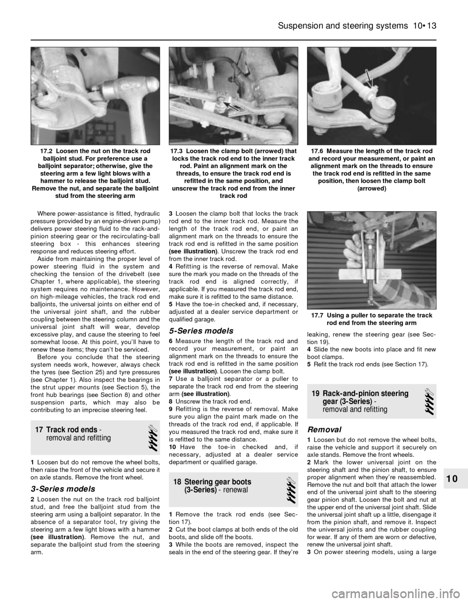
stud, and free the balljoint stud from the
steering arm using a balljoint separator. In the
absence of a separator tool, try giving the
steering arm a few light blows with a hammer
(see illustration). Remove the nut, and
separate the balljoint stud from the steering
arm.3Loosen the clamp bolt that locks the track
rod end to the inner track rod. Measure the
length of the track rod end, or paint an
alignment mark on the threads to ensure the
track rod end is refitted in the same position
(see illustration). Unscrew the track rod end
from the inner track rod.
4Refitting is the reverse of removal. Make
sure the mark you made on the threads of the
track rod end is aligned correctly, if
applicable. If you measured the track rod end,
make sure it is refitted to the same distance.
5Have the toe-in checked and, if necessary,
adjusted at a dealer service department or
qualified garage.
5-Series models
6Measure the length of the track rod and
record your measurement, or paint an
alignment mark on the threads to ensure the
track rod end is refitted in the same position
(see illustration). Loosen the clamp bolt.
7Use a balljoint separator or a puller to
separate the track rod end from the steering
arm (see illustration).
8Unscrew the track rod end.
9Refitting is the reverse of removal. Make
sure you align the paint mark made on the
threads of the track rod end, if applicable. If
you measured the track rod end, make sure it
is refitted to the same distance.
10Have the toe-in checked and, if
necessary, adjusted at a dealer service
department or qualified garage.
18 Steering gear boots
(3-Series)- renewal
4
1Remove the track rod ends (see Sec-
tion 17).
2Cut the boot clamps at both ends of the old
boots, and slide off the boots.
3While the boots are removed, inspect the
seals in the end of the steering gear. If they’releaking, renew the steering gear (see Sec-
tion 19).
4Slide the new boots into place and fit new
boot clamps.
5Refit the track rod ends (see Section 17).
19 Rack-and-pinion steering
gear (3-Series)-
removal and refitting
4
Removal
1Loosen but do not remove the wheel bolts,
raise the vehicle and support it securely on
axle stands. Remove the front wheels.
2Mark the lower universal joint on the
steering shaft and the pinion shaft, to ensure
proper alignment when they’re reassembled.
Remove the nut and bolt that attach the lower
end of the universal joint shaft to the steering
gear pinion shaft. Loosen the bolt and nut at
the upper end of the universal joint shaft. Slide
the universal joint shaft up a little, disengage it
from the pinion shaft, and remove it. Inspect
the universal joints and the rubber coupling
for wear. If any of them are worn or defective,
renew the universal joint shaft.
3On power steering models, using a large
Suspension and steering systems 10•13
17.6 Measure the length of the track rod
and record your measurement, or paint an
alignment mark on the threads to ensure
the track rod end is refitted in the same
position, then loosen the clamp bolt
(arrowed)17.3 Loosen the clamp bolt (arrowed) that
locks the track rod end to the inner track
rod. Paint an alignment mark on the
threads, to ensure the track rod end is
refitted in the same position, and
unscrew the track rod end from the inner
track rod17.2 Loosen the nut on the track rod
balljoint stud. For preference use a
balljoint separator; otherwise, give the
steering arm a few light blows with a
hammer to release the balljoint stud.
Remove the nut, and separate the balljoint
stud from the steering arm
17.7 Using a puller to separate the track
rod end from the steering arm
10
Page 156 of 228
syringe or hand pump, empty the power
steering fluid reservoir.
4On power steering models, remove the
banjo bolts and disconnect the power
steering pressure and return lines from the
steering gear. Place a container under the
lines to catch spilled fluid. Plug the lines to
prevent excessive fluid loss and
contamination. Discard the sealing washers
(new ones should be used when
reassembling).
5Disconnect the track rod ends from the
steering arms (see Section 17).
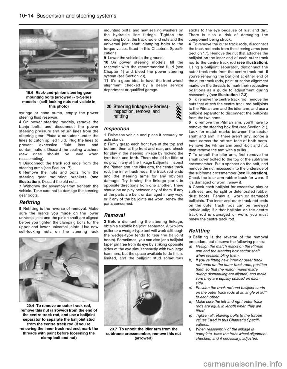
6Remove the nuts and bolts from the
steering gear mounting brackets (see
illustration). Discard the old nuts.
7Withdraw the assembly from beneath the
vehicle. Take care not to damage the steering
gear boots.
Refitting
8Refitting is the reverse of removal. Make
sure the marks you made on the lower
universal joint and the pinion shaft are aligned
before you tighten the clamping bolts for the
upper and lower universal joints. Use new
self-locking nuts on the steering rackmounting bolts, and new sealing washers on
the hydraulic line fittings. Tighten the
mounting bolts, the track rod end nuts and the
universal joint shaft clamping bolts to the
torque values listed in this Chapter’s Specifi-
cations.
9Lower the vehicle to the ground.
10On power steering models, fill the
reservoir with the recommended fluid (see
Chapter 1) and bleed the power steering
system (see Section 23).
11It’s a good idea to have the front wheel
alignment checked by a dealer service
department or qualified garage.
20 Steering linkage (5-Series)-
inspection, removal and
refitting
4
Inspection
1Raise the vehicle and place it securely on
axle stands.
2Firmly grasp each front tyre at the top and
bottom, then at the front and rear, and check
for play in the steering linkage by rocking the
tyre back and forth. There should be little or
no play in any of the linkage balljoints. Inspect
the Pitman arm, the idler arm, the centre track
rod, the inner track rods, the track rod ends
and the steering arms for any obvious
damage. Try forcing the linkage parts in
opposite directions from one another. There
should be no play between any of them. If any
of the parts are bent or damaged in any way,
or if any of the balljoints are worn, renew the
parts concerned.
Removal
3Before dismantling the steering linkage,
obtain a suitable balljoint separator. A two-jaw
puller or a wedge-type tool will work (although
the wedge-type tends to tear the balljoint
boots). Sometimes, you can also jar a balljoint
taper pin free from its eye by striking opposite
sides of the eye simultaneously with two large
hammers, but the space available to do this is
limited, and the balljoint stud sometimessticks to the eye because of rust and dirt.
There is also a risk of damaging the
component being struck.
4To remove the outer track rods, disconnect
the track rod ends from the steering arms (see
Section 17). Remove the nut that attaches the
balljoint on the inner end of each outer track
rod to the centre track rod (see illustration).
Using a balljoint separator, disconnect the
outer track rods from the centre track rod. If
you’re renewing the balljoint at either end of
the outer track rods, paint or scribe alignment
marks on the threads to mark their respective
positions as a guide to adjustment during
reassembly (see illustration 17.3).
5To remove the centre track rod, remove the
nuts that attach the centre track rod balljoints
to the Pitman arm and the idler arm, and use a
balljoint separator to disconnect the balljoints
from the two arms.
6To remove the Pitman arm, you’ll have to
remove the steering box first (see Section 21).
Look for match marks between the sector
shaft and arm. If there aren’t any, scribe a
mark across the bottom face of both parts.
Remove the Pitman arm pinch-bolt and nut,
then remove the arm with a puller.
7To unbolt the idler arm, first remove the
small cover bolted to the top of the subframe
crossmember. Put a spanner on the bolt, and
remove the nut recessed into the underside of
the subframe crossmember (see illustration).
Check the idler arm rubber bush for wear. If
it’s damaged or worn, renew it.
8Check each balljoint for excessive play or
stiffness, and for split or deteriorated rubber
dust boots. Renew all worn or damaged
balljoints. The inner and outer track rod ends
on the outer track rods can be renewed
individually; if either balljoint on the centre
track rod is damaged or worn, you must
renew the centre track rod.
Refitting
9Refitting is the reverse of the removal
procedure, but observe the following points:
a) Realign the match marks on the Pitman
arm and the steering box sector shaft
when reassembling them.
b) If you’re fitting new inner or outer track
rod ends on the outer track rods, position
them so that the match marks made
during dismantling are aligned, and make
sure they are equally spaced on each
side.
c) Position the track rod end balljoint studs
on the outer track rods at an angle of 90°
to each other.
d) Make sure the left and right outer track
rods are equal in length when they are
fitted.
e) Tighten all retaining bolts to the torque
values listed in this Chapter’s Specifi-
cations.
f) When reassembly of the linkage is
complete, have the front wheel alignment
checked, and if necessary, adjusted.
10•14 Suspension and steering systems
20.7 To unbolt the idler arm from the
subframe crossmember, remove this nut
(arrowed)
20.4 To remove an outer track rod,
remove this nut (arrowed) from the end of
the centre track rod, and use a balljoint
separator to separate the balljoint stud
from the centre track rod (if you’re
renewing the inner track rod end, mark the
threads with paint before loosening the
clamp bolt and nut)
19.6 Rack-and-pinion steering gear
mounting bolts (arrowed) - 3-Series
models - (self-locking nuts not visible in
this photo)
Page 157 of 228
21 Steering box (5-Series)-
removal and refitting
4
Removal
Note:If you find that the steering box is
defective, it is not recommended that you
overhaul it. Because of the special tools
needed to do the job, it is best to let your
dealer service department overhaul it for you
(otherwise, fit a new unit). Removal and
refitting the steering box is outlined here.
1On 5-Series E28 (“old-shape”) models,
discharge the hydraulic system by depressing
the brake pedal about 20 times.
2Using a large syringe or hand pump, empty
the power steering fluid reservoir (see Chap-
ter 1).
3Raise the front of the vehicle and support it
securely on axle stands.
4Support the front of the engine with a trolley
jack. Place a block of wood between the jack
head and the sump to protect the sump from
damage.
5Remove the pivot bolts from the inner ends
of the front control arms (see Section 4).
6Remove the nuts from the left and right
engine mountings (see Chapter 2).
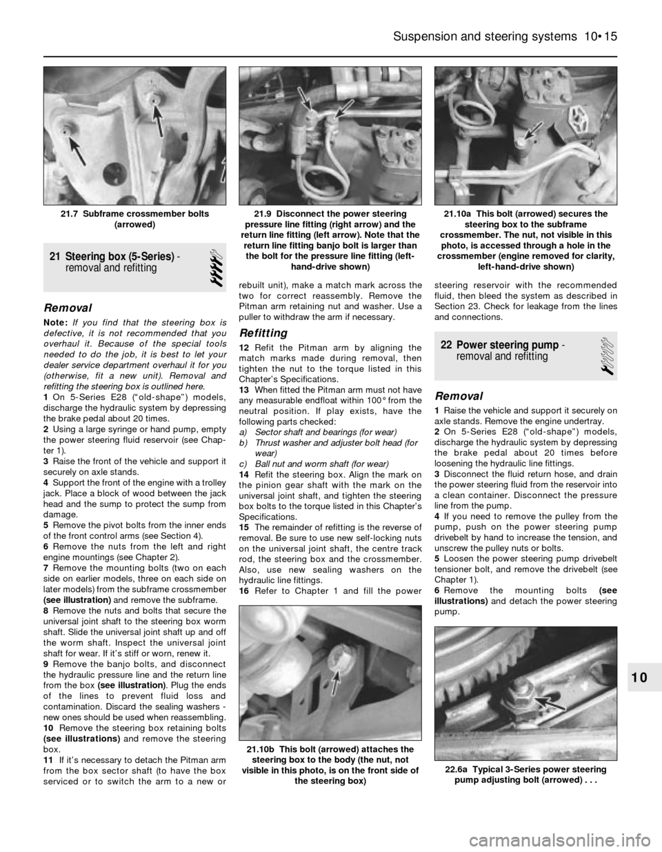
7Remove the mounting bolts (two on each
side on earlier models, three on each side on
later models) from the subframe crossmember
(see illustration)and remove the subframe.
8Remove the nuts and bolts that secure the
universal joint shaft to the steering box worm
shaft. Slide the universal joint shaft up and off
the worm shaft. Inspect the universal joint
shaft for wear. If it’s stiff or worn, renew it.
9Remove the banjo bolts, and disconnect
the hydraulic pressure line and the return line
from the box (see illustration). Plug the ends
of the lines to prevent fluid loss and
contamination. Discard the sealing washers -
new ones should be used when reassembling.
10Remove the steering box retaining bolts
(see illustrations)and remove the steering
box.
11If it’s necessary to detach the Pitman arm
from the box sector shaft (to have the box
serviced or to switch the arm to a new orrebuilt unit), make a match mark across the
two for correct reassembly. Remove the
Pitman arm retaining nut and washer. Use a
puller to withdraw the arm if necessary.
Refitting
12Refit the Pitman arm by aligning the
match marks made during removal, then
tighten the nut to the torque listed in this
Chapter’s Specifications.
13When fitted the Pitman arm must not have
any measurable endfloat within 100° from the
neutral position. If play exists, have the
following parts checked:
a) Sector shaft and bearings (for wear)
b) Thrust washer and adjuster bolt head (for
wear)
c) Ball nut and worm shaft (for wear)
14Refit the steering box. Align the mark on
the pinion gear shaft with the mark on the
universal joint shaft, and tighten the steering
box bolts to the torque listed in this Chapter’s
Specifications.
15The remainder of refitting is the reverse of
removal. Be sure to use new self-locking nuts
on the universal joint shaft, the centre track
rod, the steering box and the crossmember.
Also, use new sealing washers on the
hydraulic line fittings.
16Refer to Chapter 1 and fill the powersteering reservoir with the recommended
fluid, then bleed the system as described in
Section 23. Check for leakage from the lines
and connections.22 Power steering pump-
removal and refitting
1
Removal
1Raise the vehicle and support it securely on
axle stands. Remove the engine undertray.
2On 5-Series E28 (“old-shape”) models,
discharge the hydraulic system by depressing
the brake pedal about 20 times before
loosening the hydraulic line fittings.
3Disconnect the fluid return hose, and drain
the power steering fluid from the reservoir into
a clean container. Disconnect the pressure
line from the pump.
4If you need to remove the pulley from the
pump, push on the power steering pump
drivebelt by hand to increase the tension, and
unscrew the pulley nuts or bolts.
5Loosen the power steering pump drivebelt
tensioner bolt, and remove the drivebelt (see
Chapter 1).
6Remove the mounting bolts (see
illustrations)and detach the power steering
pump.
Suspension and steering systems 10•15
21.10a This bolt (arrowed) secures the
steering box to the subframe
crossmember. The nut, not visible in this
photo, is accessed through a hole in the
crossmember (engine removed for clarity,
left-hand-drive shown)21.9 Disconnect the power steering
pressure line fitting (right arrow) and the
return line fitting (left arrow). Note that the
return line fitting banjo bolt is larger than
the bolt for the pressure line fitting (left-
hand-drive shown)21.7 Subframe crossmember bolts
(arrowed)
22.6a Typical 3-Series power steering
pump adjusting bolt (arrowed) . . .
21.10b This bolt (arrowed) attaches the
steering box to the body (the nut, not
visible in this photo, is on the front side of
the steering box)
10