service indicator BMW 3 SERIES 1983 E30 Workshop Manual
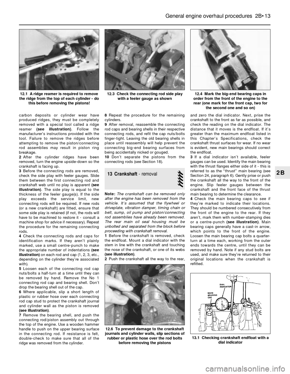
[x] Cancel search | Manufacturer: BMW, Model Year: 1983, Model line: 3 SERIES, Model: BMW 3 SERIES 1983 E30Pages: 228, PDF Size: 7.04 MB
Page 14 of 228
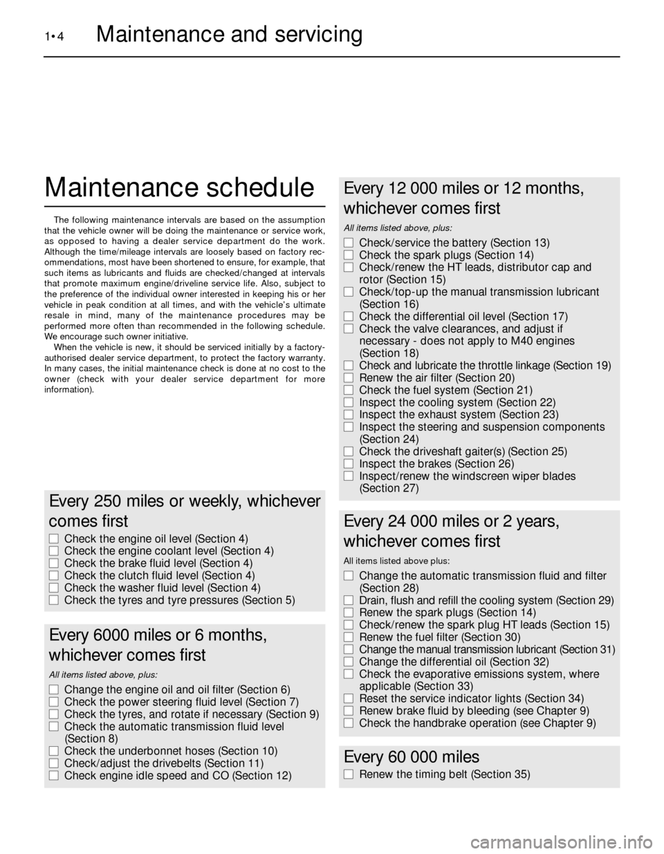
Maintenance schedule
The following maintenance intervals are based on the assumption
that the vehicle owner will be doing the maintenance or service work,
as opposed to having a dealer service department do the work.
Although the time/mileage intervals are loosely based on factory rec-
ommendations, most have been shortened to ensure, for example, that
such items as lubricants and fluids are checked/changed at intervals
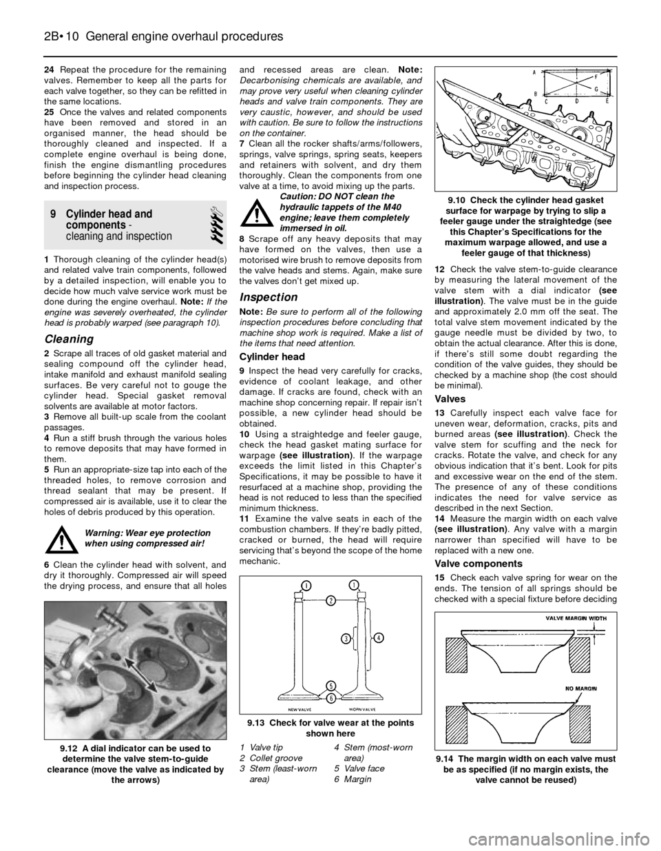
that promote maximum engine/driveline service life. Also, subject to
the preference of the individual owner interested in keeping his or her
vehicle in peak condition at all times, and with the vehicle’s ultimate
resale in mind, many of the maintenance procedures may be
performed more often than recommended in the following schedule.
We encourage such owner initiative.
When the vehicle is new, it should be serviced initially by a factory-
authorised dealer service department, to protect the factory warranty.
In many cases, the initial maintenance check is done at no cost to the
owner (check with your dealer service department for more
information).
1•4Maintenance and servicing
Every 250 miles or weekly, whichever
comes first
m mCheck the engine oil level (Section 4)
m mCheck the engine coolant level (Section 4)
m mCheck the brake fluid level (Section 4)
m mCheck the clutch fluid level (Section 4)
m mCheck the washer fluid level (Section 4)
m mCheck the tyres and tyre pressures (Section 5)
Every 6000 miles or 6 months,
whichever comes first
All items listed above, plus:
m mChange the engine oil and oil filter (Section 6)
m mCheck the power steering fluid level (Section 7)
m mCheck the tyres, and rotate if necessary (Section 9)
m mCheck the automatic transmission fluid level
(Section 8)
m mCheck the underbonnet hoses (Section 10)
m mCheck/adjust the drivebelts (Section 11)
m mCheck engine idle speed and CO (Section 12)
Every 12 000 miles or 12 months,
whichever comes first
All items listed above, plus:
m mCheck/service the battery (Section 13)
m mCheck the spark plugs (Section 14)
m mCheck/renew the HT leads, distributor cap and
rotor (Section 15)
m mCheck/top-up the manual transmission lubricant
(Section 16)
m mCheck the differential oil level (Section 17)
m mCheck the valve clearances, and adjust if
necessary - does not apply to M40 engines
(Section 18)
m mCheck and lubricate the throttle linkage (Section 19)
m mRenew the air filter (Section 20)
m mCheck the fuel system (Section 21)
m mInspect the cooling system (Section 22)
m mInspect the exhaust system (Section 23)
m mInspect the steering and suspension components
(Section 24)
m mCheck the driveshaft gaiter(s) (Section 25)
m mInspect the brakes (Section 26)
m mInspect/renew the windscreen wiper blades
(Section 27)
Every 24 000 miles or 2 years,
whichever comes first
All items listed above plus:
m mChange the automatic transmission fluid and filter
(Section 28)
m mDrain, flush and refill the cooling system (Section 29)
m mRenew the spark plugs (Section 14)
m mCheck/renew the spark plug HT leads (Section 15)
m mRenew the fuel filter (Section 30)
m mChange the manual transmission lubricant (Section 31)
m mChange the differential oil (Section 32)
m mCheck the evaporative emissions system, where
applicable (Section 33)
m mReset the service indicator lights (Section 34)
m mRenew brake fluid by bleeding (see Chapter 9)
m mCheck the handbrake operation (see Chapter 9)
Every 60 000 miles
m
mRenew the timing belt (Section 35)
Page 15 of 228
1•5
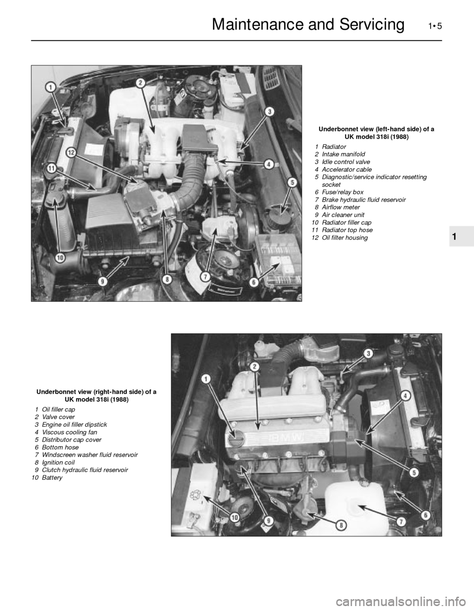
Underbonnet view (left-hand side) of a
UK model 318i (1988)
1 Radiator
2 Intake manifold
3 Idle control valve
4 Accelerator cable
5 Diagnostic/service indicator resetting
socket
6 Fuse/relay box
7 Brake hydraulic fluid reservoir
8 Airflow meter
9 Air cleaner unit
10 Radiator filler cap
11 Radiator top hose
12 Oil filter housing
Underbonnet view (right-hand side) of a
UK model 318i (1988)
1 Oil filler cap
2 Valve cover
3 Engine oil filler dipstick
4 Viscous cooling fan
5 Distributor cap cover
6 Bottom hose
7 Windscreen washer fluid reservoir
8 Ignition coil
9 Clutch hydraulic fluid reservoir
10 Battery
1
Maintenance and Servicing
Page 19 of 228
inhibitors wear out, so it must be renewed at
the specified intervals.
Brake and clutch fluid
Warning: Brake fluid can harm
your eyes and damage painted
surfaces, so use extreme caution
when handling or pouring it. Do
not use brake fluid that has been standing
open or is more than one year old. Brake
fluid absorbs moisture from the air, which
can cause a dangerous loss of brake
effectiveness. Use only the specified type
of brake fluid. Mixing different types (such
as DOT 3 or 4 and DOT 5) can cause brake
failure.
14The brake master cylinder is mounted at
the left rear corner of the engine
compartment. The clutch fluid reservoir
(manual transmission models) is mounted on
the right-hand side.
15To check the clutch fluid level, observe
the level through the translucent reservoir.
The level should be at or near the step
moulded into the reservoir. If the level is low,
remove the reservoir cap to add the specified
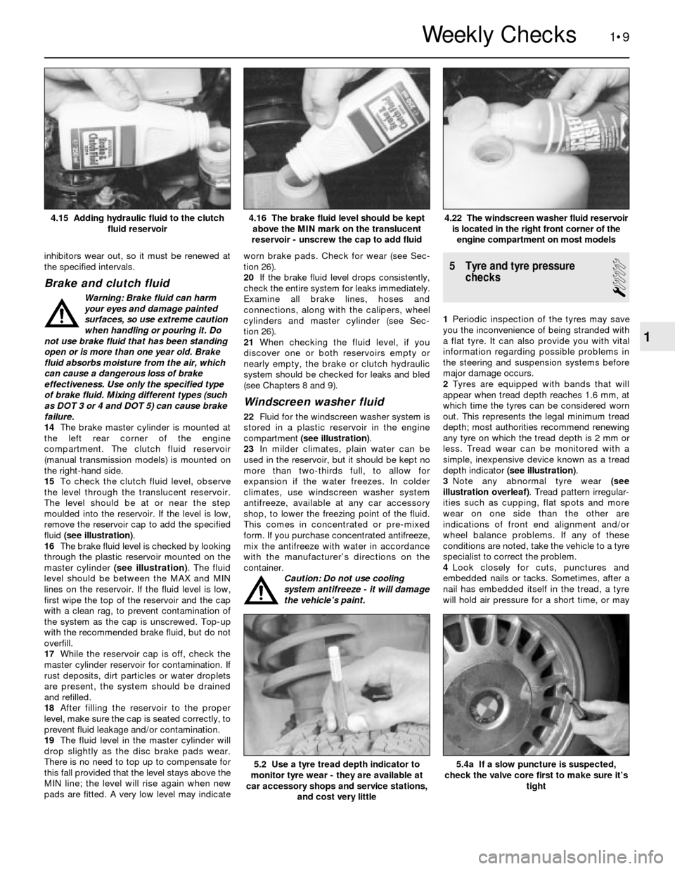
fluid (see illustration).
16The brake fluid level is checked by looking
through the plastic reservoir mounted on the
master cylinder (see illustration). The fluid
level should be between the MAX and MIN
lines on the reservoir. If the fluid level is low,
first wipe the top of the reservoir and the cap
with a clean rag, to prevent contamination of
the system as the cap is unscrewed. Top-up
with the recommended brake fluid, but do not
overfill.
17While the reservoir cap is off, check the
master cylinder reservoir for contamination. If
rust deposits, dirt particles or water droplets
are present, the system should be drained
and refilled.
18After filling the reservoir to the proper
level, make sure the cap is seated correctly, to
prevent fluid leakage and/or contamination.
19The fluid level in the master cylinder will
drop slightly as the disc brake pads wear.
There is no need to top up to compensate for
this fall provided that the level stays above the
MIN line; the level will rise again when new
pads are fitted. A very low level may indicateworn brake pads. Check for wear (see Sec-
tion 26).
20If the brake fluid level drops consistently,
check the entire system for leaks immediately.
Examine all brake lines, hoses and
connections, along with the calipers, wheel
cylinders and master cylinder (see Sec-
tion 26).
21When checking the fluid level, if you
discover one or both reservoirs empty or
nearly empty, the brake or clutch hydraulic
system should be checked for leaks and bled
(see Chapters 8 and 9).
Windscreen washer fluid
22Fluid for the windscreen washer system is
stored in a plastic reservoir in the engine
compartment (see illustration).
23In milder climates, plain water can be
used in the reservoir, but it should be kept no
more than two-thirds full, to allow for
expansion if the water freezes. In colder
climates, use windscreen washer system
antifreeze, available at any car accessory
shop, to lower the freezing point of the fluid.
This comes in concentrated or pre-mixed
form. If you purchase concentrated antifreeze,
mix the antifreeze with water in accordance
with the manufacturer’s directions on the
container.
Caution: Do not use cooling
system antifreeze - it will damage
the vehicle’s paint.
5 Tyre and tyre pressure
checks
1
1Periodic inspection of the tyres may save
you the inconvenience of being stranded with
a flat tyre. It can also provide you with vital
information regarding possible problems in
the steering and suspension systems before
major damage occurs.
2Tyres are equipped with bands that will
appear when tread depth reaches 1.6 mm, at
which time the tyres can be considered worn
out. This represents the legal minimum tread
depth; most authorities recommend renewing
any tyre on which the tread depth is 2 mm or
less. Tread wear can be monitored with a
simple, inexpensive device known as a tread
depth indicator (see illustration).
3Note any abnormal tyre wear (see
illustration overleaf). Tread pattern irregular-
ities such as cupping, flat spots and more
wear on one side than the other are
indications of front end alignment and/or
wheel balance problems. If any of these
conditions are noted, take the vehicle to a tyre
specialist to correct the problem.
4Look closely for cuts, punctures and
embedded nails or tacks. Sometimes, after a
nail has embedded itself in the tread, a tyre
will hold air pressure for a short time, or may
1•9
4.22 The windscreen washer fluid reservoir
is located in the right front corner of the
engine compartment on most models4.16 The brake fluid level should be kept
above the MIN mark on the translucent
reservoir - unscrew the cap to add fluid4.15 Adding hydraulic fluid to the clutch
fluid reservoir
5.4a If a slow puncture is suspected,
check the valve core first to make sure it’s
tight5.2 Use a tyre tread depth indicator to
monitor tyre wear - they are available at
car accessory shops and service stations,
and cost very little
1
Weekly Checks
Page 36 of 228
the lubricant will be hot, it would be wise to
wear rubber gloves.
3Raise the vehicle and place it on axle
stands. Make sure it is safely supported, and
as level as possible.
4Move the necessary equipment under the
vehicle, being careful not to touch any of the
hot exhaust components.
5Place the drain pan under the transmission,
and remove the filler/level plug from the side
of the transmission. Loosen the drain plug
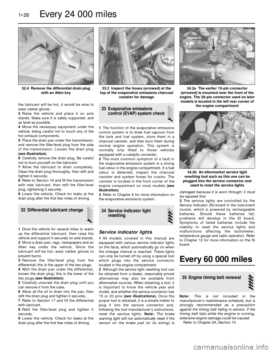
(see illustration).
6Carefully remove the drain plug. Be careful
not to burn yourself on the lubricant.
7Allow the lubricant to drain completely.
Clean the drain plug thoroughly, then refit and
tighten it securely.
8Refer to Section 16 and fill the transmission
with new lubricant, then refit the filler/level
plug, tightening it securely.
9Lower the vehicle. Check for leaks at the
drain plug after the first few miles of driving.
32 Differential lubricant change
1
1Drive the vehicle for several miles to warm
up the differential lubricant, then raise the
vehicle and support it securely on axle stands.
2Move a drain pan, rags, newspapers and an
Allen key under the vehicle. Since the
lubricant will be hot, wear rubber gloves to
prevent burns.
3Remove the filler/level plug from the
differential; this is the upper of the two plugs.
4With the drain pan under the differential,
loosen the drain plug; this is the lower of the
two plugs (see illustration).
5Carefully unscrew the drain plug until you
can remove it from the case.
6Allow all the oil to drain into the pan, then
refit the drain plug and tighten it securely.
7Refer to Section 17 and fill the differential
with lubricant.
8Refit the filler/level plug and tighten it
securely.
9Lower the vehicle. Check for leaks at the
drain plug after the first few miles of driving.
33 Evaporative emissions
control (EVAP) system check
1
1The function of the evaporative emissions
control system is to draw fuel vapours from
the tank and fuel system, store them in a
charcoal canister, and then burn them during
normal engine operation. This system is
normally only fitted to those vehicles
equipped with a catalytic converter.
2The most common symptom of a fault in
the evaporative emissions system is a strong
fuel odour in the engine compartment. If a fuel
odour is detected, inspect the charcoal
canister and system hoses for cracks. The
canister is located in the front corner of the
engine compartment on most models (see
illustration).
3Refer to Chapter 6 for more information on
the evaporative emissions system.
34 Service indicator light
resetting
4
Service indicator lights
1All models covered in this manual are
equipped with various service indicator lights
on the facia, which automatically go on when
the mileage interval is reached. These lights
can only be turned off by using a special tool
which plugs into the service connector
located in the engine compartment.
2Although the service light resetting tool can
be obtained from a dealer, reasonably-priced
alternatives may also be available from
aftermarket sources. When obtaining a tool, it
is important to know the vehicle year and
model, and whether the service connector has
15 or 20 pins (see illustrations). Once the
proper tool is obtained, it is a simple matter to
plug it into the service connector and,
following the tool manufacturer’s instructions,
reset the service lights. Note: The brake
warning light will not automatically reset if the
sensor on the brake pad (or its wiring) isdamaged because it is worn through: it must
be repaired first.
3The service lights are controlled by the
Service Indicator (SI) board in the instrument
cluster, which is powered by rechargeable
batteries. Should these batteries fail,
problems will develop in the SI board.
Symptoms of failed batteries include the
inability to reset the service lights and
malfunctions affecting the tachometer,
temperature gauge and radio operation. Refer
to Chapter 12 for more information on the SI
board.
Every 60 000 miles
35 Engine timing belt renewal
5
Note:This is not included in the
manufacturer’s maintenance schedule, but is
strongly recommended as a precaution
against the timing belt failing in service. If the
timing belt fails while the engine is running,
extensive engine damage could be caused.
Refer to Chapter 2A, Section 10.
1•26
34.2b An aftermarket service light
resetting tool such as this one can be
plugged into the service connector and
used to reset the service lights
34.2a The earlier 15-pin connector
(arrowed) is mounted near the front of the
engine. The 20-pin connector used on later
models is located in the left rear corner of
the engine compartment33.2 Inspect the hoses (arrowed) at the
top of the evaporative emissions charcoal
canister for damage32.4 Remove the differential drain plug
with an Allen key
Every 24 000 miles
Page 66 of 228
24Repeat the procedure for the remaining
valves. Remember to keep all the parts for
each valve together, so they can be refitted in
the same locations.
25Once the valves and related components
have been removed and stored in an
organised manner, the head should be
thoroughly cleaned and inspected. If a
complete engine overhaul is being done,
finish the engine dismantling procedures
before beginning the cylinder head cleaning
and inspection process.
9 Cylinder head and
components-
cleaning and inspection
4
1Thorough cleaning of the cylinder head(s)
and related valve train components, followed
by a detailed inspection, will enable you to
decide how much valve service work must be
done during the engine overhaul. Note: If the
engine was severely overheated, the cylinder
head is probably warped (see paragraph 10).
Cleaning
2Scrape all traces of old gasket material and
sealing compound off the cylinder head,
intake manifold and exhaust manifold sealing
surfaces. Be very careful not to gouge the
cylinder head. Special gasket removal
solvents are available at motor factors.
3Remove all built-up scale from the coolant
passages.
4Run a stiff brush through the various holes
to remove deposits that may have formed in
them.
5Run an appropriate-size tap into each of the
threaded holes, to remove corrosion and
thread sealant that may be present. If
compressed air is available, use it to clear the
holes of debris produced by this operation.
Warning: Wear eye protection
when using compressed air!
6Clean the cylinder head with solvent, and
dry it thoroughly. Compressed air will speed
the drying process, and ensure that all holesand recessed areas are clean. Note:
Decarbonising chemicals are available, and
may prove very useful when cleaning cylinder
heads and valve train components. They are
very caustic, however, and should be used
with caution. Be sure to follow the instructions
on the container.
7Clean all the rocker shafts/arms/followers,
springs, valve springs, spring seats, keepers
and retainers with solvent, and dry them
thoroughly. Clean the components from one
valve at a time, to avoid mixing up the parts.
Caution: DO NOT clean the
hydraulic tappets of the M40
engine; leave them completely
immersed in oil.
8Scrape off any heavy deposits that may
have formed on the valves, then use a
motorised wire brush to remove deposits from
the valve heads and stems. Again, make sure
the valves don’t get mixed up.
Inspection
Note: Be sure to perform all of the following
inspection procedures before concluding that
machine shop work is required. Make a list of
the items that need attention.
Cylinder head
9Inspect the head very carefully for cracks,
evidence of coolant leakage, and other
damage. If cracks are found, check with an
machine shop concerning repair. If repair isn’t
possible, a new cylinder head should be
obtained.
10Using a straightedge and feeler gauge,
check the head gasket mating surface for
warpage (see illustration). If the warpage
exceeds the limit listed in this Chapter’s
Specifications, it may be possible to have it
resurfaced at a machine shop, providing the
head is not reduced to less than the specified
minimum thickness.
11Examine the valve seats in each of the
combustion chambers. If they’re badly pitted,
cracked or burned, the head will require
servicing that’s beyond the scope of the home
mechanic.12Check the valve stem-to-guide clearance
by measuring the lateral movement of the
valve stem with a dial indicator (see
illustration). The valve must be in the guide
and approximately 2.0 mm off the seat. The
total valve stem movement indicated by the
gauge needle must be divided by two, to
obtain the actual clearance. After this is done,
if there’s still some doubt regarding the
condition of the valve guides, they should be
checked by a machine shop (the cost should
be minimal).
Valves
13Carefully inspect each valve face for
uneven wear, deformation, cracks, pits and
burned areas (see illustration). Check the
valve stem for scuffing and the neck for
cracks. Rotate the valve, and check for any
obvious indication that it’s bent. Look for pits
and excessive wear on the end of the stem.
The presence of any of these conditions
indicates the need for valve service as
described in the next Section.
14Measure the margin width on each valve
(see illustration). Any valve with a margin
narrower than specified will have to be
replaced with a new one.
Valve components
15Check each valve spring for wear on the
ends. The tension of all springs should be
checked with a special fixture before deciding
2B•10 General engine overhaul procedures
9.14 The margin width on each valve must
be as specified (if no margin exists, the
valve cannot be reused)
9.13 Check for valve wear at the points
shown here
9.12 A dial indicator can be used to
determine the valve stem-to-guide
clearance (move the valve as indicated by
the arrows)
9.10 Check the cylinder head gasket
surface for warpage by trying to slip a
feeler gauge under the straightedge (see
this Chapter’s Specifications for the
maximum warpage allowed, and use a
feeler gauge of that thickness)
1 Valve tip
2 Collet groove
3 Stem (least-worn
area)4 Stem (most-worn
area)
5 Valve face
6 Margin
Page 69 of 228
carbon deposits or cylinder wear have
produced ridges, they must be completely
removed with a special tool called a ridge
reamer (see illustration). Follow the
manufacturer’s instructions provided with the
tool. Failure to remove the ridges before
attempting to remove the piston/connecting
rod assemblies may result in piston ring
breakage.
2After the cylinder ridges have been
removed, turn the engine upside-down so the
crankshaft is facing up.
3Before the connecting rods are removed,
check the side play with feeler gauges. Slide
them between the first connecting rod and
crankshaft web until no play is apparent (see
illustration). The side play is equal to the
thickness of the feeler gauge(s). If the side
play exceeds the service limit, new
connecting rods will be required. If new rods
(or a new crankshaft) are fitted, ensure that
some side play is retained (if not, the rods will
have to be machined to restore it - consult a
machine shop for advice if necessary). Repeat
the procedure for the remaining connecting
rods.
4Check the connecting rods and caps for
identification marks. If they aren’t plainly
marked, use a small centre-punch to make
the appropriate number of indentations (see
illustration)on each rod and cap (1, 2, 3, etc.,
depending on the cylinder they’re associated
with).
5Loosen each of the connecting rod cap
nuts/bolts a half-turn at a time until they can
be removed by hand. Remove the No 1
connecting rod cap and bearing shell. Don’t
drop the bearing shell out of the cap.
6Where applicable, slip a short length of
plastic or rubber hose over each connecting
rod cap stud to protect the crankshaft journal
and cylinder wall as the piston is removed
(see illustration).
7Remove the bearing shell, and push the
connecting rod/piston assembly out through
the top of the engine. Use a wooden hammer
handle to push on the upper bearing surface
in the connecting rod. If resistance is felt,
double-check to make sure that all of the
ridge was removed from the cylinder.8Repeat the procedure for the remaining
cylinders.
9After removal, reassemble the connecting
rod caps and bearing shells in their respective
connecting rods, and refit the cap nuts/bolts
finger-tight. Leaving the old bearing shells in
place until reassembly will help prevent the
connecting big-end bearing surfaces from
being accidentally nicked or gouged.
10Don’t separate the pistons from the
connecting rods (see Section 18).
13 Crankshaft- removal
5
Note: The crankshaft can be removed only
after the engine has been removed from the
vehicle. It’s assumed that the flywheel or
driveplate, vibration damper, timing chain or
belt, sump, oil pump and piston/connecting
rod assemblies have already been removed.
The rear main oil seal housing must be
unbolted and separated from the block before
proceeding with crankshaft removal.
1Before the crankshaft is removed, check
the endfloat. Mount a dial indicator with the
stem in line with the crankshaft and touching
the nose of the crankshaft, or one of its webs
(see illustration).
2Push the crankshaft all the way to the rear,and zero the dial indicator. Next, prise the
crankshaft to the front as far as possible, and
check the reading on the dial indicator. The
distance that it moves is the endfloat. If it’s
greater than the maximum endfloat listed in
this Chapter’s Specifications, check the
crankshaft thrust surfaces for wear. If no wear
is evident, new main bearings should correct
the endfloat.
3If a dial indicator isn’t available, feeler
gauges can be used. Identify the main bearing
with the thrust flanges either side of it - this is
referred to as the “thrust” main bearing (see
Section 24, paragraph 6). Gently prise or push
the crankshaft all the way to the front of the
engine. Slip feeler gauges between the
crankshaft and the front face of the thrust
main bearing to determine the clearance.
4Check the main bearing caps to see if
they’re marked to indicate their locations.
They should be numbered consecutively from
the front of the engine to the rear. If they
aren’t, mark them with number-stamping dies
or a centre-punch (see illustration). Main
bearing caps generally have a cast-in arrow,
which points to the front of the engine.
Loosen the main bearing cap bolts a quarter-
turn at a time each, working from the outer
ends towards the centre, until they can be
removed by hand. Note if any stud bolts are
used, and make sure they’re returned to their
original locations when the crankshaft is
refitted.
General engine overhaul procedures 2B•13
12.4 Mark the big-end bearing caps in
order from the front of the engine to the
rear (one mark for the front cap, two for
the second one and so on)12.3 Check the connecting rod side play
with a feeler gauge as shown12.1 A ridge reamer is required to remove
the ridge from the top of each cylinder - do
this before removing the pistons!
13.1 Checking crankshaft endfloat with a
dial indicator
12.6 To prevent damage to the crankshaft
journals and cylinder walls, slip sections of
rubber or plastic hose over the rod bolts
before removing the pistons
2B
Page 169 of 228
12
Chapter 12 Body electrical systems
Bulb renewal . . . . . . . . . . . . . . . . . . . . . . . . . . . . . . . . . . . . . . . . . . . 15
Central locking system - description and check . . . . . . . . . . . . . . . . 20
Cruise control system - description and check . . . . . . . . . . . . . . . . 19
Direction indicator/hazard warning flasher - check and renewal . . . 5
Electric windows - description and check . . . . . . . . . . . . . . . . . . . . 21
Electrical system fault finding - general information . . . . . . . . . . . . . 2
Fuses - general information . . . . . . . . . . . . . . . . . . . . . . . . . . . . . . . 3
General information . . . . . . . . . . . . . . . . . . . . . . . . . . . . . . . . . . . . . . 1
Headlight housing - removal and refitting . . . . . . . . . . . . . . . . . . . . . 14
Headlights - adjustment . . . . . . . . . . . . . . . . . . . . . . . . . . . . . . . . . . 13
Headlights - bulb renewal . . . . . . . . . . . . . . . . . . . . . . . . . . . . . . . . . 12Heated rear window - check and repair . . . . . . . . . . . . . . . . . . . . . . 17
Ignition switch - removal and refitting . . . . . . . . . . . . . . . . . . . . . . . . 7
Instrument cluster - removal and refitting . . . . . . . . . . . . . . . . . . . . . 10
Radio - removal and refitting . . . . . . . . . . . . . . . . . . . . . . . . . . . . . . . 8
Radio aerial - removal and refitting . . . . . . . . . . . . . . . . . . . . . . . . . . 9
Relays - general information . . . . . . . . . . . . . . . . . . . . . . . . . . . . . . . 4
Service Indicator (SI) board - general information . . . . . . . . . . . . . . 11
Steering column switches - removal and refitting . . . . . . . . . . . . . . . 6
Supplemental Restraint System (SRS) - general information . . . . . . 18
Windscreen/tailgate wiper motor - removal and refitting . . . . . . . . . 16
Wiring diagrams - general information . . . . . . . . . . . . . . . . . . . . . . . 22
12•1
Easy,suitable for
novice with little
experienceFairly easy,suitable
for beginner with
some experienceFairly difficult,
suitable for competent
DIY mechanic
Difficult,suitable for
experienced DIY
mechanicVery difficult,
suitable for expert
DIY or professional
Degrees of difficulty Contents
1 General information
The chassis electrical system of this vehicle
is of 12-volt, negative earth type. Power for
the lights and all electrical accessories is
supplied by a lead/acid-type battery, which is
charged by the alternator.
This Chapter covers repair and service
procedures for various chassis (non-engine
related) electrical components. For
information regarding the engine electrical
system components (battery, alternator,
distributor and starter motor), see Chapter 5.
Warning: To prevent electrical
short-circuits, fires and injury,
always disconnect the battery
negative terminal before
checking, repairing or renewing electrical
components.
Caution: If the radio in your
vehicle is equipped with an anti-
theft system, make sure you have
the correct activation code
before disconnecting the battery, Refer to
the information on page 0-7 at the front of
this manual before detaching the cable.
Note: If, after connecting the battery, the
wrong language appears on the instrument
panel display, refer to page 0-7 for the
language resetting procedure.
2 Electrical system fault
finding- general information
2
A typical electrical circuit consists of an
electrical component, any switches, relays,
motors, fuses, fusible links or circuit breakers,
etc related to that component, and the wiring
and connectors that link the components to
both the battery and the chassis. To help you
pinpoint an electrical circuit problem, wiring
diagrams are included at the end of this book.
Before tackling any troublesome electrical
circuit, first study the appropriate wiring
diagrams to get a complete understanding of
what makes up that individual circuit.
Troublespots, for instance, can often be
isolated by noting if other components related
to that circuit are routed through the same
fuse and earth connections.
Electrical problems usually stem from
simple causes such as loose or corroded
connectors, a blown fuse, a melted fusible
link, or a bad relay. Inspect all fuses, wires
and connectors in a problem circuit first.
The basic tools needed include a circuit
tester, a high-impedance digital voltmeter, a
continuity tester and a jumper wire with an in-
line circuit breaker for bypassing electrical
components. Before attempting to locate or
define a problem with electrical testinstruments, use the wiring diagrams to
decide where to make the necessary
connections.
Voltage checks
Perform a voltage check first when a circuit
is not functioning properly. Connect one lead
of a circuit tester to either the negative battery
terminal or a known good earth.
Connect the other lead to a connector in
the circuit being tested, preferably nearest to
the battery or fuse. If the bulb of the tester
lights up, voltage is present, which means that
the part of the circuit between the connector
and the battery is problem-free. Continue
checking the rest of the circuit in the same
fashion.
When you reach a point at which no voltage
is present, the problem lies between that point
and the last test point with voltage. Most of
the time, problems can be traced to a loose
connection.Note:Keep in mind that some
circuits receive voltage only when the ignition
key is turned to a certain position.
Electrical fault diagnosis is simple if you
keep in mind that all electrical circuits are
basically electricity running from the battery,
through the wires, switches, relays, fuses and
fusible links to each electrical component
(light bulb, motor, etc) and then to earth, from
where it is passed back to the battery. Any
electrical problem is an interruption in the flow
of electricity to and from the battery.
Page 170 of 228
Finding a short-circuit
One method of finding a short-circuit is to
remove the fuse and connect a test light or
voltmeter in its place. There should be no
voltage present in the circuit. Move the
electrical connectors from side-to-side while
watching the test light. If the bulb goes on,
there is a short to earth somewhere in that
area, probably where the insulation has been
rubbed through. The same test can be
performed on each component in a circuit,
even a switch.
Earth check
Perform a earth check to see whether a
component is properly earthed (passing
current back via the vehicle body). Disconnect
the battery, and connect one lead of a self-
powered test light (often known as a
continuity tester) to a known good earth.
Connect the other lead to the wire or earth
connection being tested. The bulb should
light, indicating a good earth connection. If
not, dismantle the connection, and clean all
relevant parts thoroughly. When re-making
the connection, use serrated (shakeproof)
washers if possible, and tighten all bolts, etc,
securely.
Caution: If the radio in your
vehicle is equipped with an anti-
theft system, make sure you have
the correct activation code
before disconnecting the battery, Refer to
the information on page 0-7 at the front of
this manual before detaching the cable.
Note: If, after connecting the battery, the
wrong language appears on the instrument
panel display, refer to page 0-7 for the
language resetting procedure.
Continuity check
A continuity check determines if there are
any breaks in a circuit - if it is conducting
electricity properly. With the circuit off (no
power in the circuit), a self-powered continuity
tester can be used to check the circuit.
Connect the test leads to both ends of the
circuit, and if the test light comes on, the
circuit is passing current properly. If the light
doesn’t come on, there is a break somewhere
in the circuit. The same procedure can be
used to test a switch, by connecting the
continuity tester to the power-in and power-
out sides of the switch. With the switch turned
on, the test light should come on.
Finding an open-circuit
When diagnosing for possible open-
circuits, it is often difficult to locate them by
sight, because oxidation or terminal
misalignment are hidden by the connectors.
Intermittent problems are often caused by
oxidised or loose connections. Merely
wiggling an electrical connector may correct
the open-circuit condition, albeit temporarily.
Dismantle the connector, and spray with a
water-dispersant aerosol. On simpler
connectors, it may be possible to carefullybend the connector pins inside, to improve
the metal-to-metal contact - don’t damage
the connector in the process, however.
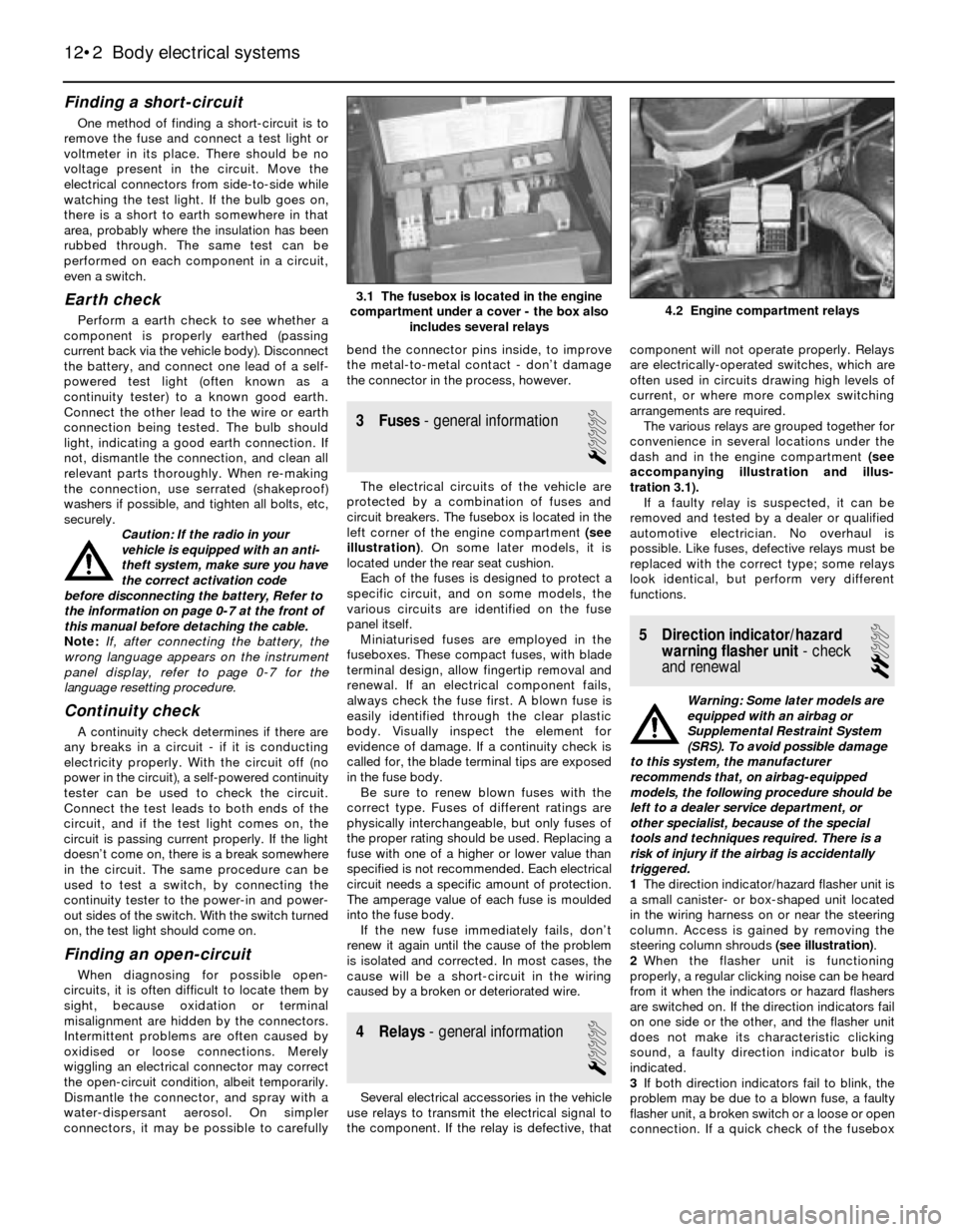
3 Fuses- general information
1
The electrical circuits of the vehicle are
protected by a combination of fuses and
circuit breakers. The fusebox is located in the
left corner of the engine compartment (see
illustration). On some later models, it is
located under the rear seat cushion.
Each of the fuses is designed to protect a
specific circuit, and on some models, the
various circuits are identified on the fuse
panel itself.
Miniaturised fuses are employed in the
fuseboxes. These compact fuses, with blade
terminal design, allow fingertip removal and
renewal. If an electrical component fails,
always check the fuse first. A blown fuse is
easily identified through the clear plastic
body. Visually inspect the element for
evidence of damage. If a continuity check is
called for, the blade terminal tips are exposed
in the fuse body.
Be sure to renew blown fuses with the
correct type. Fuses of different ratings are
physically interchangeable, but only fuses of
the proper rating should be used. Replacing a
fuse with one of a higher or lower value than
specified is not recommended. Each electrical
circuit needs a specific amount of protection.
The amperage value of each fuse is moulded
into the fuse body.
If the new fuse immediately fails, don’t
renew it again until the cause of the problem
is isolated and corrected. In most cases, the
cause will be a short-circuit in the wiring
caused by a broken or deteriorated wire.
4 Relays- general information
1
Several electrical accessories in the vehicle
use relays to transmit the electrical signal to
the component. If the relay is defective, thatcomponent will not operate properly. Relays
are electrically-operated switches, which are
often used in circuits drawing high levels of
current, or where more complex switching
arrangements are required.
The various relays are grouped together for
convenience in several locations under the
dash and in the engine compartment (see
accompanying illustration and illus-
tration 3.1).
If a faulty relay is suspected, it can be
removed and tested by a dealer or qualified
automotive electrician. No overhaul is
possible. Like fuses, defective relays must be
replaced with the correct type; some relays
look identical, but perform very different
functions.
5 Direction indicator/hazard
warning flasher unit- check
and renewal
2
Warning: Some later models are
equipped with an airbag or
Supplemental Restraint System
(SRS). To avoid possible damage
to this system, the manufacturer
recommends that, on airbag-equipped
models, the following procedure should be
left to a dealer service department, or
other specialist, because of the special
tools and techniques required. There is a
risk of injury if the airbag is accidentally
triggered.
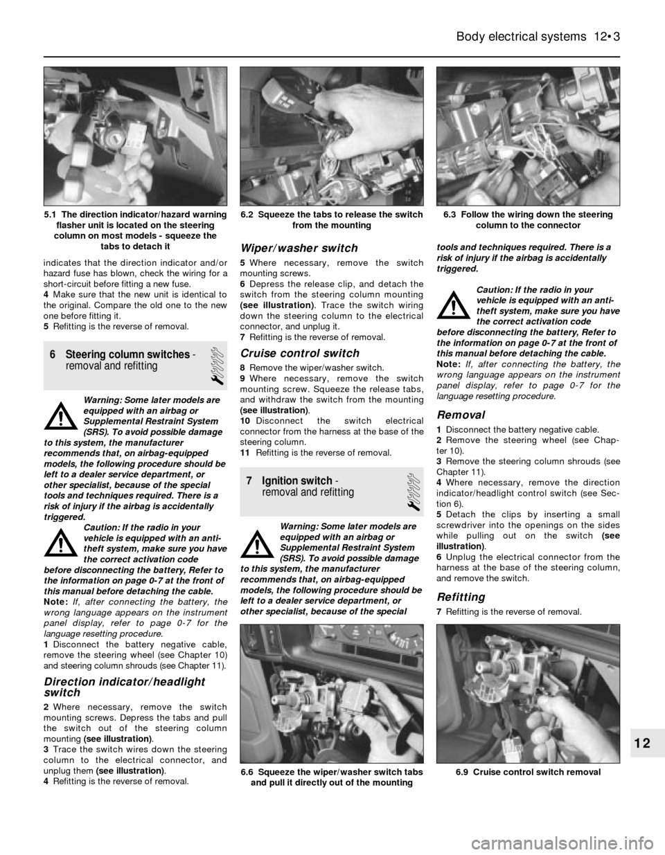
1The direction indicator/hazard flasher unit is
a small canister- or box-shaped unit located
in the wiring harness on or near the steering
column. Access is gained by removing the
steering column shrouds (see illustration).
2When the flasher unit is functioning
properly, a regular clicking noise can be heard
from it when the indicators or hazard flashers
are switched on. If the direction indicators fail
on one side or the other, and the flasher unit
does not make its characteristic clicking
sound, a faulty direction indicator bulb is
indicated.
3If both direction indicators fail to blink, the
problem may be due to a blown fuse, a faulty
flasher unit, a broken switch or a loose or open
connection. If a quick check of the fusebox
12•2 Body electrical systems
4.2 Engine compartment relays3.1 The fusebox is located in the engine
compartment under a cover - the box also
includes several relays
Page 171 of 228
indicates that the direction indicator and/or
hazard fuse has blown, check the wiring for a
short-circuit before fitting a new fuse.
4Make sure that the new unit is identical to
the original. Compare the old one to the new
one before fitting it.
5Refitting is the reverse of removal.
6 Steering column switches-
removal and refitting
1
Warning: Some later models are
equipped with an airbag or
Supplemental Restraint System
(SRS). To avoid possible damage
to this system, the manufacturer
recommends that, on airbag-equipped
models, the following procedure should be
left to a dealer service department, or
other specialist, because of the special
tools and techniques required. There is a
risk of injury if the airbag is accidentally
triggered.
Caution: If the radio in your
vehicle is equipped with an anti-
theft system, make sure you have
the correct activation code
before disconnecting the battery, Refer to
the information on page 0-7 at the front of
this manual before detaching the cable.
Note: If, after connecting the battery, the
wrong language appears on the instrument
panel display, refer to page 0-7 for the
language resetting procedure.
1Disconnect the battery negative cable,
remove the steering wheel (see Chapter 10)
and steering column shrouds (see Chapter 11).
Direction indicator/headlight
switch
2Where necessary, remove the switch
mounting screws. Depress the tabs and pull
the switch out of the steering column
mounting (see illustration).
3Trace the switch wires down the steering
column to the electrical connector, and
unplug them (see illustration).
4Refitting is the reverse of removal.
Wiper/washer switch
5Where necessary, remove the switch
mounting screws.
6Depress the release clip, and detach the
switch from the steering column mounting
(see illustration). Trace the switch wiring
down the steering column to the electrical
connector, and unplug it.
7Refitting is the reverse of removal.
Cruise control switch
8Remove the wiper/washer switch.
9Where necessary, remove the switch
mounting screw. Squeeze the release tabs,
and withdraw the switch from the mounting
(see illustration).
10Disconnect the switch electrical
connector from the harness at the base of the
steering column.
11Refitting is the reverse of removal.
7 Ignition switch-
removal and refitting
1
Warning: Some later models are
equipped with an airbag or
Supplemental Restraint System
(SRS). To avoid possible damage
to this system, the manufacturer
recommends that, on airbag-equipped
models, the following procedure should be
left to a dealer service department, or
other specialist, because of the specialtools and techniques required. There is a
risk of injury if the airbag is accidentally
triggered.
Caution: If the radio in your
vehicle is equipped with an anti-
theft system, make sure you have
the correct activation code
before disconnecting the battery, Refer to
the information on page 0-7 at the front of
this manual before detaching the cable.
Note: If, after connecting the battery, the
wrong language appears on the instrument
panel display, refer to page 0-7 for the
language resetting procedure.
Removal
1Disconnect the battery negative cable.
2Remove the steering wheel (see Chap-
ter 10).
3Remove the steering column shrouds (see
Chapter 11).
4Where necessary, remove the direction
indicator/headlight control switch (see Sec-
tion 6).
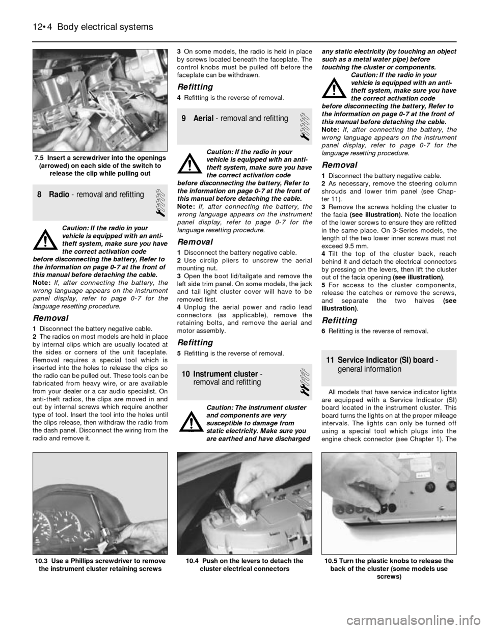
5Detach the clips by inserting a small
screwdriver into the openings on the sides
while pulling out on the switch (see
illustration).
6Unplug the electrical connector from the
harness at the base of the steering column,
and remove the switch.
Refitting
7Refitting is the reverse of removal.
Body electrical systems 12•3
6.3 Follow the wiring down the steering
column to the connector6.2 Squeeze the tabs to release the switch
from the mounting
6.9 Cruise control switch removal6.6 Squeeze the wiper/washer switch tabs
and pull it directly out of the mounting
12
5.1 The direction indicator/hazard warning
flasher unit is located on the steering
column on most models - squeeze the
tabs to detach it
Page 172 of 228
8 Radio- removal and refitting
1
Caution: If the radio in your
vehicle is equipped with an anti-
theft system, make sure you have
the correct activation code
before disconnecting the battery, Refer to
the information on page 0-7 at the front of
this manual before detaching the cable.
Note: If, after connecting the battery, the
wrong language appears on the instrument
panel display, refer to page 0-7 for the
language resetting procedure.
Removal
1Disconnect the battery negative cable.
2The radios on most models are held in place
by internal clips which are usually located at
the sides or corners of the unit faceplate.
Removal requires a special tool which is
inserted into the holes to release the clips so
the radio can be pulled out. These tools can be
fabricated from heavy wire, or are available
from your dealer or a car audio specialist. On
anti-theft radios, the clips are moved in and
out by internal screws which require another
type of tool. Insert the tool into the holes until
the clips release, then withdraw the radio from
the dash panel. Disconnect the wiring from the
radio and remove it.3On some models, the radio is held in place
by screws located beneath the faceplate. The
control knobs must be pulled off before the
faceplate can be withdrawn.
Refitting
4Refitting is the reverse of removal.
9 Aerial- removal and refitting
1
Caution: If the radio in your
vehicle is equipped with an anti-
theft system, make sure you have
the correct activation code
before disconnecting the battery, Refer to
the information on page 0-7 at the front of
this manual before detaching the cable.
Note: If, after connecting the battery, the
wrong language appears on the instrument
panel display, refer to page 0-7 for the
language resetting procedure.
Removal
1Disconnect the battery negative cable.
2Use circlip pliers to unscrew the aerial
mounting nut.
3Open the boot lid/tailgate and remove the
left side trim panel. On some models, the jack
and tail light cluster cover will have to be
removed first.
4Unplug the aerial power and radio lead
connectors (as applicable), remove the
retaining bolts, and remove the aerial and
motor assembly.
Refitting
5Refitting is the reverse of removal.
10 Instrument cluster-
removal and refitting
2
Caution: The instrument cluster
and components are very
susceptible to damage from
static electricity. Make sure you
are earthed and have dischargedany static electricity (by touching an object
such as a metal water pipe) before
touching the cluster or components.
Caution: If the radio in your
vehicle is equipped with an anti-
theft system, make sure you have
the correct activation code
before disconnecting the battery, Refer to
the information on page 0-7 at the front of
this manual before detaching the cable.
Note: If, after connecting the battery, the
wrong language appears on the instrument
panel display, refer to page 0-7 for the
language resetting procedure.
Removal
1Disconnect the battery negative cable.
2As necessary, remove the steering column
shrouds and lower trim panel (see Chap-
ter 11).
3Remove the screws holding the cluster to
the facia (see illustration). Note the location
of the lower screws to ensure they are refitted
in the same place. On 3-Series models, the
length of the two lower inner screws must not
exceed 9.5 mm.
4Tilt the top of the cluster back, reach
behind it and detach the electrical connectors
by pressing on the levers, then lift the cluster
out of the facia opening (see illustration).
5For access to the cluster components,
release the catches or remove the screws,
and separate the two halves (see
illustration).
Refitting
6Refitting is the reverse of removal.
11 Service Indicator (SI) board-
general information
All models that have service indicator lights
are equipped with a Service Indicator (SI)
board located in the instrument cluster. This
board turns the lights on at the proper mileage
intervals. The lights can only be turned off
using a special tool which plugs into the
engine check connector (see Chapter 1). The
12•4 Body electrical systems
10.5 Turn the plastic knobs to release the
back of the cluster (some models use
screws)10.4 Push on the levers to detach the
cluster electrical connectors10.3 Use a Phillips screwdriver to remove
the instrument cluster retaining screws
7.5 Insert a screwdriver into the openings
(arrowed) on each side of the switch to
release the clip while pulling out