Reverse BMW 3 SERIES 1984 E30 Service Manual
[x] Cancel search | Manufacturer: BMW, Model Year: 1984, Model line: 3 SERIES, Model: BMW 3 SERIES 1984 E30Pages: 228, PDF Size: 7.04 MB
Page 121 of 228
Refer to the information on page 0-7 at the
front of this manual before detaching the
cable.
Note: If, after connecting the battery, the
wrong language appears on the instrument
panel display, refer to page 0-7 for the
language resetting procedure.
1Disconnect the battery negative cable.
Bosch alternator
2Remove the voltage regulator from the back
of the alternator (see Section 16).
3Measure the length of the brushes (see
illustration). They should not be less than
6.0 mm. If any are worn past this point, renew
them all as a set. 4Also check for excessively worn slip rings
(see illustration 16.5).
5The brushes are retained either by set
screws or by solder. If you are not skilled at
soldering, it may be best to have an auto
electrician fit the new brushes. Note: Be
careful not to apply heat to the solder joint for
more than 5 seconds. If necessary, use a heat
sink to capture the excess heat. This can be
accomplished by clamping a pair of needle-
nose pliers next to the solder joint.
6On the screw type, hold the assembly in
place and refit the screws. Tighten them
evenly, a little at a time, so the holder isn’t
distorted.
7Refit the regulator assembly to the
alternator.8Reconnect the battery negative cable.
Motorola alternator
9Remove the alternator.
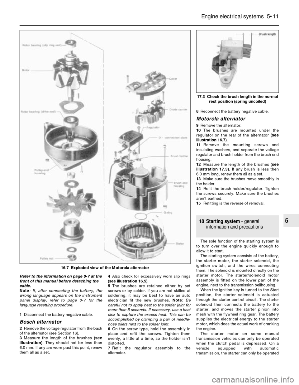
10The brushes are mounted under the
regulator on the rear of the alternator (see
illustration 16.7).
11Remove the mounting screws and
insulating washers, and separate the voltage
regulator and brush holder from the brush end
housing.
12Measure the length of the brushes (see
illustration 17.3). If any brush is less then
6.0 mm long, renew them all as a set.
13Make sure the brushes move smoothly in
the holder.
14Refit the brush holder/regulator. Tighten
the screws securely. Make sure the brushes
aren’t earthed.
15Refitting is the reverse of removal.
18 Starting system- general
information and precautions
The sole function of the starting system is
to turn over the engine quickly enough to
allow it to start.
The starting system consists of the battery,
the starter motor, the starter solenoid, the
ignition switch, and the wires connecting
them. The solenoid is mounted directly on the
starter motor. The starter/solenoid motor
assembly is fitted on the lower part of the
engine, next to the transmission bellhousing.
When the ignition key is turned to the Start
position, the starter solenoid is actuated
through the starter control circuit. The starter
solenoid then connects the battery to the
starter, and moves the starter pinion into
mesh with the flywheel ring gear. The battery
supplies the electrical energy to the starter
motor, which does the actual work of cranking
the engine.
The starter motor on some manual
transmission vehicles can only be operated
when the clutch pedal is depressed. On a
vehicle equipped with automatic
transmission, the starter can only be operated
Engine electrical systems 5•11
17.3 Check the brush length in the normal
rest position (spring uncoiled)
5
16.7 Exploded view of the Motorola alternator
Page 122 of 228
when the transmission selector lever is in Park
or Neutral.
Always detach the battery negative cable
before working on the starting system.
19 Starter motor-
in-vehicle check
2
Note:Before diagnosing starter problems,
make sure the battery is fully charged.
1If the starter motor does not turn at all when
the switch is operated, make sure that the
gear lever is in Neutral or Park (automatic
transmission) or, where applicable, that the
clutch pedal is depressed (manual
transmission).
2Make sure that the battery is charged, and
that all cables, both at the battery and starter
solenoid terminals, are clean and secure.
3If the starter motor spins but the engine is
not cranking, the overrun clutch in the starter
motor is slipping, and the starter motor must
be renewed.
4If, when the switch is actuated, the starter
motor does not operate at all but the solenoid
clicks, then the problem lies either in the
battery, the main solenoid contacts, or the
starter motor itself (or the engine is seized).
5If the solenoid plunger cannot be heard
when the switch is actuated, the battery is
faulty, the switch is defective, the fusible link
is burned-out (the circuit is open), or the
solenoid itself is defective.
6To check the solenoid, connect a jumper
lead between the battery (+) and the ignition
switch wire terminal (the small terminal) on the
solenoid. If the starter motor now operates,
the solenoid is OK and the problem is in the
ignition switch, starter inhibitor switch
(automatic transmission models), clutch
switch (some manual transmission models), or
the wiring.
7If the starter motor still does not operate,
remove the starter/solenoid assembly for
dismantling, testing and repair.
8If the starter motor cranks the engine at an
abnormally-slow speed, first make sure that
the battery is charged, and that all terminal
connections are tight. If the engine is partially-
seized, or has the wrong viscosity oil in it, it
will crank slowly.
9Run the engine until normal operating
temperature is reached, then disconnect the
coil HT lead from the distributor cap and earth
it on the engine.
10Connect a voltmeter positive lead to the
battery positive post, and connect the
negative lead to the negative post.11Crank the engine, and take the voltmeter
readings as soon as a steady figure is
indicated. Do not allow the starter motor to
turn for more than 10 seconds at a time. A
reading of 9 volts or more, with the starter
motor turning at normal cranking speed, is
normal. If the reading is 9 volts or more but
the cranking speed is slow, the solenoid
contacts are burned, there is a bad
connection, or the starter motor itself is faulty.
If the reading is less than 9 volts and the
cranking speed is slow, the starter motor is
faulty or the battery is responsible (defective
or discharged).
20 Starter motor-
removal and refitting
1
Note:If the starter motor is defective, it should
be renewed, or taken to an auto electrical
specialist for repair. Overhaul of the starter
motor is unlikely to be a practical proposition
for the home mechanic, even if spare parts are
available. However, the solenoid can be
renewed separately (see Section 21).
Removal
Caution: If the radio in your
vehicle is equipped with an anti-
theft system, make sure you
have the correct activation code
before disconnecting the battery. Refer to
the information on page 0-7 at the front of
this manual before detaching the cable.
Note: If, after connecting the battery, the
wrong language appears on the instrument
panel display, refer to page 0-7 for the
language resetting procedure.
1Detach the battery negative cable.
2Raise the vehicle and support it securely on
axle stands.
3Clearly label the wires from the terminals onthe starter motor and solenoid, then
disconnect them. Note: On some models, it
may be necessary to remove the air cleaner
(see Chapter 4), coolant expansion tank (see
Chapter 3) and the heater hoses to gain
access to the top of the starter. Carefully label
any hoses or components that need to be
removed from the engine compartment, to
avoid confusion when reassembling.
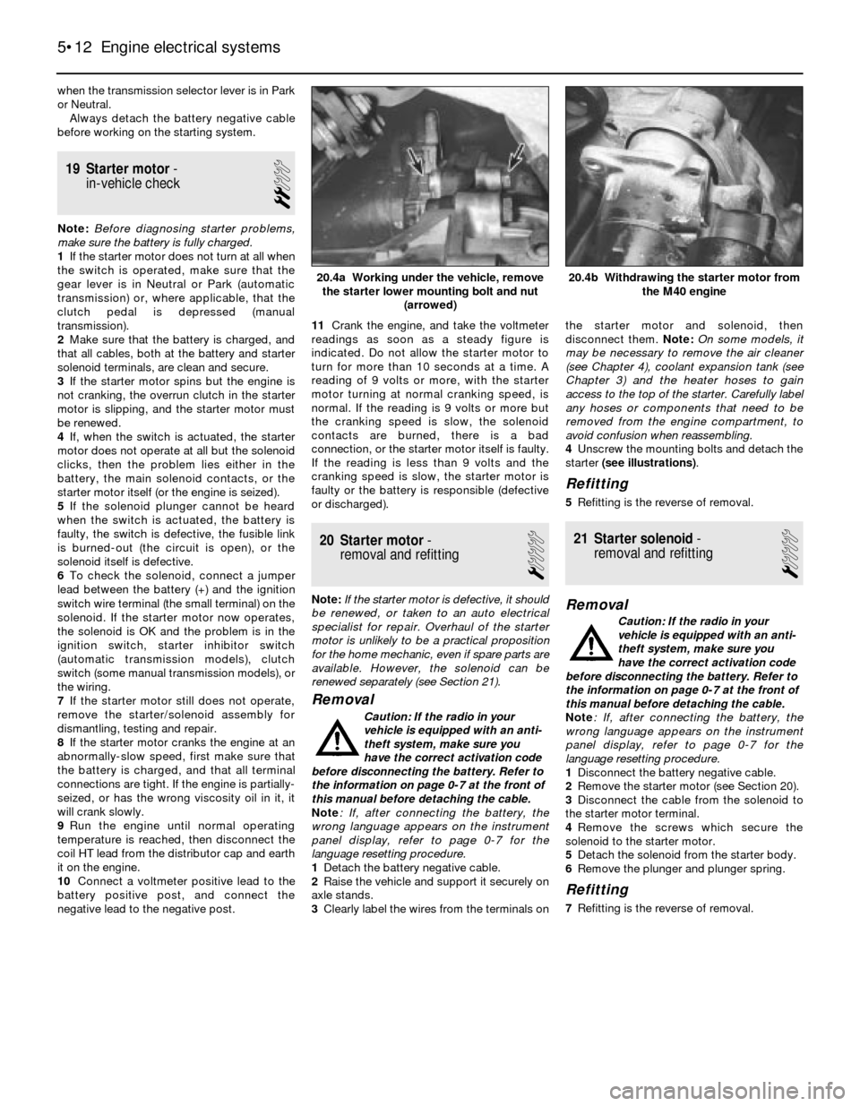
4Unscrew the mounting bolts and detach the
starter (see illustrations).
Refitting
5Refitting is the reverse of removal.
21 Starter solenoid-
removal and refitting
1
Removal
Caution: If the radio in your
vehicle is equipped with an anti-
theft system, make sure you
have the correct activation code
before disconnecting the battery. Refer to
the information on page 0-7 at the front of
this manual before detaching the cable.
Note: If, after connecting the battery, the
wrong language appears on the instrument
panel display, refer to page 0-7 for the
language resetting procedure.
1Disconnect the battery negative cable.
2Remove the starter motor (see Section 20).
3Disconnect the cable from the solenoid to
the starter motor terminal.
4Remove the screws which secure the
solenoid to the starter motor.
5Detach the solenoid from the starter body.
6Remove the plunger and plunger spring.
Refitting
7Refitting is the reverse of removal.
5•12 Engine electrical systems
20.4b Withdrawing the starter motor from
the M40 engine20.4a Working under the vehicle, remove
the starter lower mounting bolt and nut
(arrowed)
Page 124 of 228
4 Information sensors
2
Note:Refer to Chapters 4 and 5 for additional
information on the location and diagnosis of
the information sensors that are not covered in
this Section.
Coolant temperature sensor
General description
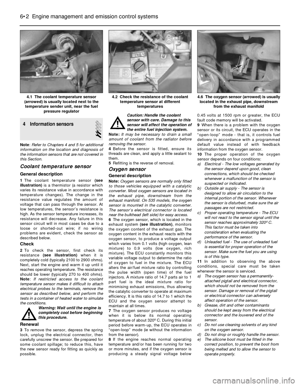
1The coolant temperature sensor (see
illustration)is a thermistor (a resistor which
varies its resistance value in accordance with
temperature changes). The change in the
resistance value regulates the amount of
voltage that can pass through the sensor. At
low temperatures, the sensor’s resistance is
high. As the sensor temperature increases, its
resistance will decrease. Any failure in this
sensor circuit will in most cases be due to a
loose or shorted-out wire; if no wiring
problems are evident, check the sensor as
described below.
Check
2To check the sensor, first check its
resistance (see illustration)when it is
completely cold (typically 2100 to 2900 ohms).
Next, start the engine and warm it up until it
reaches operating temperature. The resistance
should be lower (typically 270 to 400 ohms).
Note: If restricted access to the coolant
temperature sensor makes it difficult to attach
electrical probes to the terminals, remove the
sensor as described below, and perform the
tests in a container of heated water to simulate
the conditions.
Warning: Wait until the engine is
completely cool before beginning
this procedure.
Renewal
3To remove the sensor, depress the spring
lock, unplug the electrical connector, then
carefully unscrew the sensor. Be prepared for
some coolant spillage; to reduce this, have
the new sensor ready for fitting as quickly as
possible.Caution: Handle the coolant
sensor with care. Damage to this
sensor will affect the operation of
the entire fuel injection system.
Note: It may be necessary to drain a small
amount of coolant from the radiator before
removing the sensor.
4Before the sensor is fitted, ensure its
threads are clean, and apply a little sealant to
them.
5Refitting is the reverse of removal.
Oxygen sensor
General description
Note:Oxygen sensors are normally only fitted
to those vehicles equipped with a catalytic
converter. Most oxygen sensors are located in
the exhaust pipe, downstream from the
exhaust manifold. On 535 models, the oxygen
sensor is mounted in the catalytic converter.
The sensor’s electrical connector is located
near the bulkhead (left side) for easy access.
6The oxygen sensor, which is located in the
exhaust system (see illustration), monitors
the oxygen content of the exhaust gas. The
oxygen content in the exhaust reacts with the
oxygen sensor, to produce a voltage output
which varies from 0.1 volts (high oxygen, lean
mixture) to 0.9 volts (low oxygen, rich
mixture). The ECU constantly monitors this
variable voltage output to determine the ratio
of oxygen to fuel in the mixture. The ECU
alters the air/fuel mixture ratio by controlling
the pulse width (open time) of the fuel
injectors. A mixture ratio of 14.7 parts air to 1
part fuel is the ideal mixture ratio for
minimising exhaust emissions, thus allowing
the catalytic converter to operate at maximum
efficiency. It is this ratio of 14.7 to 1 which the
ECU and the oxygen sensor attempt to
maintain at all times.
7The oxygen sensor produces no voltage
when it is below its normal operating
temperature of about 320º C. During this initial
period before warm-up, the ECU operates in
“open-loop” mode (ie without the information
from the sensor).
8If the engine reaches normal operating
temperature and/or has been running for two
or more minutes, and if the oxygen sensor is
producing a steady signal voltage below 0.45 volts at 1500 rpm or greater, the ECU
fault code memory will be activated.
9When there is a problem with the oxygen
sensor or its circuit, the ECU operates in the
“open-loop” mode - that is, it controls fuel
delivery in accordance with a programmed
default value instead of with feedback
information from the oxygen sensor.
10The proper operation of the oxygen
sensor depends on four conditions:
a) Electrical - The low voltages generated by
the sensor depend upon good, clean
connections, which should be checked
whenever a malfunction of the sensor is
suspected or indicated.
b) Outside air supply - The sensor is
designed to allow air circulation to the
internal portion of the sensor. Whenever
the sensor is disturbed, make sure the air
passages are not restricted.
c) Proper operating temperature - The ECU
will not react to the sensor signal until the
sensor reaches approximately 320º C.
This factor must be taken into
consideration when evaluating the
performance of the sensor.
d) Unleaded fuel - The use of unleaded fuel
is essential for proper operation of the
sensor. Make sure the fuel you are using
is of this type.
11In addition to observing the above
conditions, special care must be taken
whenever the sensor is serviced.
a) The oxygen sensor has a permanently-
attached pigtail and electrical connector,
which should not be removed from the
sensor. Damage or removal of the pigtail
or electrical connector can adversely
affect operation of the sensor.
b) Grease, dirt and other contaminants
should be kept away from the electrical
connector and the louvered end of the
sensor.
c) Do not use cleaning solvents of any kind
on the oxygen sensor.
d) Do not drop or roughly handle the sensor.
e) The silicone boot must be fitted in the
correct position, to prevent the boot from
being melted and to allow the sensor to
operate properly.
6•2 Engine management and emission control systems
4.6 The oxygen sensor (arrowed) is usually
located in the exhaust pipe, downstream
from the exhaust manifold4.2 Check the resistance of the coolant
temperature sensor at different
temperatures4.1 The coolant temperature sensor
(arrowed) is usually located next to the
temperature sender unit, near the fuel
pressure regulator
Page 131 of 228
and cause the system to malfunction. If
the ABS wiring harness is damaged in any
way, it must be renewed.
Caution: Make sure the ignition is
turned off before unplugging or
re-making any electrical
connections.
Diagnosis and repair
If the dashboard warning light comes on
and stays on while the vehicle is in operation,
the ABS system requires attention. Although
special electronic ABS diagnostic testing
tools are necessary to properly diagnose the
system, you can perform a few preliminary
checks before taking the vehicle to a dealer
service department.
a) Check the brake fluid level in the
reservoir.
b) Verify that the electronic control unit
connectors are securely connected.
c) Check the electrical connectors at the
hydraulic control unit.
d) Check the fuses.
e) Follow the wiring harness to each front
and rear wheel, and verify that all
connections are secure and that the
wiring is undamaged.
If the above preliminary checks do not
rectify the problem, the vehicle should bediagnosed by a dealer service department.
Due to the complex nature of this system, all
actual repair work must be done by a dealer
service department.
3 Disc brake pads- renewal
2
Warning: Disc brake pads must
be renewed on both front wheels
or both rear wheels at the same
time - NEVER renew the pads on
only one wheel. Also, the dust created by
the brake system may contain asbestos,
which is harmful to your health. Never
blow it out with compressed air, and don’t
inhale any of it. An approved filtering mask
should be worn when working on the
brakes. Do not, under any circumstances,
use petroleum-based solvents to clean
brake parts. Use brake system cleaner
only! When servicing the disc brakes, use
only original-equipment or high-quality
brand-name pads.
Warning: Brake fluid is
poisonous. It is also an effective
paint stripper. Refer to the
warning at the start of Section 16.
Note:This procedure applies to both the front
and rear disc brakes.
1Remove the cap(s) from the brake fluid
reservoir, and syphon off about two-thirds of
the fluid from the reservoir. Failing to do thiscould result in the reservoir overflowing when
the caliper pistons are pressed back into their
bores.
2Loosen the wheel bolts, raise the front or
rear of the vehicle and support it securely on
axle stands.
3Remove the front or rear wheels, as
applicable. Work on one brake assembly at a
time, using the assembled brake for reference
if necessary.
4Inspect the brake disc carefully as outlined
in Section 5. If machining is necessary, follow
the information in that Section to remove the
disc, at which time the pads can be removed
from the calipers as well.
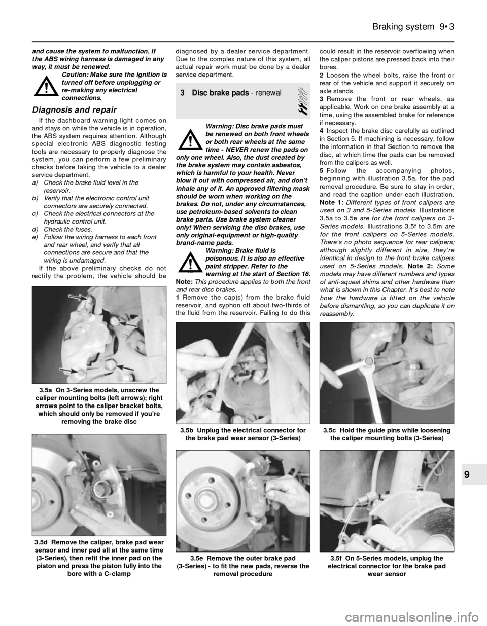
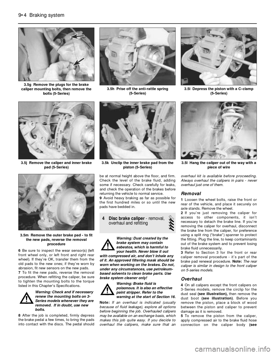
5Follow the accompanying photos,
beginning with illustration 3.5a, for the pad
removal procedure. Be sure to stay in order,
and read the caption under each illustration.
Note 1:Different types of front calipers are
used on 3 and 5-Series models. Illustrations
3.5a to 3.5e are for the front calipers on 3-
Series models.Illustrations 3.5f to 3.5m are
for the front calipers on 5-Series models.
There’s no photo sequence for rear calipers;
although slightly different in size, they’re
identical in design to the front brake calipers
used on 5-Series models.Note 2: Some
models may have different numbers and types
of anti-squeal shims and other hardware than
what is shown in this Chapter. It’s best to note
how the hardware is fitted on the vehicle
before dismantling, so you can duplicate it on
reassembly.
Braking system 9•3
3.5c Hold the guide pins while loosening
the caliper mounting bolts (3-Series)3.5b Unplug the electrical connector for
the brake pad wear sensor (3-Series)
3.5a On 3-Series models, unscrew the
caliper mounting bolts (left arrows); right
arrows point to the caliper bracket bolts,
which should only be removed if you’re
removing the brake disc
3.5f On 5-Series models, unplug the
electrical connector for the brake pad
wear sensor3.5e Remove the outer brake pad
(3-Series) - to fit the new pads, reverse the
removal procedure
3.5d Remove the caliper, brake pad wear
sensor and inner pad all at the same time
(3-Series), then refit the inner pad on the
piston and press the piston fully into the
bore with a C-clamp
9
Page 132 of 228
6Be sure to inspect the wear sensor(s) (left
front wheel only, or left front and right rear
wheel). If they’re OK, transfer them from the
old pads to the new ones; if they’re worn by
abrasion, fit new sensors on the new pads.
7To fit the new pads, reverse the removal
procedure. When refitting the caliper, be sure
to tighten the mounting bolts to the torque
listed in this Chapter’s Specifications.
Warning: Check and if necessary
renew the mounting bolts on 3-
Series models whenever they are
removed. If in doubt, use new
bolts.
8After the job is completed, firmly depress
the brake pedal a few times, to bring the pads
into contact with the discs. The pedal shouldbe at normal height above the floor, and firm.
Check the level of the brake fluid, adding
some if necessary. Check carefully for leaks,
and check the operation of the brakes before
returning the vehicle to normal service.
9Avoid heavy braking as far as possible for
the first hundred miles or so until the new
pads have bedded in.
4 Disc brake caliper- removal,
overhaul and refitting
4
Warning: Dust created by the
brake system may contain
asbestos, which is harmful to
your health. Never blow it out
with compressed air, and don’t inhale any
of it. An approved filtering mask should be
worn when working on the brakes. Do not,
under any circumstances, use petroleum-
based solvents to clean brake parts. Use
brake system cleaner only!
Warning: Brake fluid is
poisonous. It is also an effective
paint stripper. Refer to the
warning at the start of Section 16.
Note:If an overhaul is indicated (usually
because of fluid leakage), explore all options
before beginning the job. Overhauled calipers
may be available on an exchange basis, which
makes this job quite easy. If you decide to
overhaul the calipers, make sure that anoverhaul kit is available before proceeding.
Always overhaul the calipers in pairs - never
overhaul just one of them.
Removal
1Loosen the wheel bolts, raise the front or
rear of the vehicle, and place it securely on
axle stands. Remove the wheel.
2If you’re just removing the caliper for
access to other components, it isn’t
necessary to detach the brake line. If you’re
removing the caliper for overhaul, disconnect
the brake line from the caliper, for preference
using a split ring (“brake”) spanner to protect
the fitting. Plug the line, to keep contaminants
out of the brake system and to prevent losing
brake fluid unnecessarily.
3Refer to Section 3 for the front or rear
caliper removal procedure - it’s part of the
brake pad renewal procedure. Note:The rear
caliper is similar in design to the front caliper
on 5-series models.
Overhaul
4On all calipers except the front calipers on
3-Series models, remove the circlip for the
dust seal (see illustration),then remove the
dust boot (see illustration). Before you
remove the piston, place a block of wood
between the piston and caliper to prevent
damage as it is removed.
5To remove the piston from the caliper,
apply compressed air to the brake fluid hose
connection on the caliper body (see
9•4 Braking system
3.5l Hang the caliper out of the way with a
piece of wire
3.5m Remove the outer brake pad - to fit
the new pads, reverse the removal
procedure
3.5k Unclip the inner brake pad from the
piston (5-Series)3.5j Remove the caliper and inner brake
pad (5-Series)
3.5i Depress the piston with a C-clamp
(5-Series)3.5h Prise off the anti-rattle spring
(5-Series)3.5g Remove the plugs for the brake
caliper mounting bolts, then remove the
bolts (5-Series)
Page 136 of 228
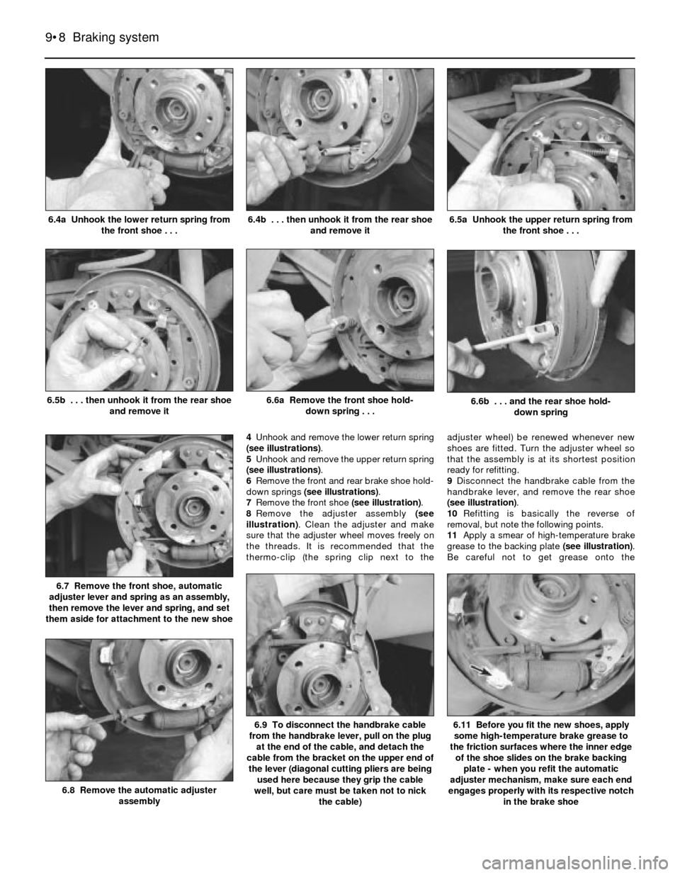
4Unhook and remove the lower return spring
(see illustrations).
5Unhook and remove the upper return spring
(see illustrations).
6Remove the front and rear brake shoe hold-
down springs (see illustrations).
7Remove the front shoe (see illustration).
8Remove the adjuster assembly (see
illustration). Clean the adjuster and make
sure that the adjuster wheel moves freely on
the threads. It is recommended that the
thermo-clip (the spring clip next to theadjuster wheel) be renewed whenever new
shoes are fitted. Turn the adjuster wheel so
that the assembly is at its shortest position
ready for refitting.
9Disconnect the handbrake cable from the
handbrake lever, and remove the rear shoe
(see illustration).
10Refitting is basically the reverse of
removal, but note the following points.
11Apply a smear of high-temperature brake
grease to the backing plate (see illustration).
Be careful not to get grease onto the
9•8 Braking system
6.11 Before you fit the new shoes, apply
some high-temperature brake grease to
the friction surfaces where the inner edge
of the shoe slides on the brake backing
plate - when you refit the automatic
adjuster mechanism, make sure each end
engages properly with its respective notch
in the brake shoe6.9 To disconnect the handbrake cable
from the handbrake lever, pull on the plug
at the end of the cable, and detach the
cable from the bracket on the upper end of
the lever (diagonal cutting pliers are being
used here because they grip the cable
well, but care must be taken not to nick
the cable)
6.8 Remove the automatic adjuster
assembly
6.7 Remove the front shoe, automatic
adjuster lever and spring as an assembly,
then remove the lever and spring, and set
them aside for attachment to the new shoe
6.6b . . . and the rear shoe hold-
down spring6.6a Remove the front shoe hold-
down spring . . .6.5b . . . then unhook it from the rear shoe
and remove it
6.5a Unhook the upper return spring from
the front shoe . . .6.4b . . . then unhook it from the rear shoe
and remove it6.4a Unhook the lower return spring from
the front shoe . . .
Page 138 of 228
expel the air from the master cylinder. A large
Phillips screwdriver can be used to push on
the piston assembly.
11To prevent air from being drawn back into
the master cylinder, the plug must be refitted
and tightened down before releasing the
pressure on the piston assembly.
12Repeat the procedure until brake fluid free
of air bubbles is expelled from the brake line
outlet hole. Repeat the procedure with the
other outlet hole and plug. Be sure to keep the
master cylinder reservoir filled with brake
fluid, to prevent the introduction of air into the
system.
13High pressure is not involved in the bench
bleeding procedure, so the plugs described
above need not be refitted each time the
piston is released, if wished. Instead, before
releasing the piston, simply put your finger
tightly over the hole to keep air from being
drawn back into the master cylinder. Wait
several seconds for brake fluid to be drawn
from the reservoir into the piston bore, then
depress the piston again, removing your
finger as brake fluid is expelled. Be sure to put
your finger back over the hole each time
before releasing the piston, and when the
bleeding procedure is complete for that outlet,
refit the plug and tighten it up before going on
to the other port.
Refitting
14Refit the master cylinder (together with a
new O-ring) over the studs on the brake servo,
and tighten the mounting nuts only finger-tight
at this time.
15Thread the brake line fittings into the
master cylinder. Since the master cylinder is
still a bit loose, it can be moved slightly in
order for the fittings to thread in easily. Do not
strip the threads as the fittings are tightened.
16Tighten the brake fittings securely, and
the mounting nuts to the torque listed in this
Chapter’s Specifications.
17Fill the master cylinder reservoir with fluid,
then bleed the master cylinder (only if the
cylinder has not already been bled) and the
brake system as described in Section 16.
18To bleed the cylinder on the vehicle, have
an assistant pump the brake pedal severaltimes and then hold the pedal to the floor.
Loosen the fitting nut to allow air and fluid to
escape, then tighten the nut. Repeat this
procedure on both fittings until the fluid is
clear of air bubbles. Test the operation of the
brake system carefully before returning the
vehicle to normal service.
8 Brake vacuum servo-
check, removal and refitting
3
Operating check
1Depress the brake pedal several times with
the engine off, until there is no change in the
pedal travel.
2Depress and hold the pedal, then start the
engine. If the pedal goes down slightly,
operation is normal.
Airtightness check
3Start the engine, and turn it off after one or
two minutes. Depress the brake pedal several
times slowly. If the pedal goes down further
the first time but gradually rises after the
second or third depression, the servo is
airtight.
4Depress the brake pedal while the engine is
running, then stop the engine with the pedal
depressed. If there is no change in the pedal
travel after holding the pedal for 30 seconds,
the servo is airtight.
Removal and refitting
5Dismantling the vacuum servo requires
special tools, and cannot be performed by the
home mechanic. If a problem develops, it is
recommended that a new unit be fitted.
6Remove the master cylinder as described in
Section 7.
7Disconnect the vacuum hose from the
brake servo.
8Working in the passenger compartment,
remove the glovebox and lower left-hand trim
panels.
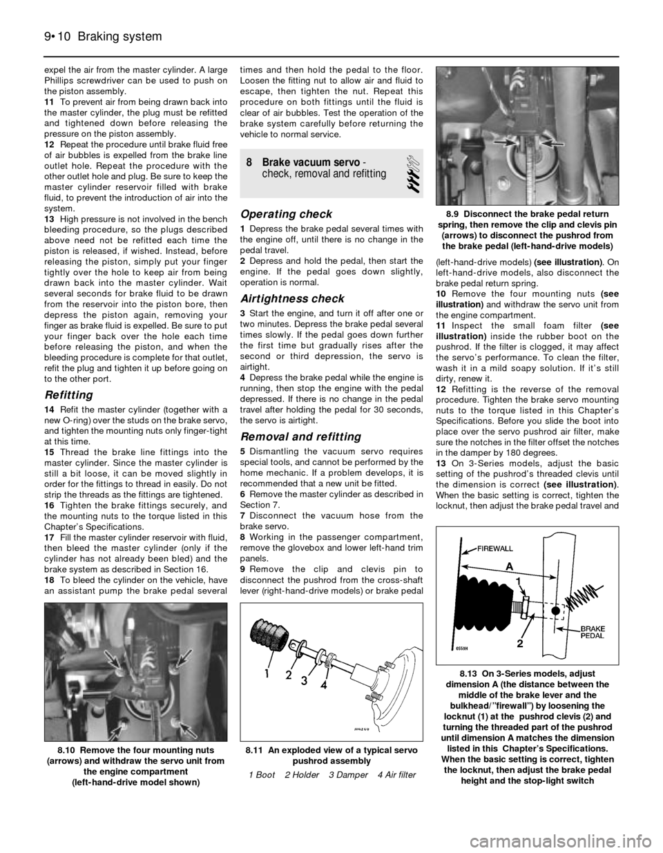
9Remove the clip and clevis pin to
disconnect the pushrod from the cross-shaft
lever (right-hand-drive models) or brake pedal(left-hand-drive models) (see illustration). On
left-hand-drive models, also disconnect the
brake pedal return spring.
10Remove the four mounting nuts (see
illustration)and withdraw the servo unit from
the engine compartment.
11Inspect the small foam filter (see
illustration)inside the rubber boot on the
pushrod. If the filter is clogged, it may affect
the servo’s performance. To clean the filter,
wash it in a mild soapy solution. If it’s still
dirty, renew it.
12Refitting is the reverse of the removal
procedure. Tighten the brake servo mounting
nuts to the torque listed in this Chapter’s
Specifications. Before you slide the boot into
place over the servo pushrod air filter, make
sure the notches in the filter offset the notches
in the damper by 180 degrees.
13On 3-Series models, adjust the basic
setting of the pushrod’s threaded clevis until
the dimension is correct (see illustration).
When the basic setting is correct, tighten the
locknut, then adjust the brake pedal travel and
9•10 Braking system
8.13 On 3-Series models, adjust
dimension A (the distance between the
middle of the brake lever and the
bulkhead/”firewall”) by loosening the
locknut (1) at the pushrod clevis (2) and
turning the threaded part of the pushrod
until dimension A matches the dimension
listed in this Chapter’s Specifications.
When the basic setting is correct, tighten
the locknut, then adjust the brake pedal
height and the stop-light switch
8.11 An exploded view of a typical servo
pushrod assembly
1 Boot 2 Holder 3 Damper 4 Air filter8.10 Remove the four mounting nuts
(arrows) and withdraw the servo unit from
the engine compartment
(left-hand-drive model shown)
8.9 Disconnect the brake pedal return
spring, then remove the clip and clevis pin
(arrows) to disconnect the pushrod from
the brake pedal (left-hand-drive models)
Page 139 of 228
the stop-light switch (see Section 13). Note:
On right-hand-drive models, the brake pedal
in on the right-hand side of the vehicle, and is
connected to the left-hand side by a cross-
shaft. The adjustment is carried out on the
pushrod at the left-hand side, but the
dimension is measured at the pedal on the
right-hand side.
14On 5-Series models, adjust the brake
pedal height and the stop-light switch (see
Section 13).
15Refit the master cylinder (see Section 7)
and attach the vacuum hose.
16Carefully test the operation of the brakes
before returning the vehicle to normal use
9 Hydraulic brake servo-
description, removal and
refitting
3
Warning: Brake fluid is
poisonous. It is also an effective
paint stripper. Refer to the
warning at the start of Section 16.
Description
1On 5-Series E28 (“old-shape”) models, a
hydraulic brake servo system is fitted. The
servo unit, located between the brake pedal
(left-hand-drive) or cross-shaft lever (right-
hand-drive) and the master cylinder, is
operated by hydraulic pressure generated by
the power steering pump. When the engine is
running, the power steering pump supplies
hydraulic pressure to a power flow regulator/
accumulator. The regulator/accumulator
stores and regulates the pressure to the
hydraulic brake servo. When you press the
brake pedal, the pressure in the servo helps
actuate the master cylinder, reducing pedal
effort.
2The hydraulic brake servo cannot be
overhauled; if it fails, a new one must be fitted.
Testing the system requires special tools, so
even fault diagnosis is beyond the scope of
the home mechanic. If the system fails, take it
to a dealer service department or other
qualified garage for repairs.
Removal and refitting
3With the engine off, discharge the hydraulic
accumulator by depressing the brake pedal
20 times or more.
4Remove the master cylinder (see Section 7).
5Clean the area around the return and
supply line fittings, then disconnect them.
Plug the lines, to prevent dirt from entering the
system, and to prevent further fluid loss.
Caution: Even a particle of dirt
can damage the servo, so be
extremely careful to prevent dirt
from entering the system while
the lines are disconnected.
6Working from inside the passenger
compartment, remove the lower left trim
panels above the brake pedal (left-hand-drive
models) or glovebox and trim (right-hand-drive models). On left-hand-drive models, also
disconnect the pedal return spring.
7Prise off the retaining clip, and disconnect
the pushrod from the brake pedal (see
illustration 8.9) or cross-shaft lever.
8Remove the four mounting nuts and
remove the brake servo (see illus-
tration 8.10).
9Refitting is the reverse of removal. Tighten
the hydraulic lines to the torque listed in this
Chapter’s Specifications. Note:Don’t try to
tighten these fittings without a torque wrench.
If they’re loose, they can leak, which can affect
system operation; if they’re tight, they can be
damaged, and they’ll also leak. You’ll need a
crowfoot-type split ring (“brake”) attachment
for your torque wrench to tighten the fittings
properly.
10When you’re done, bleed the brake
hydraulic system (Section 16) and adjust the
brake pedal travel and the stop-light switch
(see Section 13).
10 Handbrake cable(s)- renewal
2
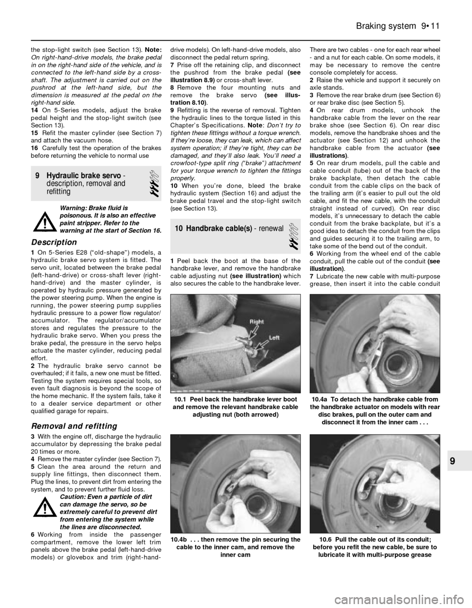
1Peel back the boot at the base of the
handbrake lever, and remove the handbrake
cable adjusting nut (see illustration)which
also secures the cable to the handbrake lever.There are two cables - one for each rear wheel
- and a nut for each cable. On some models, it
may be necessary to remove the centre
console completely for access.
2Raise the vehicle and support it securely on
axle stands.
3Remove the rear brake drum (see Section 6)
or rear brake disc (see Section 5).
4On rear drum models, unhook the
handbrake cable from the lever on the rear
brake shoe (see Section 6). On rear disc
models, remove the handbrake shoes and the
actuator (see Section 12) and unhook the
handbrake cable from the actuator (see
illustrations).
5On rear drum models, pull the cable and
cable conduit (tube) out of the back of the
brake backplate, then detach the cable
conduit from the cable clips on the back of
the trailing arm (it’s easier to pull out the old
cable, and fit the new cable, with the conduit
straight instead of curved). On rear disc
models, it’s unnecessary to detach the cable
conduit from the brake backplate, but it’s a
good idea to detach the conduit from the clips
and guides securing it to the trailing arm, to
take some of the bend out of the conduit.
6Working from the wheel end of the cable
conduit, pull the cable out of the conduit (see
illustration).
7Lubricate the new cable with multi-purpose
grease, then insert it into the cable conduit
Braking system 9•11
10.1 Peel back the handbrake lever boot
and remove the relevant handbrake cable
adjusting nut (both arrowed)
10.6 Pull the cable out of its conduit;
before you refit the new cable, be sure to
lubricate it with multi-purpose grease10.4b . . . then remove the pin securing the
cable to the inner cam, and remove the
inner cam
10.4a To detach the handbrake cable from
the handbrake actuator on models with rear
disc brakes, pull on the outer cam and
disconnect it from the inner cam . . .
9
Page 140 of 228
and push it through until the forward end
comes out at the handbrake lever.
8Insert the cable conduit through the
backplate, and attach the rear end of the
cable to the handbrake lever (rear drum
models) or the actuator (rear disc models).
Make sure you don’t kink the cable while
connecting it.
9Refit the cable conduit to the clips on the
back of the trailing arm.
10On rear drum models, refit the brake
shoes and drum (see Section 6). On rear disc
models, refit the handbrake shoes and
actuator (see Section 12) and the rear brake
disc (see Section 5).
11Lower the vehicle, and refit the adjusting
nut at the handbrake lever. Adjust the
handbrake cable (see Section 11) and refit the
handbrake lever boot.
11 Handbrake- adjustment
2
Rear drum brake models
Note:Adjustment of the handbrake cable(s)
on models with rear drum brakes should only
be necessary when you renew a cable or
detach if from the rear brake assembly for
some reason. Failure of the handbrake system
to hold the vehicle usually indicates worn
brake shoes or a faulty self-adjusting
mechanism.
1Raise the rear of the vehicle, and place it
securely on axle stands.
2Fully release the handbrake lever, then
apply the brakes firmly several times with the
footbrake pedal.
3Pull the handbrake lever up five clicks.
4Tighten or loosen the adjusting nuts by
equal amounts until the rear brake shoes just
begin to drag on the brake drum. You should
feel the same amount of resistance at both
wheels when you rotate them.
5Release the handbrake lever, and verify that
the wheels rotate freely. If they don’t, re-
adjust them.
Rear disc brake models
Note: The handbrake system is not self-
adjusting on models with rear disc brakes. The
handbrake therefore requires periodic
adjustment to compensate for wear. It should
also be adjusted anytime either cable, brake
disc or handbrake assembly is renewed or
removed for some reason.
6Slowly apply the handbrake, and count the
number of clicks at the lever. If the lever can
be pulled up further than the eighth click,
adjust the handbrake cable as follows.
7Peel back the handbrake lever boot, and
loosen the cable adjusting nut (see
illustration 10.1). On some models, it may be
necessary to remove the centre console
completely for access.
8Loosen a single bolt in each rear wheel.Raise the vehicle and place it securely on axle
stands.
9Remove the bolt you loosened in each rear
wheel. Turn the wheel until, using a torch, you
can see the adjuster starwheel through the
bolt hole.
10Turn the adjuster - clockwise to expand
the shoes, anti-clockwise to retract them -
until the brake shoes just contact the brake
drum (see illustration 5.6d). Back off the
brake shoes so the wheel spins freely (three to
four teeth on the adjuster). Note:If the
adjuster starwheel is hard to turn, remove the
wheel and brake disc, lubricate the adjuster
wheel, and try again.
11With the disc fitted, apply the handbrake
three times to stretch and seat the cables,
then slowly pull up on the handbrake lever to
the fifth click. Tighten the cable adjusting nuts
by equal amounts until the rear brake shoes
just touch the brake drum. Verify that both
wheels have the same amount of resistance.
12Release the handbrake, and verify that
both rear wheels rotate freely.
13Tighten the wheel bolts to the torque
listed in Chapter 1 Specifications.
12 Handbrake assembly-
check, removal and refitting
2
Warning: The handbrake linings
on rear disc brake models may
be manufactured of asbestos-
based material. Refer to the
warning at the start of Section 6. When
servicing these components, do not create
dust by grinding or sanding the linings.
1The handbrake system should be checked
regularly. With the vehicle parked on a hill,
apply the handbrake, select neutral, and
check that the handbrake alone will hold the
vehicle when the footbrake is released (be
sure to stay in the vehicle during this check).
However, every 2 years (or whenever a fault is
suspected), the assembly itself should be
inspected.
2With the vehicle raised and supported onaxle stands, remove the rear wheels.
3On rear brake drum models, refer to
Chapter 1; checking the thickness of the
brake shoes is a routine maintenance
procedure.
4On rear disc brake models, remove the rear
discs as outlined in Section 5. Support the
caliper assemblies with a coat hanger or
heavy wire; do not disconnect the brake line
from the caliper.
5With the disc removed, the handbrake
components are visible, and can be inspected
for wear and damage. The linings should last
the life of the vehicle. However, they can wear
down if the handbrake system has been
improperly adjusted, or if the handbrake is
regularly used to stop the vehicle. There is no
minimum thickness specification for the
handbrake shoes, but as a rule of thumb, if
the shoe material is less than 1.5 mm thick,
you should renew them. Also check the
springs and adjuster mechanism and inspect
the drum for deep scratches and other
damage.
Removal and refitting
Note:The following procedure applies only to
models with rear disc brakes. The handbrake
system on models with rear drum brakes is an
integral part of the rear brake assembly (see
Section 6).
6Loosen the rear wheel bolts, raise the rear
of the vehicle and place it securely on axle
stands. Remove the rear wheels. Remove the
brake discs (see Section 5). Work on only one
side at a time, so you can use the other side
as a reference during reassembly, and to
avoid mixing up parts.
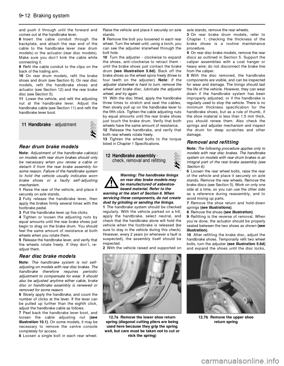
7Remove the shoe return and hold-down
springs (see illustrations).
8Remove the shoes (see illustration).
9Refitting is the reverse of removal. When
you’re done, the actuator should be properly
seated between the two shoes as shown (see
illustration).
10After refitting the brake disc, adjust the
handbrake shoes. Temporarily refit two wheel
bolts, turn the adjuster (see illustration 5.6d)
and expand the shoes until the disc locks,
9•12 Braking system
12.7b Remove the upper shoe
return spring12.7a Remove the lower shoe return
spring (diagonal cutting pliers are being
used here because they grip the spring
well, but care must be taken not to cut or
nick the spring)
Page 142 of 228
simply unscrew it. Plug the open fitting in the
caliper if the hose is removed for any length of
time, to prevent dirt ingress.
5Refitting is the reverse of the removal
procedure. Make sure the brackets are in
good condition and the locknuts are securely
tightened. Renew the spring clips if they don’t
fit tightly.
6Carefully check to make sure the
suspension and steering components do not
make contact with the hoses. Have an
assistant turn the steering wheel from lock-to-
lock during inspection.
7Bleed the brake system as described in
Section 16.
Metal brake line renewal
8When renewing brake lines, use genuine
parts only - preferably from a BMW dealer.
9Genuine BMW brake lines are supplied
straight. You’ll need a pipe-bending tool to
bend them to the proper shape.
10First, remove the line you intend to renew,
lay it on a clean workbench and measure it
carefully. Obtain a new line of the same
length, and bend it to match the pattern of the
old line.
Warning: Do not crimp or
damage the line. No bend should
have a smaller radius than
14 mm. Make sure the protective
coating on the new line is undamaged at
the bends.
11When fitting the new line, make sure it’s
well supported by the brackets, that the
routing matches the original, and that there’s
plenty of clearance between movable
components or those components which will
become hot.
12After refitting, check the master cylinder
fluid level, and add fluid as necessary. Bleed
the brake system as outlined in Section 16,
and test the brakes carefully before driving the
vehicle. Be sure there are no leaks.
16 Brake hydraulic system-
bleeding
3
Warning: Wear eye protection
when bleeding the brake system.
If the fluid comes in contact with
your eyes, immediately rinse
them with water, and seek medical
attention. Most types of brake fluid are
highly flammable, and may ignite if spilled
onto hot engine components, for example.
In this respect, brake fluid should be
treated with as much care as if it were
petrol. When topping-up or renewing the
fluid, always use the recommended type,
and ensure that it comes from a freshly-
opened sealed container. Never re-use old
brake fluid bled from the system, and don’t
top-up with fluid which has been standing
open for a long time, as it is potentially
dangerous to do so.
Note:Bleeding the hydraulic system is
necessary to remove any air which has
entered the system during removal and
refitting of a hose, line, caliper or master
cylinder.
1It will probably be necessary to bleed the
system at all four brakes if air has entered the
system due to low fluid level, or if the brake
lines have been disconnected at the master
cylinder.
2If a brake line was disconnected at only one
wheel, then only that caliper or wheel cylinder
need be bled.
3If a brake line is disconnected at a fitting
located between the master cylinder and any
of the brakes, that part of the system served
by the disconnected line must be bled.
4Bleed the right rear, the left rear, the right
front and the left front brake, in that order,
when the entire system is involved.
5Remove any residual vacuum from the
brake servo by applying the brakes about 30
times with the engine off. This will also relieve
any pressure in the anti-lock brake system
(where applicable).
6Remove the master cylinder reservoir
cover, and fill the reservoir with brake fluid.
Refit the cover. Note:Check the fluid level
often during the bleeding operation, and add
fluid as necessary to prevent the fluid level
from falling low enough to allow air into the
master cylinder.
7Have an assistant on hand, an empty clear
plastic container, and a length of clear plastic
or vinyl tubing to fit over the bleed screws.
Alternatively, a “one-man” bleeding kit can be
used. A “one-man” kit usually contains a tubeor bottle with a one-way valve incorporated -
in this way, the pedal can be pumped as
normal, but air is not drawn back into the
system when the pedal is released. If a one-
man kit is used, follow the instructions
provided with it; similarly with pressure
bleeding kits. In any case, you will also need a
supply of new brake fluid of the
recommended type, and a spanner for the
bleed screw.
8Beginning at the right rear wheel, loosen the
bleed screw slightly, then tighten it to a point
where it is tight but can still be loosened
quickly and easily.
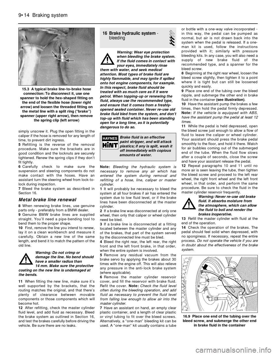
9Place one end of the tubing over the bleed
nipple, and submerge the other end in brake
fluid in the container (see illustration).
10Have the assistant pump the brakes a few
times, then hold the pedal firmly depressed.
Note:If the vehicle is equipped with ABS,
have the assistant pump the pedal at least 12
times.
11While the pedal is held depressed, open
the bleed screw just enough to allow a flow of
fluid to leave the caliper or wheel cylinder.
Your assistant should press the brake pedal
smoothly to the floor, and hold it there. Watch
for air bubbles coming out of the submerged
end of the tube. When the fluid flow slows
after a couple of seconds, close the screw
and have your assistant release the pedal.
12Repeat paragraphs 10 and 11 until no
more air is seen leaving the tube, then tighten
the bleed screw and proceed to the left rear
wheel, the right front wheel and the left front
wheel, in that order, and perform the same
procedure. Be sure to check the fluid in the
master cylinder reservoir frequently.
Warning: Never re-use old brake
fluid. It absorbs moisture from
the atmosphere, which can allow
the fluid to boil and render the
brakes inoperative.
13Refill the master cylinder with fluid at the
end of the operation.
14Check the operation of the brakes. The
pedal should feel solid when depressed, with
no sponginess. If necessary, repeat the entire
process. Do not operate the vehicle if you are
in doubt about the effectiveness of the brake
system.
9•14 Braking system
16.9 Place one end of the tubing over the
bleed screw, and submerge the other end
in brake fluid in the container
15.3 A typical brake line-to-brake hose
connection: To disconnect it, use one
spanner to hold the hex-shaped fitting on
the end of the flexible hose (lower right
arrow) and loosen the threaded fitting on
the metal line with a split ring (“brake”)
spanner (upper right arrow), then remove
the spring clip (left arrow)
Brake fluid is an effective
paint stripper, and will attack
plastics; if any is spilt, wash it
off immediately with copious
amounts of water.